

Abstract
Ion mobility-mass spectrometry (IMS-MS) is used to analyze complex samples and provide structural information of unknown compounds. As the complexity of samples increases, there is a need to improve the resolution of IMS-MS instruments to increase the rate of molecular identification. This work evaluated a cyclable and variable path length (and hence resolving power) multilevel Structures for Lossless Ion Manipulations (SLIM) platform to achieve a higher resolving power than previously possible. This new multilevel SLIM platform has eight separation levels connected by ion escalators, yielding a total path length of ~88 m (~11 m per level). Our new multilevel SLIM can also be operated in an ‘ion cycling’ mode by utilizing a set of return ion escalators that transport ions from the eighth level back to the first, allowing even extendable path lengths (and higher IMS resolution). The platform has been improved to enhance the ion transmission and IMS separation quality by reducing the spacing between SLIM boards. The board thickness was reduced to minimize the ions’ escalator residence time. Compared to the previous generation, the new multilevel SLIM demonstrated a better transmission for a set of phosphazene ions, especially for the low-mobility ions. For example, the transmission of m/z 2834 ions was improved by a factor of ~3 in the new multilevel SLIM. The new multilevel SLIM achieved 49% better resolving powers for GRGDS1+ ions in 4 levels than our previous 4-level SLIM. The collision cross-section-based resolving power of the SLIM platform was tested using a pair of reverse sequence peptides (SDGRG1+, GRGDS1+). We achieved 1100 resolving power using 88 m of path length (i.e., 8 levels) and 1400 following an additional pass through the eight levels. Further evaluation of the multilevel SLIM demonstrated the enhanced separation for a positively and negatively charged brain total lipid extract sample. The new multilevel SLIM enables a tunable high-resolving power for a wide range of ion mobilities and improved transmission for low-mobility ions.
Graphical Abstract
Introduction
Ion mobility spectrometry-mass spectrometry (IMS-MS) is a powerful technique for a variety of applications (e.g., threat detection, food, biomedical research, etc.) due to its ability to provide structural information, improve feature detection, increase throughput, and enhance selectivity.1–6 There is, however, a need to glean more information from increasingly complex samples. One approach to address such need is adding orthogonal separations to IMS-MS such as liquid chromatography, gas chromatography, and electrophoresis.7 Another approach is to increase the resolving power of the IMS to separate more sample constituents. Each of the two approaches has advantages and disadvantages. However, increasing the IMS resolving power is always desired and brings new insights into molecular properties.
In drift tube IMS (DTIMS), a low electric field propels ions through a neutral buffer gas.8 The resolving power can be increased in DTIMS by increasing the voltage applied () which requires an increase in drift tube length to maintain the low electric field. The limitations of the power supplies and the electrical breakdown set the practical limitation of the drift voltage. Additionally, the physical dimensions of the instrument and the available laboratory space can be limiting. Ideally, an increase in the drift tube length without an increase in voltage or the footprint would be advantageous. Traveling wave-based IMS (TWIMS) instruments use relatively low amplitudes electric waveforms to move and separate ions based on their mobilities. Since the waveform can be propagated through the device regardless of its length, TWIMS instruments can provide higher IMS resolving powers than DTIMS. TWIMS instruments include the Waters Synapt, Waters Cyclic, and the Structures for Lossless Ion Manipulations (SLIM).9–11 Although having relatively small footprints, TWIMS-SLIM devices can achieve high-resolution ion mobility separations over long distances (e.g., 13 m).12–17 In TWIMS-SLIM, ions are separated using traveling waves (TWs) that operate at much lower voltages (< 50 V) than required for those used in DTIMS. The separation paths in SLIM are formed between two mirror-image printed circuit boards (PCBs), each having a specific arrangement of different electrodes that function to confine, move, and separate ions. A set of TW electrodes move ions along the separation path and interwoven between them are strip electrodes. RF waveform alternating 180° out-of-phase is applied to adjacent strip electrodes to confine ions between the two surfaces. Running parallel along the exterior of the separation path is a pair of wider strip (guard) electrodes that utilize a DC voltage to confine ions laterally. The separation paths in SLIM adopt a serpentine-like profile to yield the maximum length while confined to the relatively small area of the PCB (e.g., a 13 m path length board is only 45.9 cm × 32.5 cm).13 Since the inception of SLIM, numerous devices and configurations such as SLIM-based ion traps, ion switches, multipass and multilevel operation, the ion escalator, etc. have been explored.12, 13, 15, 17–21 These designs enhanced signal-to-noise ratios and the separation quality of ions without needing to resolve the practical limitations that beleaguered DTIMS. For example, an average resolving power of 1860 was achieved with SLIM when ions of m/z 622 and 922 were cycled around a single serpentine path 40 times (correspond to a path length of ~540 m).12 When operated cyclically, ions are physically constrained to the same path. The distance they travel generally is a multiple of the path length proportional to the number of times the ion is cycled. Although there is no theoretical limit on how many passes a subset of ions can undergo there is a practical limit that depends primarily on the difference of the mobilities of the ions in the subset. After some number of passes, ions with relatively high mobilities will pass those with lower mobilities (i.e., they lap each other). Therefore, ion lapping limits the number of passes ions can be cycled otherwise the arrival time of ions becomes convoluted. There are some informatics efforts to deconvolute the data when ion lapping happens.22 Recently, a strategy was also proposed to extract the collision cross section values from cyclic IMS experiments by taking advantage of the ion velocity, which is constant regardless of the number of cycles.23 However, these efforts require multiple experiments of a variable number of cycles. Other than the ion lapping phenomenon, the width of the ion packet filling the entire path can be limiting. Any further cycling of ions will cause trimming of both ends of the ion packets, distorting the peak shape and loss of ions. Achieving enhanced separations while reducing the prevalence of ion lapping requires longer separation paths.
To achieve greater physical path lengths without increasing the platform’s footprint multiple serpentine paths were stacked to create the first high-resolution variable path length multilevel SLIM.15 In this device, the path length of each level was about 11 m, and a total of four levels was used, providing a total path length of ~43 m. Ions were moved from one level to the next using an ion escalator.15, 18 The multilevel produced an IMS resolving power of 560 for the singly-charged reverse-sequence peptides (SDGRG1+ and GRGDS1+) in helium buffer gas.15
This study presents the initial characterization of the second-generation multilevel SLIM (Gen-2) where the path length has been increased to 88 m. A new return escalator has been added that moves ions from the end of the last level to the start of the separation path on the first level. The performance of the Gen-2 is compared to its predecessor (Gen-1), and the utility of operating it cyclically using the new return escalators is demonstrated.
Experimental Setup
Experiments were performed in either helium (3.0 – 4.0 Torr) or nitrogen (2.3 – 2.6 Torr) buffer gases. The TW and guard conditions were optimized for separation on the first level while the escalator conditions were optimized for transmission. Phosphazene ions (a.k.a. Agilent low concentration tuning mixture ions, AgTM) were purchased from Agilent Technologies, Santa Clara, California, and used unaltered. SDGRG and GRGDS (i.e., reverse peptides) were purchased from Sigma Aldrich (St. Louis, Missouri) and prepared as a 1.0 μM mixture solution in 1:1 acetonitrile:water. Brain total lipids extract (BTLE) was purchased from Avanti Polar Lipids (Alabaster, Alabama) and prepared as 0.5 mg/mL solution in 9:1 methanol:chloroform. All solutions were ionized by electrospray from an etched 20 μm inner diameter capillary emitter by direct infusion at a flow rate of < 400 nL/min using a syringe pump (model Fusion 200, CHEMYX Inc, Stafford, Texas).
The Second-Generation Multilevel SLIM (Gen-2)
The second-generation multilevel SLIM (Gen-2) is an improved version of the original multilevel SLIM (Gen-1) and implements some of the advancements made to the miniSLIM.15, 20 The Gen-2 multilevel SLIM has additional features, such as extending the number of levels from four to eight, which increases the total path length to 88 m. Another feature is a new set of return escalators that allows separating ions at the end of the last level to be sent back to the beginning of the separation path on the first level to enable cyclic operation. Besides the changes made to the SLIM module the remainder of the Gen-2 instrument (i.e., ion source and interface with the MS) is similar to that of the Gen-1.
Figure 1A shows a schematic diagram of the Gen-2 platform. Ions from the ESI source pass through a five-inlet capillary (each was 0.5 mm i.d. and 64 mm long), heated to 170°C, and then through an ion funnel (IF1) of a convoluted ion path held at ~ 9 Torr. Downstream of the IF1, a second vacuum housing holds a slanted ion funnel (IF2), which operates at a gas pressure approximately 100 mTorr lower than the SLIM module to maintain pure buffer gas in the SLIM region. The convoluted path and slanted ion funnels are designed to maximize the transmission of ions from the multi-capillary inlet while minimizing the transmission of droplets and neutrals that usually accompany electrospray plumes and degrade the instrument’s performance over time.
Figure 1:
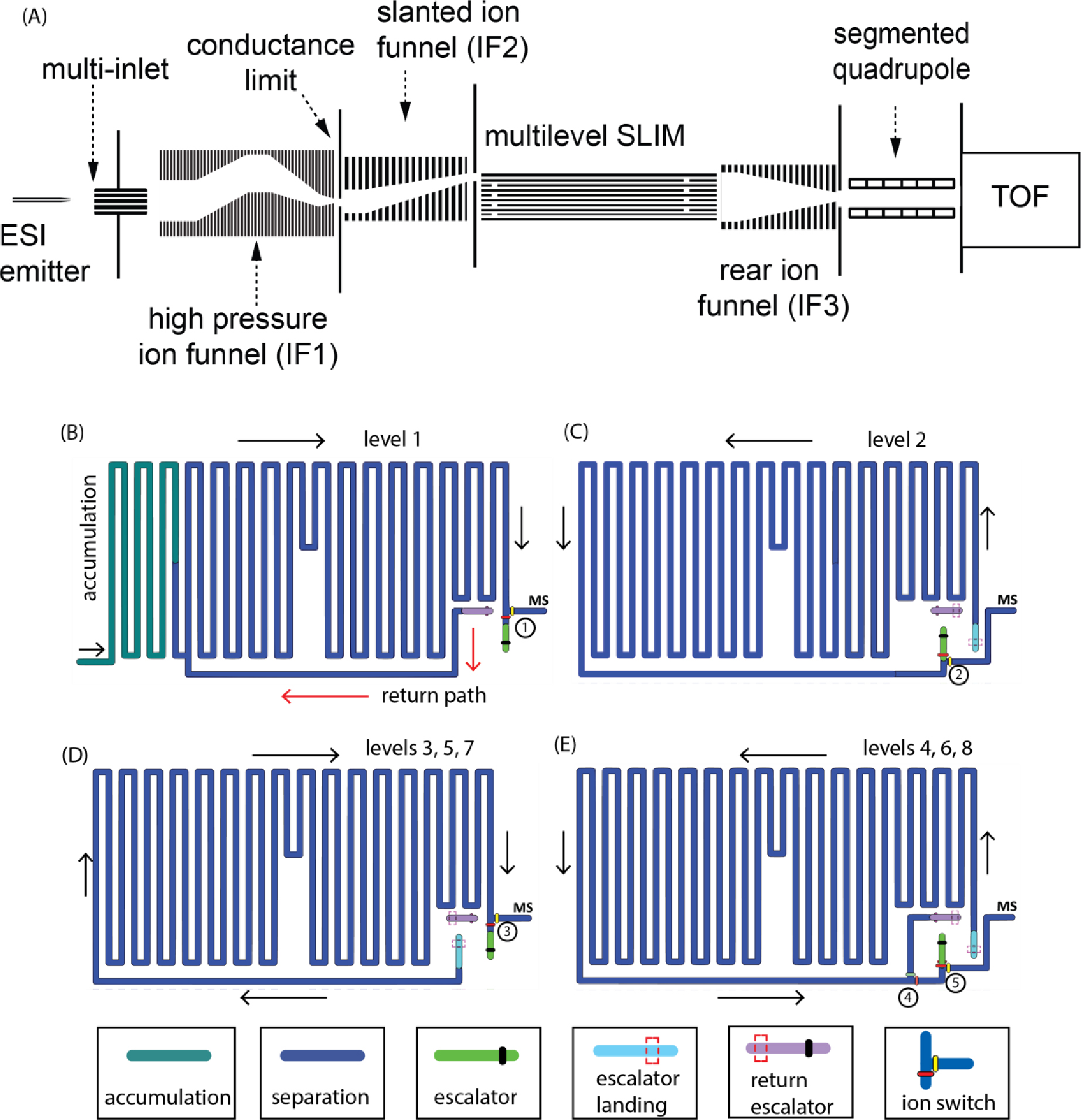
(A) Schematic diagram of the multilevel SLIM. (B) The layout of level 1. (C) The layout of level 2. (D) The layout of levels 3, 5, and 7. (E) The layout of levels 4, 6, and 8.
Ions are then accumulated in a region of the first level (Figure 1B) for a specified time using a low amplitude TW (typically 1 – 3 VPP) at a speed of 192 m/s. After accumulation, ion transmission to the SLIM is blocked by raising the DC voltage applied to the conductance limiting orifice at the end of IF1. Once ion accumulation is complete, the TW amplitude is increased to an optimal value for mobility separation (e.g., 16 – 25 VPP) at a speed of 192 m/s. In the multilevel SLIM, a square TW profile of HHHHLLLL sequence (H refers to the maximum TW while L refers to the minimum TW amplitudes) was utilized.24 When ions reach the end of a level, they can be routed to the next level using the ion escalator or allowed to exit the SLIM where they are collected and focused by a third rear ion funnel (IF3). The lenses in IF3 are rectangular (rather than circular) and progressively decrease across 119 lenses (total length = 129 mm) from 48.4 mm × 17.8 mm at the entrance to 2.8 mm × 2.8 mm at the exit, allowing it to accept ions from any of the eight vertical SLIM levels. Similar to other ion funnels, IF3 is operated with a DC gradient and confining RF superimposed onto each lens, which is made out of printed circuit boards.25 A DC-only circular orifice (2.8 mm i.d.) terminates the ion funnel. Finally, ions exit the IF3 and transmit through the segmented quadrupole26 to the interface of an Agilent 6230B time-of-flight (ToF) mass spectrometer (Agilent Technologies, Santa Clara, California). The signal from the ToF was routed to a SA220P 14-bit 2.0 GHz digitizer (Acqiris, Plan-les-Ouates, Switzerland).27 Data acquisition, voltage settings, and electronics synchronization were performed by in-house developed software.
In this work, we used a multilevel SLIM consisting of 9 printed circuit boards that comprise the eight SLIM levels. Based on our experience with the miniSLIM20, we reduced the PCB thickness from 2.35 mm (Gen-1) to 1.65 mm (Gen-2). We also reduced the separation gap from 3.15 mm (Gen-1) to 2.8 mm (Gen-2) to shorten the residence times of ions through the ion escalators. Each PCB measured 458 mm × 330 mm and when stacked, they had a total height of 36.5 mm. Finally, we were able to control the guard electrodes in the escalator regions independently from the guard electrodes of the separation path, allowing us to optimize ion transmission in the ion escalator region while maintaining optimum separation.
The Gen-2 multilevel SLIM has a new feature that allows it to operate cyclically. This is done by sending a subset of ions near the exit of the last level through a return escalator to the start of the separation path of the first level. The eight levels provided a total cyclable path length of 85.5 m (the return path skips the 2.5 m accumulation region in the first level as shown in Figure 1B. The layouts of the four primary Gen-2 SLIM levels’ are shown in Figures 1B–1E. These four layouts can be used to configure the cyclable path length of the multilevel by alternating the use of the level 3 and 4 layouts. Similar to the Gen-1, the serpentine path of the first level is divided into two sections that can be operated with separate TWs. Prior to SLIM separation, ions are accumulated briefly in a portion of the 2.5-meter region (Figure 1B). Following accumulation the separation begins and ions are moved from the accumulation region into the remainder of the level (8.5 m) by a TW optimized for separation. When ions reach the end of the first level, they encounter an ion switch (consisting of a pair of electrodes – red and yellow ellipses in Figure 1B) which determines the direction of ion motion.12 Ions can exit to the mass spectrometer or continue to the next level through the ion escalator region (colored green) by applying DC or TW voltages to the electrodes controlled by the ion switch. The guard voltage and TW amplitude applied to the ion escalator region are optimized independently of the guard voltage and TW amplitude applied to the separation path to improve transmission through the escalator. A speed of 46 m/s was used for the TW in the escalator region.
After passing through the escalator, ions arrive at the second level (escalator landing, colored light blue in Figure 1C) and separation continues. The ions will continue along the serpentine path of the second level in the direction indicated by the black arrows (Figure 1C) until they reach the second ion switch near the end of level 2. They can be sent to either the third level or the MS (as described earlier). The progression of ions through each remaining level is the same. Ions will continue to separate as they traverse the roughly 11-meter paths of each level (levels 2 – 8) until they reach the ion switches of the last level (switches 4 and 5 in Figure 1E). The ion switches 4 and 5 direct the ions toward the mass spectrometer for detection or to the set of return escalators (purple regions in Figure 1). The ability to exit the ions from any level allows the user to tune the resolving power to the application at hand. Although the 88 m path length provides a very high resolving power, ions can also be cycled through the multilevel SLIM, leading to higher IMS resolving powers. Ions move along the purple regions of each preceding level before arriving at the first level, where they follow the red arrows (Figure 1B) back to the start of separation. The return escalator path length through eight levels and up to the separation path on level one is 0.535 m, contributing minimally to separation. For additional reference, images of the 8-level SLIM module are shown in Supplementary Information Figure S1. A simplified schematic of the ion movement through the return escalator is also shown in Supplementary Information Figure S2. Following an initial separation through all levels, if cyclic operation is desired, the range of ions intended for rerouting is identified. The arrival time window of these ions is used in conjunction with software to control switch 4 on the last level to return the ions to the first level without affecting the separation of the remaining ions, which can move to the mass spectrometer for detection. This capability is crucial in the analyses of complex samples.
Results and Discussion
Ion Transmission.
We first evaluated the transmission of negatively charged AgTM ions in helium gas using each of the eight levels. The peak area of each ion m/z was monitored after each separation level and normalized to the peak area of the same ion following its separation through the first level. In other words, the peak area of each ion measured from the first level was used to define 100% transmission of the ion since it did not pass through any escalator. Through all eight levels, the transmission of ions of 1934 m/z or lower was generally 75% and above (Figure 2) with an average loss of less than 5.5% per level. However, the transmission of ions with m/z > 1934 m/z declined noticeably with each level. Overall, the ion transmission through the first four levels was comparable to the Gen-1, but the transmission of 2834 m/z ions through the fourth level and beyond was better than the Gen-1 by ~ 3 times.
Figure 2:
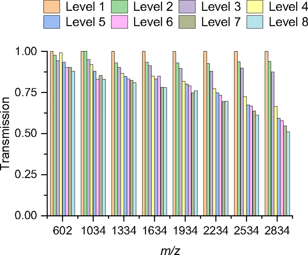
Ion transmission of negatively-charged AgTM through each level. The peak area of each m/z ion was normalized to the peak area of the same ion after it was detected following separation on the first level.
The enhancements made in the Gen-2 likely led to the improved transmission of higher m/z ions through more levels. This was achieved by reducing the PCB thickness and the gap between the surfaces and segmenting the guard voltage in the separation and escalator regions to allow them to be operated independently. By reducing the PCB thickness and gap, the residence time of ions passing through the escalators and their likelihood of rolling over were reduced, improving their transmission.20 Although we did not systematically study the guard effect, we generally observed that the guard in the escalator region required lower voltage than in the separation region.
Resolving power.
The Gen-2’s ability to separate molecules was tested in nitrogen at a pressure of 2.3 Torr using a mixture of two reverse sequence peptides (SDGRG1+ and GRGDS1+) that have the same m/z of 491 but slightly different collision cross sections. The separation of the two peptides was tracked through eight levels and an additional pass (equivalent to 16 levels or 173.5 m). Figure 3 shows the mobiligrams of the two reverse peptides following separation through one, eight, and 16 levels (2 passes). Additional mobiligrams for all levels are included in the Supplementary Information Figure S3. Initially, the peaks from the first level appeared nearly baseline-separated. As the ions moved through each subsequent level, the separation of the two peaks continued to increase, and the resolving powers improved. The CCS-based resolving power was calculated as , where CCS was taken at the peak centroid and ΔCCS was taken at the full width at half maximum (fwhm). The resolution is defined as , where CCS2 and CCS1 are taken at the centroid of each peak and the ΔCCS2 and ΔCCS1 are the fwhm of peak 2 and 1, respectively. The CCS values used for the two reversed peptides in nitrogen were SDGRG1+ = 204 Å2 and GRGDS1+ = 206 Å2.28 In helium the CCS values used were SDGRG1+ = 130 Å2 and GRGDS1+ = 132 Å2.29 The CCS-calibrated mobiligrams are shown in Supplementary Information Figure S4 for 1 level, 4 levels, 8 levels, and a second pass through all eight levels (equivalent to 16 levels). Converting the arrival time to a CCS highlights the increase in resolving power in the multilevel SLIM platform as is evident by the narrowing of peaks. Figure 4A shows a plot of the resolving power as a function of the distance ions traveled and the power function fit of the data. The fitting indicates that the data reasonably follows the square root power function. The resolving powers obtained were similar for both peptides and increased from about 340 (first level) to 1100 after eight levels (i.e., one pass) and over 1400 after the second pass. This is higher than the resolving powers reported using a commercially available cyclic ion mobility platform, which were about 350 and 750 after 15.7 m and 98 m, respectively.11 However, the authors noted that the ion separation was lost beyond 15.7 m (16 passes) due to the ion lapping phenomenon.11 The Gen-2’s ultra-long path is capable of achieving resolving power of 1100 without encountering ion lapping. The Gen-2 resolving power of 1100 is also ~3 times higher than the 13-m single-level SLIM.28 The resolution also increased from 1.9 for level 1 to 6.3 for level 8 and 8.4 for 2 passes (Supplementary Information Figure S5A).
Figure 3:
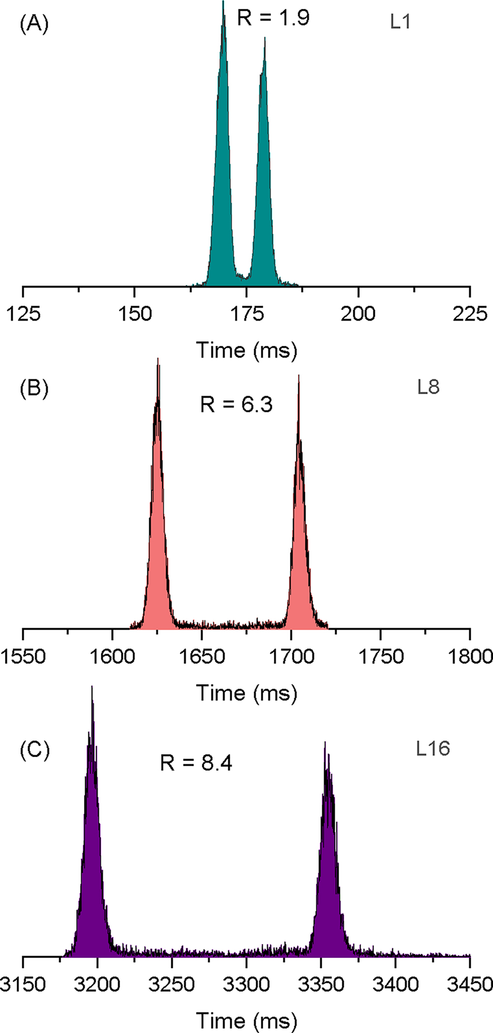
The separation of the SDGRG1+ and GRGDS1+ peptides following separation in nitrogen through (A) the first level (L1), (B) eight levels (L8), and (C) 16 levels (2 passes). The resolution values are also noted.
Figure 4:
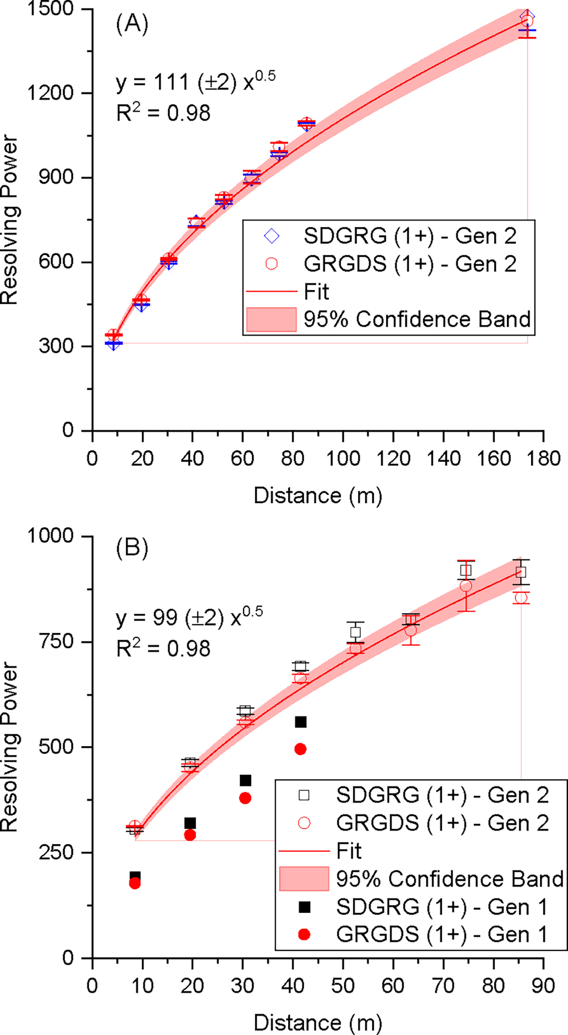
Plots of resolving powers (in terms of CCS) for the SDGRG1+ and GRGDS1+ peptides in (A) nitrogen and (B) helium. Data from the Gen-1 are also shown as solid symbols.
We evaluated the separation performance of the Gen-2 and compared it to the Gen-1. To do this, we measured the CCS-based RPs and temporal resolution of these reverse peptides in helium at 3.4 Torr. We found that the Gen-2 RPs of GRGDS1+ were 342, 466, 612, and 740 after separation on the first, second, third, and fourth levels, respectively (see Figure 4B). These values exceeded the performance of the Gen-1, which had RPs of 178, 292, 380, and 496 for the first, second, third, and fourth levels, respectively (Figure 4B), and represent a 49–92% increase in resolving power.15 The resolving power of the Gen-2 continued to increase as ions traveled through more SLIM levels, reaching an RP ~900 following eight levels. While the nitrogen RPs for both peptides were similar in the Gen-2, in helium, they trended greater for the SDGRG1+ sequence, which was also observed in the Gen-1. The resolution of the first four levels, presented in Supplementary Information Figure S5B, was also improved compared to the Gen-1. Therefore, the improvements made in the Gen-2 in terms of spacing and board thicknesses helped to improve the performance of the ion escalator and, in turn, the resolving power and resolution.
Application to BTLE.
Although the Gen-2 SLIM achieves a resolving power of 1100 we added the option to cycle ions and increase the resolving power of a subset of ions. We further demonstrated the performance of the Gen-2’s ultra-long cyclable path by analyzing a brain total lipid extract (BTLE) in negative and positive ion modes. IMS separations were performed using the first level to establish the range and abundance of ions. A 3D heatmap across the entire m/z range in negative ion mode is shown in Supplementary Information Figure S6A, and a zoomed view of a single peak centered near 200 ms is shown in Supplementary Information Figure S6B. As can be seen, the mobility peak encompasses a mass range centered around an m/z of 840 ±5 that is comprised of multiple unresolved peaks (of different m/z). The extracted mobiligrams in Figure 5 show the evolution of the mobility separation. Initially, there is a single peak exiting level 1 (Figure 5A), but as the separation progresses through the eighth level (Figure 5B), the peak splits into a major peak and three minor peaks labeled 1 – 4. Upon examining the m/z-arrival time heatmap (Supplementary Information Figure S7B), it was observed after separation through the eight levels that the multiple features comprised at least 4 distinct species with overlapped isotopic distributions. Although the four isotopic distributions overlapped in the m/z dimension, they were successfully deconvoluted using the eight levels of multilevel SLIM. While it is possible for informatics tools to deconvolute the overlapped isotopic distributions, the identification can be made more confidently through high-resolution separation in SLIM.
Figure 5:

Mobiligrams of negatively charged BTLE ions for a range of ions (m/z 830–850) acquired after separation through (A) the first level and (B) the eight levels. (C) The 1500 – 1600 ms range of ions in (B) were cycled for three additional passes through the multilevel SLIM.
A range of ions (~1500 – 1600 ms) in Figure 5B was notched from the broad separation and sent back to the start of separation on level one for an additional three passes for a separation equivalent of 32 levels or 344.5 m (Figure 5C). After the third additional pass, the single peak in Figure 5A was evidently formed by at least four features. Comparing Figures 5B and 5C, it is clear that a single pass through the 8 levels was sufficient to separate the features that formed the peak in Figure 5A.
It is important to note that when a specific range of ions is removed from the broad separation and redirected to the start of separation for additional passes, the remaining ions are not affected and are sent to the mass spectrometer for detection. This process can be observed in Supplementary Information Figure S8 as a range of 1500 to 1600 ms absent signal. When the ion switch is activated, ions are diverted to the return escalator and back to the start of the separation path on the first level. During this time, ions do not exit the SLIM, resulting in the absence of signal. The ions preceding and following the notch remain unaffected. In the example shown in Supplementary Information Figure S8, ions before and after the notch were allowed to separate through only eight levels. On the other hand, the notched range continued to separate by cycling through the multilevel SLIM. In this example, the notched ions are detected after they exit the eighth level of the SLIM following their second pass (e.g., ~3000 ms, in Supplementary Information Figure S8). Therefore, there is no loss of information when ions are cycled through the multilevel SLIM.
The second demonstration evaluated the separation performance of the enhanced path length and cyclic capability by using positively charged BTLE ions. Supplementary Information Figure S9A presents a 3D heatmap of the first level separation, which shows a more congested spectrum of ions when compared to the negatively charged BTLE (Supplementary Information Figure S6A). For this demonstration, we limit the discussion to the region shown around an arrival time of 250 ms for which the arrival time is extracted and displayed in Figure 6A. We note a peak in the arrival time dimension (labeled 1 in Figure 6A) with a small shoulder to its right (labeled 2 in Figure 6A) formed by a small population of ions with overlapping isotopic distribution hidden in the m/z dimension. As the separation progressed from the first to the eighth level the overall resolution increased (Supplementary Information Figure S10A) and the two peaks became baseline separated (Figure S10B and Figures 6B). Similar to the previous demonstration, the range of ions encompassing the peaks in Figure 6B were notched from the broad separation and directed through the return escalator for an additional three passes (equivalent to 32 levels or 344.5 m); the resultant arrival time distributions are shown in Figure 6C. We note that the second peak (labeled 2 in Figure 6B) is now well-separated from the base peak and arrives at ~ 6600 ms. The base peak splits into three peaks following the three additional passes (labeled 1a, 1b, and 1c) and they represent different conformers or isomers since they all share the same m/z (Supplementary Information Figure S11). This example demonstrates that while the majority of ions in the mixture can still get a high resolving power using the eight SLIM levels, the cyclic capability of the multilevel is useful for certain cases when more resolving power is needed.
Figure 6:

Mobiligrams of positively charged BTLE ions for a range of ions separated after (A) one level, (B) eight levels, and (C) the range of ions in (B) were cycled for three additional passes.
Conclusions
We introduced the first cyclable variable path length multilevel SLIM to achieve a high IMS resolving power. The new multilevel SLIM is comprised of 8 separation levels to yield an 88 m total path length. The cyclic operation was enabled by using a new set of return escalators that direct the ions from the end of the last level to the start of separation on the first level. We also implemented additional improvements to the multilevel system. We reduced the SLIM PCB thickness from 2.35 mm to 1.65 mm and the spacing between the two surfaces that formed each level from 3.15 mm to 2.8 mm to decrease the residence time of ions passing through the escalators. We also segmented the guards in the escalator and separation regions to allow independent optimization of these regions. We evaluated the ion transmission through each level using negatively charged AgTM ions in helium gas. We compared transmission through the first four levels to the previous four-level SLIM (Gen-1). While we found that the transmission of Gen-2 was comparable to Gen-1, the ions of 2834 m/z were transmitted much better in Gen-2 through all eight levels. The separation performance of the Gen-2 was evaluated using a pair of reverse sequence (SDGRG1+ and GRGDS1+) peptides. We measured a CCS resolving power of approximately 1100 in nitrogen following a single pass separation through the 88 m path. After the ions passed through the return escalator and underwent a second pass, we measured a CCS resolving power of about 1400. We then tested the performance in helium and compared it to the Gen-1. Overall, the CCS resolving powers achieved by the Gen-2 exceeded the Gen-1, regardless of the buffer gas used.
The improved separation and cyclic capability were further demonstrated using negative and positive BTLE ions. A single arrival time distribution of negatively charged ions formed during a first-level separation was then reasonably resolved following its separation through all eight levels, demonstrating the improved separation of the longer multilevel path length. In this experiment, we also demonstrated the advantage of IMS to confidently identify features of overlapped isotopic distributions that are challenging to resolve using a mass spectrometer alone. For the positively charged BTLE ions, a subset of ions was notched from the mixture to demonstrate the cyclic capability, after which new peaks appeared, indicating the cycled peak may contain conformers or isomers that were not observable within the 88 m single-pass separation.
The multilevel SLIM has demonstrated good separation and transmission performance. However, there is still room for improvement, particularly in transmitting high m/z (or low mobility) ions through the ion escalators. The ion escalator has only one electrode lining its interior edge, which can result in longer residence times for low-mobility ions and a greater likelihood of them being lost. Increasing the number of electrodes can reduce ion residence time, but new approaches are required to construct the ion escalator.
This work lays the groundwork for achieving an even higher IMS resolving power. One way to increase the resolution of the multilevel SLIM is to add more levels, but there are practical limits to the number of levels that can be added. As more path length is added, the system’s impedance increases, requiring high power from power supplies to maintain the desired TW and RF parameters. Further innovations and improvements are necessary to routinely achieve IMS resolving powers in the thousands. When these resolving powers are achieved, they will reveal new molecular properties that are currently beyond our reach. Finally, we presented a versatile SLIM platform that can deliver user-tailored IMS resolving powers by leveraging control over the level at which the ions exit. The combined variable path length multilevel and cyclable features are ideal for high throughput applications and more in-depth structural characterizations.
Supplementary Material
Acknowledgments
This work utilized capabilities developed under the support of the NIH National Institute of General Medical Sciences (R01 GM130709-01). This project was performed in the Environmental Molecular Sciences Laboratory, a DOE OBER national scientific user facility on the PNNL campus. PNNL is a multiprogram national laboratory operated by Battelle for the DOE under contract DE-AC05-76RL01830.
Footnotes
The authors declare no competing financial interest.
Associated Content
Supporting Information
Photographs of the 8-level SLIM; simplified representation of the return escalator path in a SLIM with six levels; mobiligrams of SDGRG1+ and GRGDS1+ ions in nitrogen using different levels, CCS-calibrated of SDGRG1+ and GRGDS1+ ions in nitrogen using different levels, Resolution of Gen-1 and Gen-2 for SDGRG1+ and GRGDS1+ ions in helium; 3D mobiligrams of negative BTLE ions separated using one level; 3D mobiligrams of negative BTLE ions separated by eight levels; 3D mobiligram of negative BTLE ions with a portion notched for a second pass; 3D mobiligrams of positive BTLE ions separated using one level; 3D mobiligrams of positively charged BTLE ions separated by eight levels; 3D mobiligrams of positively charged BTLE ions separated by 8 levels and three additional passes.
References
- 1.Karpas Z, Applications of ion mobility spectrometry (IMS) in the field of foodomics. Food Res. Int. 2013, 54 (1), 1146–1151. [Google Scholar]
- 2.Johnson PV; Beegle LW; Kim HI; Eiceman GA; Kanik I, Ion mobility spectrometry in space exploration. Int. J. Mass spectrom. 2007, 262 (1–2), 1–15. [Google Scholar]
- 3.Buryakov IA, Detection of explosives by ion mobility spectrometry. J. Anal. Chem. 2011, 66 (8), 674–694. [Google Scholar]
- 4.Zimnicka MM, Structural studies of supramolecular complexes and assemblies by ion mobility mass spectrometry. Mass Spectrom. Rev. 2023, 1–34. [DOI] [PubMed] [Google Scholar]
- 5.Christofi E; Barran P, Ion Mobility Mass Spectrometry (IM-MS) for Structural Biology: Insights Gained by Measuring Mass, Charge, and Collision Cross Section. Chem. Rev. 2023, 123 (6), 2902–2949. [DOI] [PMC free article] [PubMed] [Google Scholar]
- 6.Moura PC; Vassilenko V, Contemporary ion mobility spectrometry applications and future trends towards environmental, health and food research: A review. Int. J. Mass spectrom. 2023, 486, 117012. [Google Scholar]
- 7.Zheng X; Wojcik R; Zhang X; Ibrahim YM; Burnum-Johnson KE; Orton DJ; Monroe ME; Moore RJ; Smith RD; Baker ES, Coupling Front-End Separations, Ion Mobility Spectrometry, and Mass Spectrometry to Enhance Biological and Environmental Analyses. Ann. Rev. Anal. Chem. 2017, 10 (1), 71–92. [DOI] [PMC free article] [PubMed] [Google Scholar]
- 8.Eiceman GA; Karpas Z; Hill HH Jr, Ion Mobility Spectrometry. 3 ed.; CRC Press: Boca Raton, 2013. [Google Scholar]
- 9.Ibrahim YM; Hamid AM; Deng L; Garimella SVB; Webb IK; Baker ES; Smith RD, New frontiers for mass spectrometry based upon structures for lossless ion manipulations. Analyst 2017, 142, 1010–1021. [DOI] [PMC free article] [PubMed] [Google Scholar]
- 10.Garimella SVB; Nagy G; Ibrahim YM; Smith RD, Opening new paths for biological applications of ion mobility - Mass spectrometry using structures for lossless ion manipulations. TrAC, Trends Anal. Chem. 2019, 116, 300–307. [DOI] [PMC free article] [PubMed] [Google Scholar]
- 11.Giles K; Ujma J; Wildgoose J; Pringle S; Richardson K; Langridge D; Green M, A Cyclic Ion Mobility-Mass Spectrometry System. Anal. Chem. 2019, 91 (13), 8564–8573. [DOI] [PubMed] [Google Scholar]
- 12.Deng L; Webb IK; Garimella SVB; Hamid AM; Zheng X; Norheim RV; Prost SA; Anderson GA; Sandoval JA; Baker ES; Ibrahim YM; Smith RD, Serpentine Ultralong Path with Extended Routing (SUPER) High Resolution Traveling Wave Ion Mobility-MS using Structures for Lossless Ion Manipulations. Anal. Chem. 2017, 89 (8), 4628–4634. [DOI] [PMC free article] [PubMed] [Google Scholar]
- 13.Deng L; Ibrahim YM; Hamid AM; Garimella SVB; Webb IK; Zheng X; Prost SA; Sandoval JA; Norheim RV; Anderson GA; Tolmachev AV; Baker ES; Smith RD, Ultra-High Resolution Ion Mobility Separations Utilizing Traveling Waves in a 13 m Serpentine Path Length Structures for Lossless Ion Manipulations Module. Anal. Chem. 2016, 88 (18), 8957–8964. [DOI] [PMC free article] [PubMed] [Google Scholar]
- 14.Nagy G; Attah IK; Conant CR; Liu W; Garimella SVB; Gunawardena HP; Shaw JB; Smith RD; Ibrahim YM, Rapid and Simultaneous Characterization of Drug Conjugation in Heavy and Light Chains of a Monoclonal Antibody Revealed by High-Resolution Ion Mobility Separations in SLIM. Anal. Chem. 2020, 92 (7), 5004–5012. [DOI] [PMC free article] [PubMed] [Google Scholar]
- 15.Hollerbach AL; Li A; Prabhakaran A; Nagy G; Harrilal CP; Conant CR; Norheim RV; Schimelfenig CE; Anderson GA; Garimella SVB; Smith RD; Ibrahim YM, Ultra-High-Resolution Ion Mobility Separations Over Extended Path Lengths and Mobility Ranges Achieved using a Multilevel Structures for Lossless Ion Manipulations Module. Anal. Chem. 2020, 92 (11), 7972–7979. [DOI] [PMC free article] [PubMed] [Google Scholar]
- 16.Wojcik R; Nagy G; Attah IK; Webb IK; Garimella SVB; Weitz KK; Hollerbach A; Monroe ME; Ligare MR; Nielson FF; Norheim RV; Renslow RS; Metz TO; Ibrahim YM; Smith RD, SLIM Ultrahigh Resolution Ion Mobility Spectrometry Separations of Isotopologues and Isotopomers Reveal Mobility Shifts due to Mass Distribution Changes. Anal. Chem. 2019, 91 (18), 11952–11962. [DOI] [PMC free article] [PubMed] [Google Scholar]
- 17.Hamid AM; Garimella SVB; Ibrahim YM; Deng L; Zheng X; Webb IK; Anderson GA; Prost SA; Norheim RV; Tolmachev AV; Baker ES; Smith RD, Achieving high resolution ion mobility separations using traveling waves in compact multi-turn Structures for Lossless Ion Manipulations modules Anal. Chem. 2016, 88 (18), 8949–8956 [DOI] [PMC free article] [PubMed] [Google Scholar]
- 18.Garimella SVB; Ibrahim YM; Webb IK; Ipsen AB; Chen TC; Tolmachev AV; Baker ES; Anderson GA; Smith RD, Ion manipulations in structures for lossless ion manipulations (SLIM): computational evaluation of a 90 degrees turn and a switch. Analyst 2015, 14 (20), 6845–6852. [DOI] [PMC free article] [PubMed] [Google Scholar]
- 19.Deng L; Garimella SVB; Hamid AM; Webb IK; Attah IK; Norheim RV; Prost SA; Zheng X; Sandoval JA; Baker ES; Ibrahim YM; Smith RD, Compression Ratio Ion Mobility Programming (CRIMP) Accumulation and Compression of Billions of Ions for Ion Mobility-Mass Spectrometry Using Traveling Waves in Structures for Lossless Ion Manipulations (SLIM). Anal. Chem. 2017, 89 (12), 6432–6439. [DOI] [PMC free article] [PubMed] [Google Scholar]
- 20.Hollerbach AL; Norheim RV; Kwantwi-Barima P; Smith RD; Ibrahim YM, A Miniature Multilevel Structures for Lossless Ion Manipulations Ion Mobility Spectrometer with Wide Mobility Range Separation Capabilities. Anal. Chem. 2022, 94 (4), 2180–2188. [DOI] [PMC free article] [PubMed] [Google Scholar]
- 21.Huntley AP; Hollerbach AL; Prabhakaran A; Garimella SVB; Giberson CM; Norheim RV; Smith RD; Ibrahim YM, Development of a Structure for Lossless Ion Manipulations (SLIM) High Charge Capacity Array of Traps. Anal. Chem. 2023, 95 (9), 4446–4453. [DOI] [PMC free article] [PubMed] [Google Scholar]
- 22.Breen J; Hashemihedeshi M; Amiri R; Dorman FL; Jobst KJ, Unwrapping Wrap-around in Gas (or Liquid) Chromatographic Cyclic Ion Mobility-Mass Spectrometry. Anal. Chem. 2022, 94 (32), 11113–11117. [DOI] [PMC free article] [PubMed] [Google Scholar]
- 23.Habibi SC; Nagy G, General Method to Obtain Collision Cross-Section Values in Multipass High-Resolution Cyclic Ion Mobility Separations. Anal. Chem. 2023, 95 (20), 8028–8035. [DOI] [PMC free article] [PubMed] [Google Scholar]
- 24.Hamid AM; Ibrahim YM; Garimella SV; Webb IK; Deng L; Chen T-C; Anderson GA; Prost SA; Norheim RV; Tolmachev AV; Smith RD, Characterization of Traveling Wave Ion Mobility Separations in Structures for Lossless Ion Manipulations. Anal. Chem. 2015, 87 (22), 11301–11308. [DOI] [PMC free article] [PubMed] [Google Scholar]
- 25.Ibrahim YM; Baker ES; Danielson Iii WF; Norheim RV; Prior DC; Anderson GA; Belov ME; Smith RD, Development of a new ion mobility time-of-flight mass spectrometer. Int. J. Mass spectrom. 2015, 377, 655–662. [DOI] [PMC free article] [PubMed] [Google Scholar]
- 26.Ibrahim YM; Prior DC; Baker ES; Smith RD; Belov ME, Characterization of an Ion Mobility-Multiplexed Collision Induced Dissociation-Tandem Time-of-Flight Mass Spectrometry Approach. Int. J. Mass spectrom. 2010, 293 (1–3), 34–44. [DOI] [PMC free article] [PubMed] [Google Scholar]
- 27.Hollerbach AL; Giberson CM; Lee J-Y; Huntley AP; Smith RD; Ibrahim YM, Improving Signal to Noise Ratios in Ion Mobility Spectrometry and Structures for Lossless Ion Manipulations (SLIM) using a High Dynamic Range Analog-to-Digital Converter. J. Am. Soc. Mass. Spectrom. 2021, 32 (11), 2698–2706. [DOI] [PMC free article] [PubMed] [Google Scholar]
- 28.Deng L; Ibrahim YM; Baker ES; Aly NA; Hamid AM; Zhang X; Zheng X; Garimella SVB; Webb IK; Prost SA; Sandoval JA; Norheim RV; Anderson GA; Tolmachev AV; Smith RD, Ion Mobility Separations of Isomers based upon Long Path Length Structures for Lossless Ion Manipulations Combined with Mass Spectrometry. Chemistry Select 2016, 1 (10), 2396–2399. [DOI] [PMC free article] [PubMed] [Google Scholar]
- 29.Allen SJ; Giles K; Gilbert T; Bush MF, Ion mobility mass spectrometry of peptide, protein, and protein complex ions using a radio-frequency confining drift cell. Analyst 2016, 141 (3), 884–891. [DOI] [PubMed] [Google Scholar]
Associated Data
This section collects any data citations, data availability statements, or supplementary materials included in this article.