Abstract
Introduction
Percutaneous microwave ablation (MWA) is clinically accepted for the treatment of lung tumors and oligometastatic disease. Bronchoscopic MWA is under development and evaluation in the clinical setting. We previously reported on the development of a bronchoscopy-guided MWA system integrated with clinical virtual bronchoscopy and navigation and demonstrated the feasibility of transbronchial MWA, using a maximum power of 60 W at the catheter input. Here, we assessed the performance of bronchoscopy-guided MWA with an improved catheter (maximum power handling of up to 120 W) in normal porcine lung in vivo (as in the previous study).
Methods
A total of 8 bronchoscopy-guided MWA were performed (n = 2 pigs; 4 ablations per pig) with power levels of 90 W and 120 W applied for 5 and 10 min, respectively. Virtual bronchoscopy planning and navigation guided transbronchial or endobronchial positioning of the MWA applicator for ablation of lung parenchyma. Following completion of ablations and post-procedure CT imaging, the lungs were harvested and sectioned for gross and histopathologic ablation analysis.
Results
Bronchoscopy-guided MWA with applied energy levels of 90 W/5 min and 120 W/10 min yielded ablation zones with short-axis diameters in the range of 20–28 mm (56–116% increase) as compared to ∼13 mm from our previous study (60 W/10 min). Histology of higher-power and previous lower-power ablations was consistent, including a central necrotic zone, a thermal fixation zone with intact tissue architecture, and a hemorrhagic periphery. Catheter positioning and its confirmation via intra-procedural 3D imaging (e.g., cone-beam CT) proved to be critical for ablation consistency.
Conclusion
Bronchoscopy-guided MWA with an improved catheter designed for maximum power 120 W yields large ablations in normal porcine lung in vivo.
Keywords: Microwave ablation, Transbronchial ablation, Virtual bronchoscopy, Lung cancer
Introduction
Thermal tumor ablation via a transthoracic percutaneous approach is a clinically accepted minimally invasive treatment approach for patients with lung tumors who are not surgical candidates [1–3]. Ablation is also in clinical use for the treatment of metastatic disease to the lung [4]. The most widely used energy modalities are microwave ablation and cryoablation [1, 5], while energy sources such as radiofrequency and laser ablation have also been studied [6–9]. Over the last decade, there have been substantial efforts toward the development of flexible ablation devices, employing a range of energy modalities, suitable for delivery of tumor ablation via a bronchoscopic approach, integrated with navigation systems, cone-beam CT, and robotic bronchoscopy [10–14]. The appeal of delivering ablation via a bronchoscopic approach includes the potential for minimally invasive biopsy, assessment, and treatment in a single session, as well as the potential for reduced rates of pneumothorax compared to percutaneous ablation and quicker recovery time for patients.
Bronchoscopy-guided microwave ablation has recently been reported in human patients in early studies. Chan et al. [11] reported on a first-in-human study where ablation was performed in 30 patients using a water-cooled 2.45 GHz microwave ablation device guided by virtual bronchoscopy and cone beam CT (CBCT). Pritchett et al. [15] reported on a study where 10 patients with stage 1 lung cancer were treated with transbronchial microwave ablation. Other studies have reported on early clinical experience with radiofrequency [16, 17] and thermal vapor ablation [18] of lung lesions via a bronchoscopic approach.
In a previous study [19], we reported on the development and preliminary in vivo evaluation of a microwave ablation platform that utilized a custom 2.45 GHz water-cooled ablation catheter. We demonstrated the technical feasibility and safety of transbronchial microwave ablation to lung tissue delivered with a virtual bronchoscopy platform in an in vivo porcine model. In the prior study, the ablation was limited to the application of 60 W at the proximal end of the applicator, resulting in an anticipated ∼30 W transferred to tissue. Consequently, the ablation zone volumes achievable with those power levels are likely to be limited to small lung tumors on the order of ∼10 mm.
Our subsequent efforts have been focused toward enhancing the catheter design and system development to enable ablation of larger volumes, up to 30 mm in diameter. Given the goal of encompassing the tumor with an ablation zone extending ∼5 mm beyond the tumor margin, this has the potential to enable the use of a bronchoscopic approach for treatment of tumors up to 20 mm in diameter with a single positioning and application of energy, and larger tumors with repeated treatment and/or positioning. Here, we report on evaluation of an enhanced water-cooled microwave ablation catheter design in an in vivo porcine model using applied power levels in the range of 90–120 W for 5–10 min.
Methods
Microwave Ablation Platform
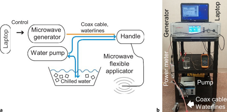
Figure 1 illustrates components of the ablation system used for navigation bronchoscopy-guided microwave ablations in normal porcine lung in vivo. The microwave applicator is a 1.1-m-long, 1.9-mm O.D. flexible catheter, suitable for delivery via the 2.6-mm instrument channel of a 6-mm O.D. flexible bronchoscope (Olympus BF 1T160) or a 2.0-mm instrument channel of a diagnostic bronchoscope such as Olympus BF 160. The applicator includes a coaxial monopole antenna with a short balun, which is integrated within concentric PTFE tubing to enable closed-loop circulation of cooling water. A peristaltic pump (Cole Parmer® Masterflex® L/S™ economy drive 7015-20) was employed to circulate chilled water (4°C) from a thermally insulated reservoir through the catheter. Considering only attenuation loss within the coaxial cable, we estimate ∼53% of incident microwave power at the catheter input is transferred to the tissue, with further losses possible due to impedance mismatches during ablation procedures.
Fig. 1.
a Block diagram sketch of the 2.45 GHz, water-cooled, microwave ablation platform and (b) photograph of the assembled system including the microwave generator, pump for circulating coolant, and control computer.
Microwave power is transferred from the microwave generator (GMS 200 W SAIREM, France) to the flexible applicator via a 6-ft-long coaxial cable RG393 (Pasternack, Inc.). Considering an estimated cable attenuation of 0.12 dB/ft at 2.45 GHz, this results in ∼84% of the applied input power from the generator arriving at the proximal connector of the ablation applicator. With further attenuation along the 1.1-m-long ablation catheter, approximately 39–42% of the generator power is transferred to tissue. All experimental power levels reported in this paper are assessed at the proximal connector of the microwave applicator.
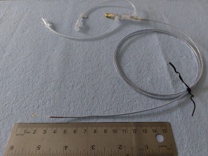
Compared to the applicator from our previous study [19], the newer catheter design, which is shown in Figure 2, incorporated thermal and electromagnetic considerations to allow for considerably higher power levels. From an electromagnetic perspective, the antenna balun for longitudinally constraining ablation dimensions along the catheter axis was optimized, so as to be suitable for high-power ablation. Further, catheter materials and dimensions for circulating cooling water to limit peak tissue temperature and maintain the structural integrity of the applicator were revised, while ensuring flexibility.
Fig. 2.
High-power ablation catheter design employed for in vivo experimental studies.
Microwave Ablation Procedures in Porcine Lung in vivo
Microwave ablations were performed in normal porcine lung using a bronchoscopic approach, similar to prior studies [19]. Briefly, each animal was subjected to pre-procedural, and post-procedural CT imaging as well as bronchoscopic microwave ablation with virtual bronchoscopy guidance at several chosen lung sites.
Pre-procedural planning CT was acquired and used to reconstruct a 3D virtual model of the lung airways and vessels, as well as to identify regions of lung parenchyma suitable for ablation. The planned target sites for ablation were defined as mutually non-overlapping spheres with 3 cm diameter (according to the maximum expected ablation size) and chosen in the peripheral regions of each lung lobe such that the center of the target was at least 15 mm away from closest point of the lung boundary to mitigate the chance of pneumothorax caused by thermal damage to the pleura. The central zone of the lungs was avoided due to the proximity of larger heatsinks like airways and vessels with the potential to significantly disrupt the ablation shape.
CT images (GE Brightspeed, 16 slices, 120 kV, 240–300 mA, 0.625 mm slice thickness) of inflated lungs were acquired with anesthetized pigs positioned in a dorsal recumbency. Pigs were manually ventilated with approximately 15 rapid breaths to induce apnea and maintained at a positive end-expiratory pressure of 12 cm H2O during image acquisition.
During ablation procedures, the Archimedes platform (Broncus Medical, San Jose, CA, USA) was employed to provide image guidance to the operator during the delivery of the bronchoscope to the planned point of entry (POE) into the lung parenchyma. The selection criteria for the POE were (1) distance to the planned target site less than 5 cm, (2) penetration angle between needle axis and airway wall higher than 30°, and (3) absence of vessels between POE and ablation target.
The bronchoscopy-guided ablation procedures were performed by a board-certified large animal veterinary surgeon (W.L.B.). Anesthetized pigs were placed in dorsal recumbency, an Olympus BF-1T160 bronchoscope was placed into the trachea, and the Archimedes navigation system was used to provide image guidance to the surgeon during navigation of the bronchoscope towards intended target locations. The flexible Archimedes sheath with stylet was deployed through the working channel of the bronchoscope to the POE identified during treatment planning. The airway wall was then punctured at the POE with an 18-gauge flexible coring needle (FlexNeedle, Broncus Medical, San Jose, CA, USA). After penetrating the needle through the airway wall, the flexible Archimedes sheath was advanced over the FlexNeedle and into the lung parenchyma. Then, the FlexNeedle was withdrawn from the lumen of the Archimedes sheath, and a blunt stylet was introduced into the sheath’s lumen. The sheath with the stylet was then advanced into the parenchyma to the ablation target site under Archimedes virtual bronchoscopy and fluoroscopy guidance. The stylet was then removed and replaced by the percutaneous microwave ablation (MWA) applicator. Real-time fused fluoroscopy was used to estimate the position of the applicator.
After confirming appropriate microwave applicator positioning using fluoroscopy in multiple planes, water flow through the applicator was initiated and followed by microwave ablation. Two ablative doses were applied: 90 W for 5 min (n = 3) and 120 W for 10 min (n = 5). These power levels refer to power as estimated at the applicator input port, and translate to 47.7 W and 63.6 W, respectively, at the applicator radiating tip.
Animals and Anesthesia
We performed a total of eight microwave ablations under Archimedes image guidance in two domestic pigs (weight: 104, 112 lb) in a study approved by the Kansas State University’s Institutional Animal Care and Use Committee (IACUC). Pigs underwent CT imaging on 2 (female, further referred to as Pig 1) and 3 (male, further referred to as Pig 2) days prior to the bronchoscopic MWA procedure to generate a virtual map of the lungs, airways, and blood vessels within the Archimedes virtual bronchoscopy system. The virtual map was subsequently used in selecting POE and safe paths for transparenchymal MWA procedures. Animals were under anesthesia for both imaging and ablation procedures. Anesthesia was induced with Telazol™ (4.4 mg/kg, intramuscular) and xylazine (2.2 mg/kg, intramuscular), atropine sulfate (0.05 mg/kg, intramuscular) was administered to aid intubation, and 1.5–30% isoflurane was administered in 100% oxygen to maintain anesthesia. Pigs were ventilated by intermittent positive pressure ventilation (I:E ratio 1:2, RR 16−20/min, VT 60–90 mL) to maintain end-tidal CO2 (EtCO2) less than 55 mm Hg. ECG, EtCO2, SpO2, and respiratory rate were continuously monitored. After completion of post-procedure imaging, animals were euthanized under anesthesia with 10 mL pentobarbitol (390 mg/mL, intravenous).
A maximum of n = 4 ablations were performed in each pig, for a total of 8 ablations across 2 pigs. Half (n = 4) of the ablations were performed with the applicator wedged tightly within the periphery airway wall, while the remaining half were performed after puncturing the airway wall and delivering the ablation into the lung parenchyma via a tunnel. We evaluated high (120 W for 10 min) and low (90 W for 5 min) microwave energy doses in this study to determine the range of energies that can safely be used for MWA treatment in a live porcine model.
Analysis of in vivo Ablation Zone Extents
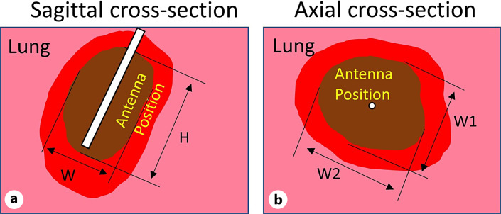
Following completion of the ablation procedures, chest CT scans were acquired before and following administration of a contrast agent (Omnipaque 300, 60 mL, ear vein injection). Anesthetized animals were euthanized following CT imaging, a postmortem examination was performed and lungs were removed for examination within 2 h of euthanization by a board-certified anatomic pathologist (M.A.H.). Areas of ablation were collected, and ∼1 cm thick slab sections, which included central zones of ablation and surrounding parenchyma, were fixed in 10% neutral buffered formalin and placed in triphenyl tetrazolium chloride (TTC) viability stain to highlight areas composed of cells with intact mitochondrial function. Fixed tissue specimens were processed into paraffin blocks, sectioned at 5 μm, placed on glass slides, and stained with hematoxylin and eosin, following standard methods, for light microscopic examination. The minimum and maximum diameters of each ablation zone (“brown zone”) within TTC-stained tissue sections were measured, as in our previous study [19]. Figure 3 illustrates sagittal and axial ablation zone measurements taken on TTC stained slab sections; ablation zones reported in this manuscript are the “brown zone” in TTC stained tissue (i.e., do not include the hyperemic region on the ablation zone periphery). Ablation zone dimensions W1, W2, and H were also manually measured from CT images of respective ablations by a board-certified veterinary radiologist with >30 years of experience (D.L.B.).
Fig. 3.
Extents of ablation zones on TTC stained sections noted on sagittal (a) (plane along applicator axis) and axial (b) (perpendicular plane to applicator axis) sections. Dimensions of ablation zones noted in this manuscript correspond to the “brown zone,” where W stands for observed ablation diameter in sagittal plane, W1/W2 denotes minimum/maximum observed ablation diameter in axial plane, and H stands for ablation height.
Results
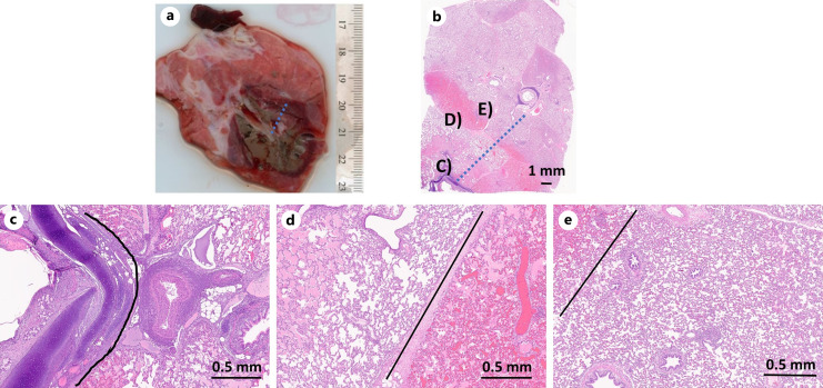
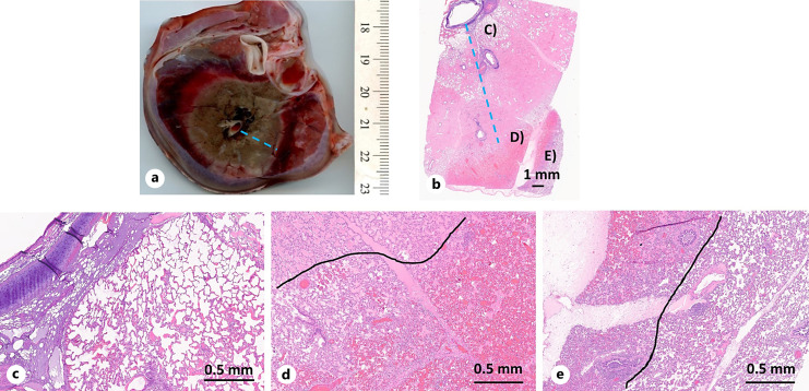
A total of eight ablations were performed in two pigs, with a maximum of four ablations in each pig. Table 1 provides the measurements of ablation zone dimensions on all zones that were observed on gross examination following staining. It was only possible to slab section the tissue along an axial or sagittal cut. For those ablation zones for which axial sections were obtained, only dimensions W1 and W2 could be measured; on sagittal sections, only W and H could be measured (see Fig. 3). As listed in Table 1, two of the 10 min ablations were stopped prematurely (one after 4 min 20 s, the other after 8 min 48 s) due to technical challenges with the catheter. Figures 4 and 5 illustrate gross and histologic changes identified in areas of lung tissue ablated with lower (90 W, 5 min) or higher (120 W, 10 min) applied power/duration combinations, respectively. TTC stain delineated the zones of ablation (brown zones) from surrounding tissue that maintained mitochondrial activity (Fig. 4a, 5a). Histologic examination of H&E-stained sections identified three distinct tissue zones. These zones, from the center (site of probe) outward to histologically normal tissue, include a central zone of necrosis with loss of architecture, zone of thermal fixation in which tissue architecture remains, erythrocytes are absent, and varying amounts of proteinaceous material (edema) are within alveolar spaces, and a zone of hemorrhage which separates the thermal fixation zone from histologically normal tissue. The average achieved maxima of ablation zone diameters W1 and W2 (Table 1), observed on gross slab section examination (“brown zone”), are significantly larger compared to the average W2 dimensions reported in our previous study [19]. Their relative differences to prior W2 dimensions (for 60 W, 5 min) are 54% and 131% for 90 W, 5 min and 120 W, 10 min, respectively.
Table 1.
Ablation zone measurements as identified in tissue cross sections on gross slab section examination and CT imaginga
| Tissue cross section | CT imaging | Route, tunnel length | Pig, lobe location | ||||||
|---|---|---|---|---|---|---|---|---|---|
| W | H | AR [–] | W1 | W2 | H | AR [–] | |||
| W1 | W2 | ||||||||
| 90 W, 5 min | |||||||||
| 2.4b | 3.2 | 0.75 | 3.1 | 3.3 | 4.1 | 0.77 | EB | Pig 2, right superior | |
| 2.1 | 3.4 | 0.65 | 3.0 | 3.2 | 4.1 | 0.76 | TB, 3 cm | Pig 2, left inferior | |
| 1.6 | 3.7 | 0.43 | 2.1 | 2.6 | 4.7 | 0.50 | TB, 3 cm | Pig 2, left middle | |
| 2.0±0.3 | 3.4±0.2 | 0.6±0.2 | min 2.7±0.4 | 4.3±0.3 | 0.7±0.2 | ||||
| max 3±0.3 | |||||||||
| all 2.9±0.4 | |||||||||
| 120 W, 10 min | |||||||||
| 2.7b | 3.2 | – | – | 3.8 | 4.2 | 5.1 | 0.78 | EB | Pig 2, right middle |
| 3.5 | 5.2 | 0.67 | 3.5 | 4.2 | 4.8 | 0.80 | TB, 4 cm | Pig 1, left superior | |
| 2.4c | 2.5 | – | – | 3.3 | 3.5 | 5.3 | 0.64 | EB | Pig 1, left inferior |
| 2.1d | 2.9 | – | – | 2.6 | 2.6 | 3.2 | 0.81 | EB | Pig 1, right inferior |
| 3.1±0.4 | 5.2 | 0.67 | min 3.3±0.4 | 4.6±0.8 | 0.8±0 | ||||
| max 3.6±0.6 | |||||||||
| all 3.5±0.6 | |||||||||
| 60 W, 5 min (from Sebek et al. [19], presented for comparison) | |||||||||
| min 1.1±0.3 | – | – | min 1.7±0.4 | 2.6±0.4 | 0.80 | ||||
| max 1.3±0.1 | max 2.4±0.5 | ||||||||
All dimensions are in cm, except for axial ratio (AR), which is dimensionless.
EB, endobronchial; TB, transbronchial.
aOnly W1 and W2, or W and H could be measured on gross tissue cross sections, depending on the orientation of the section relative to the ablation catheter insertion (see Fig. 3).
bCT image shown in Figure 6.
cAblation stopped after 4 min 20 s, device handle over-heated; not accounted for in summary statistics.
dAblation stopped after 8 min 48 s, device leak observed, dimension W1 affected by lung boundary and not accounted for in summary statistics.
Fig. 4.
Lung following in vivo ablation with 90 W applied for 5 min. a Gross lung section across ablation zone (TTC stain). b Histologic section (H&E stain) corresponding to gross lung section with distinct tissue transition zones (c–e). c Transition between necrosis (left) and thermal fixation (right). d Transition between thermal fixation (left) and hemorrhage (right). e Transition between hemorrhage (upper right) and normal tissue. Black lines delineate transitions.
Fig. 5.
Lung following in vivo ablation 120 W applied for 10 min. a Gross lung section across ablation zone (TTC stain). b Histologic section (H&E stain) corresponding to gross lung section with distinct tissue transition zones (c–e). c Region of necrosis. d Transition between thermal fixation (left) and hemorrhage (right). e Transition between hemorrhage (left) and normal tissue (right). Black lines delineate transitions.
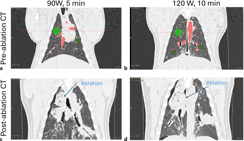
Figure 6 shows CT images taken before ablation (a, b) and images taken immediately after ablation (c, d). Pre-ablation CT images also include chosen target locations (green circles) and segmented vessels from Archimedes planning platform.
Fig. 6.
CT images of target sites before (a, b) and after (c, d) ablations, which are shown in Fig. 4 (90 W, 5 min) (a, c) and Fig. 5 (120 W, 10 min) (b, d). Green circles denote chosen target sites and red areas stand for segmented vessels by Archimedes planning platform.
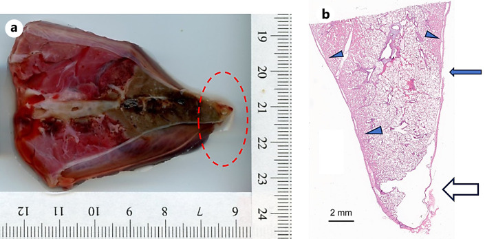
In the first pig (female), a few minutes after withdrawing the ablation catheter and bronchoscope at the completion of the fourth ablation procedure, the pig developed an abnormal cardiac rhythm and died prior to CT imaging. A pneumothorax was identified on postmortem CT imaging and confirmed on postmortem gross examination, and it was visually observed that for the third ablation, the ablation catheter was abutting the pleura, even though the planned virtual target was selected to be ∼15 mm from the pleural surface. Light microscopic examination of the third ablation site, at the site of visceral pleura rupture (apex of right caudal lobe), revealed an air-filled space that subtended a focally extensive area of thin and frayed pleura with fibrin and embedded degenerate leukocytes; extending proximal to this, clear space (air) separated the pleural from the pulmonary parenchyma (dissecting air) and a focal rupture in the pleura was identified (see Fig. 7). This underscores the need for verification of ablation catheter positioning with 3D intra-procedural imaging (e.g., CBCT) prior to initiating ablation. In the second pig, all four ablations were performed successfully, CT imaging was performed following ablation, and the animal was euthanized as per protocol. One of the 120 W, 10 min ablation zones in pig 1 could not be found on gross examination due to the lung shrinking following the pneumothorax.
Fig. 7.
a Gross section of ablation zone which resulted in pneumothorax. b Histologic section (H&E stain) corresponding to gross lung section at the site of pleural rupture. Apex of the lobe has a clear space (∼0.5 cm) that subtends a focally extensive area of thin and frayed pleura with fibrin and embedded degenerate leukocytes adhered to the surface (open arrow). Tear in the pleura (closed arrow). Parietal pleura separated from pulmonary parenchyma by clear space (arrow heads).
Discussion
In a prior feasibility and safety microwave ablation treatment study [19], we demonstrated the technical feasibility of delivering microwave ablation using low power (60 W at the catheter input) with a transbronchial approach guided by virtual bronchoscopy in an in vivo porcine model using a custom 2.45 GHz water-cooled ablation catheter. The present study aimed to expand on the prior results by enhancing the catheter design to accommodate higher power levels, requisite for achieving ablation zones needed to create ablation zones in the range of 10–30 mm in diameter. The experiments in porcine lung in vivo demonstrated the ability to create ablation zones with average axial ablation diameters in the range 20–31 mm with applied power of 90 W for 5 min and 120 W for 10 min (Table 1), respectively. These data demonstrated the effectiveness of the improved catheter design, which allows for high power level application, to produce ablation zones larger than the maximum ∼13 mm ablation diameter from the prior study.
While the ablation zones segmented from CT images allowed for simultaneous estimation of all dimension measurements W1, W2, and H, these values can be affected by artifacts commonly seen in immediate post-procedural CT images. Mainly, hemorrhagic regions or local bleeding, which typically encompass newly induced ablation zone in living tissue, have similar HU intensity as the ablation zone itself. The resulting ablation dimension measurements might be therefore larger than the actual brown zone measured from tissue cross sections on pathology. This can be seen in our data as diameter W as seen on CT images is on average bigger than W from tissue cross section by 31% for 90 W, 5 min and by 13% for 120 W, 10 min, respectively. These artifacts on CT images can also potentially explain the discrepancy in ablation dimensions increase when switching from energy dose 90 W, 5 min to 120 W, 10 min, i.e., average 55% increase in W for ablations identified on tissue cross section versus only ∼21% average increase for ablations identified from CT images. CT images taken after some time (2 weeks) to allow healing of temporary tissue states around induced ablation can provide cleaner ablation estimates.
The first pig (female) expired shortly after removing the bronchoscope following all ablations and prior to acquiring the post-ablation CT. A tension pneumothorax was observed on CT imaging, and on gross postmortem examination, it was confirmed that the ablation catheter track was abutting the pleura (<5 mm from the pleural surface) and likely led to the pneumothorax. Notably, there were technical issues during calibration with the navigation system for this study, and these may have contributed to the inaccurate placement and estimation of the catheter tip position relative to the pleural surface. While virtual bronchoscopy provides considerably more 3D information and guidance than fluoroscopy alone, this observation underscores the need for 3D intra-procedural imaging (e.g., CBCT) to confirm the ablation catheter position and sufficient distance from critical structures, prior to initiating the ablation. Additionally, the use of endoluminal robotic systems for delivery of the ablation catheter, as recently demonstrated in an in vivo porcine model [20], to the desired target and hold the bronchoscope position within the target site may also contribute to the safe, accurate, and consistent delivery of ablation treatment to lung tumors.
Similar to our previous study, in which lower power levels were applied [19], zones of distinct histopathologic change were noted with the higher power applied in this study. In this study, we describe 3 zones, characterized by necrosis with loss of architecture closest to the probe (zone 1), maintenance of general architecture with edema and loss of red blood cells (zone 2), and marked vascular congestion and hemorrhage (zone 3). Peripheral to zone 3, lung tissue resumes a normal histologic appearance as viewed by light microscopy. Within a few sites of ablation, the margin between thermal fixation and hemorrhage was seemingly tracked along interlobular septae (visible in Fig. 4d).
The results of this study demonstrated the ability to use high-power microwave ablation to generate ablation zones up to 3 cm in ablation diameter in normal porcine lung in vivo. Additionally, it highlighted the importance of accurate positioning as well as confirmation using intraoperative 3D imaging of the device position prior to initiating the ablation. The extent of ablation zones reported in the present study is comparable to those reported in other recent studies with flexible microwave ablation catheters [11, 20]. Further studies of the reported ablation catheter and system and procedure in a survival model are needed to more carefully evaluate histologic characteristics of the ablation zone, procedure safety, and the wound healing response following transbronchial microwave ablation in the lung.
Acknowledgments
Author Abbe Smith was not available to confirm co-authorship, but the corresponding author Punit Prakash affirms that author Abbe Smith contributed to the paper, had the opportunity to review the final version to be published, and guarantees author Abbe Smith co-authorship status and the accuracy of the author contribution and conflict of interest statements.
Statement of Ethics
All experiments were conducted under a protocol approved by the Kansas State University Institutional Animal Care and Use Committee (protocol 4450).
Funding Sources
This work was supported by NIH grant R01CA218357.
Conflict of Interest Statement
J.S., W.L.B., M.A.H., N.H., D.S.H., D.S.B., R.A.M., and S.L. have no relevant disclosures. S.G. and H.W. were employees of phenoMapper at the time of this study. A.S. and K.-C.Y. were employees of Broncus Medical Inc., at the time of this study. P.P. reports grants from the National Institutes of Health during the conduct of the study; and grants from the National Institutes of Health, National Science Foundation, and Jano.Life, outside the submitted work. In addition, P.P. is an inventor on issued patents and pending patent applications on microwave ablation technology.
Author Contributions
J.S.: study design, device and system design, data collection, analysis, and writing. S.G.: device fabrication, data collection, and analysis. W.L.B., D.S.B, D.S.H., and M.A.H.: animal procedures, data collection, analysis, and writing. N.H. and A.S.: animal procedures. K.-C.Y.: image analysis. R.A.M. and S.L.: study design and analysis. H.W.: study design, image analysis, and writing. P.P. study design, analysis, and writing. Furthermore, all authors were involved in the manuscript review.
Funding Statement
This work was supported by NIH grant R01CA218357.
Data Availability Statement
Datasets presented in this study are not publicly available since they are the subject of technology translation process but are available from the corresponding author upon reasonable request.
References
- 1. Sidoff L, Dupuy DE. Clinical experiences with microwave thermal ablation of lung malignancies. Int J Hyperthermia. 2017;33(1):25–33. [DOI] [PubMed] [Google Scholar]
- 2. De Baere T, Tselikas L, Catena V, Buy X, Deschamps F, Palussière J. Percutaneous thermal ablation of primary lung cancer. Diagn Interv Imaging. 2016;97(10):1019–24. [DOI] [PubMed] [Google Scholar]
- 3. Narsule CK, Sridhar P, Nair D, Gupta A, Oommen RG, Ebright MI, et al. Percutaneous thermal ablation for stage IA non-small cell lung cancer: long-term follow-up. J Thorac Dis. 2017;9(10):4039–45. [DOI] [PMC free article] [PubMed] [Google Scholar]
- 4. Ridge CA, Solomon SB. Percutaneous ablation of colorectal lung metastases. J Gastrointest Oncol. 2015;6(6):685–92. [DOI] [PMC free article] [PubMed] [Google Scholar]
- 5. Inoue M, Nakatsuka S, Yashiro H, Ito N, Izumi Y, Yamauchi Y, et al. Percutaneous cryoablation of lung tumors: feasibility and safety. J Vasc Interv Radiol. 2012;23(3):295–305. [DOI] [PubMed] [Google Scholar]
- 6. Ager BJ, Wells SM, Gruhl JD, Stoddard GJ, Tao R, Kokeny KE, et al. Stereotactic body radiotherapy versus percutaneous local tumor ablation for early-stage non-small cell lung cancer. Lung Cancer. 2019;138:6–12. [DOI] [PMC free article] [PubMed] [Google Scholar]
- 7. Brace CL. Radiofrequency and microwave ablation of the liver, lung, kidney, and bone: what are the differences? Curr Probl Diagn Radiol. 2009;38(3):135–43. [DOI] [PMC free article] [PubMed] [Google Scholar]
- 8. Jiang T, Zhao Q. Lung tumors laser ablation. Image-guid Laser Ablation. 2020:107–15. [Google Scholar]
- 9. Zhao Q, Tian G, Chen F, Zhong L, Jiang T. CT-guided percutaneous laser ablation of metastatic lung cancer: three cases report and literature review. Oncotarget. 2017;8(2):2187–96. [DOI] [PMC free article] [PubMed] [Google Scholar]
- 10. Chaddha U, Hogarth DK, Murgu S. Bronchoscopic ablative therapies for malignant central airway obstruction and peripheral lung tumors. Ann Am Thorac Soc. 2019;16(10):1220–9. [DOI] [PubMed] [Google Scholar]
- 11. Chan JW, Lau RWH, Ngai JCL, Tsoi C, Chu CM, Mok TSK, et al. Transbronchial microwave ablation of lung nodules with electromagnetic navigation bronchoscopy guidance–a novel technique and initial experience with 30 cases. Transl Lung Cancer Res. 2021;10(4):1608–22. [DOI] [PMC free article] [PubMed] [Google Scholar]
- 12. Ferguson J, Egressy K, Schefelker R, Thiel M, Thom M, Bissing J, et al. Bronchoscopically-guided microwave ablation in the lung. Chest. 2013;144(4):87A.23392731 [Google Scholar]
- 13. Sabath BF, Casal RF. Bronchoscopic ablation of peripheral lung tumors. J Thorac Dis. 2019;11(6):2628–38. [DOI] [PMC free article] [PubMed] [Google Scholar]
- 14. Yuan H-B, Wang XY, Sun JY, Xie FF, Zheng XX, Tao GY, et al. Flexible bronchoscopy-guided microwave ablation in peripheral porcine lung: a new minimally-invasive ablation. Transl Lung Cancer Res. 2019;8(6):787–96. [DOI] [PMC free article] [PubMed] [Google Scholar]
- 15. Pritchett MA, Reisenauer JS, Kern R, Wilson DS, Meyers EE, Szapary PO, et al. Novel image-guided flexible-probe transbronchial microwave ablation for stage 1 lung cancer. Respiration. 2023;102(3):182–93. [DOI] [PMC free article] [PubMed] [Google Scholar]
- 16. Ishiwata T, Motooka Y, Ujiie H, Inage T, Gregor A, Aragaki M, et al. Endobronchial ultrasound-guided bipolar radiofrequency ablation for lung cancer: a first-in-human clinical trial. J Thorac Cardiovasc Surg. 2022;164(4):1188–97.e2. [DOI] [PubMed] [Google Scholar]
- 17. Steinfort DP, Antippa P, Rangamuwa K, Irving LB, Christie M, Chan E, et al. Safety and feasibility of a novel externally cooled bronchoscopic radiofrequency ablation catheter for ablation of peripheral lung tumours: a first-in-human dose escalation study. Respiration. 2023;102(3):211–9. [DOI] [PMC free article] [PubMed] [Google Scholar]
- 18. Steinfort DP, Christie M, Antippa P, Rangamuwa K, Padera R, Müller MR, et al. Bronchoscopic thermal vapour ablation for localized cancer lesions of the lung: a clinical feasibility treat-and-resect study. Respir Int Rev Thorac Dis. 2021;100(5):432–42. [DOI] [PubMed] [Google Scholar]
- 19. Sebek J, Kramer S, Rocha R, Yu KC, Bortel R, Beard WL, et al. Bronchoscopically delivered microwave ablation in an in vivo porcine lung model. ERJ Open Res. 2020;6(4):00146-2020. [DOI] [PMC free article] [PubMed] [Google Scholar]
- 20. De Leon H, Royalty K, Mingione L, Jaekel D, Periyasamy S, Wilson D, et al. Device safety assessment of bronchoscopic microwave ablation of normal swine peripheral lung using robotic-assisted bronchoscopy. Int J Hyperthermia. 2023;40(1):2187743. [DOI] [PubMed] [Google Scholar]
Associated Data
This section collects any data citations, data availability statements, or supplementary materials included in this article.
Data Availability Statement
Datasets presented in this study are not publicly available since they are the subject of technology translation process but are available from the corresponding author upon reasonable request.


