Abstract
Recently, the integration of renewable energy sources, specifically photovoltaic (PV) systems, into power networks has grown in significance for sustainable energy generation. Researchers have investigated different control algorithms for maximum power point tracking (MPPT) to enhance the efficiency of PV systems. This article presents an innovative method to address the problem of maximum power point tracking in photovoltaic systems amidst swiftly changing weather conditions. MPPT techniques supply maximum power to the load during irradiance fluctuations and ambient temperatures. A novel optimal model reference adaptive controller is developed and designed based on the MIT rule to seek global maximum power without ripples rapidly. The suggested controller is also optimized through two popular meta-heuristic algorithms: The genetic algorithm (GA) and the whale optimization algorithm (WOA). These meta-heuristic approaches have been exploited to overcome the difficulty of selecting the adaptation gain of the MRAC controller. The reference voltage for MPPT is generated in the study through an adaptive neuro-fuzzy inference system. The suggested controller’s performance is tested via MATLAB/Simulink software under varying temperature and radiation circumstances. Simulation is carried out using a Soltech 1sth-215-p module coupled to a boost converter, which powers a resistive load. Furthermore, to emphasize the recommended algorithm’s performance, a comparative study was done between the optimal MRAC using GA and WOA and the conventional incremental conductance (INC) method.
Keywords: Maximum power point tracking, Photovoltaic systems, Model reference adaptive control, Adaptive neuro-fuzzy inference system, Genetic algorithm, Renewable energy, Convergence analysis
Subject terms: Energy science and technology, Engineering, Mathematics and computing
Introduction
Among the most disturbing topics in the status quo is the spread of environmental pollution worldwide1. The primary factor that causes ecological pollution is fossil fuels because of their use in energy production and industrial fields2,3. No doubt, finding a new energy source has become necessary to reduce the use of fossil fuels and their emissions4,5. Among the robust proposed solutions is renewable energy, like solar and wind energy. The demand for renewable energy as an alternative source is growing6,7. Solar energy is one of the most popular sources because it is limitless and spotless to produce energy without harmful emissions8,9. Depending on the photovoltaic (PV) effect, a solar cell converts the irradiation into electrical energy through many physical processes10. Even though all the PV cells have enticing features, their energy conversion efficiency is still relatively low11. Figure 7 shows the power-voltage (P–V) diagram for a PV array, demonstrating the variation of the PV power concerning PV voltage under various amounts of temperature and irradiance. It is clear that only under steady-state environmental conditions does the PV cell provide the highest operating point, called the maximum power point (MPP)9,12,13. To achieve this point, we must employ a critical device known as a maximum power point tracking (MPPT) controller14. Today, researchers worldwide seek to develop and create new methods to extract as much power from PV panels15,16. In the literature8,17,18, we can find various classifications of these MPPT techniques.
Figure 7.
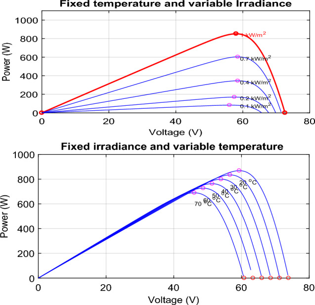
The characteristic curve of a photovoltaic module under varying environmental conditions.
Among the classical MPPT techniques, we mention Perturb and observe P&O19–21, Incremental Conductance (INC)22–24, and Hill Climbing (HC)25–27. However, each technique has specific strengths and weaknesses; for example, P&O and HC are simple and require fewer sensors than other techniques28,29. In30, a modified perturbation and observation have been proposed to avoid the drift due to the traditional P&O’s incorrect choice. The INC algorithm was introduced to resolve P&O issues. In31, an improved MPPT strategy based on INC is suggested to increase productivity and efficiency under fast-changing irradiance. Ref32, has been proposed an improved P&O using simulated annealing (SA) algorithm, the proposed algorithm exhibits better performance in varying weather conditions and partial shading Nevertheless, the classical MPPT methods and even those developed are still weak under varying environmental conditions and rapid oscillations around the maximum power.
In terms of dynamic weather-varying conditions, intelligent MPPT techniques33 are often used, including fuzzy logic control (FLC)34,35, artificial neural networks (ANN)36–38, adaptive neuro-fuzzy inference systems (ANFIS)39, sliding mode control40, and Gauss–Newton method-based MPPT34. These techniques are very efficient and faster for tracking the MPP. Nevertheless, they require many data sets to train and improve tracking accuracy, especially ANN and ANFIS-based MPPT; their implementation can be challenging.
Recently, bio-inspired algorithms like Particle Swarm Optimization (PSO)41, Genetic Algorithm (GA)42, Grey Wolf Optimization (GWO)43, and Whale Optimization Algorithm44 have been widely used in PV systems to determine the maximum power point, especially under partial shading conditions45. In46 a new MPPT called the slime mold golden sine algorithm was proposed in order to address the partial shading problem, the proposed SMGSA method exhibits superior effectiveness and enhancement. Most of these strategies follow an identical sequence or procedure to accomplish optimization47,48. Although bio-inspired solutions can effectively handle the challenge of partial shading, their efficacy depends entirely on the parameters chosen and the starting conditions49.
Combining bio-inspired algorithms with other MPPT approaches can overcome this restriction in bio-inspired algorithms. In50, an invented P&O with adaptive variable step size based on a PID controller optimized using the Genetic Algorithm was introduced. It shows less oscillation around the MPP and improves efficiency. Ref.51 has suggested a fuzzy logic controller optimized through the cuckoo strategy optimization approach (COA-FLC) for Maximum Power Point Tracking (MPPT) under various meteorological conditions. This COA-FLC has improved the convergence time and minimized the output ripple power. A fractional order based MPPT enhanced using different metaheuristic techniques was suggested in52, The results obtained demonstrated a high level of accuracy and increased robustness.
To avoid such improbable and substantial variations during the transitory phase, researchers proposed a two-level MPPT control architecture53. In54, the ripple correlation control algorithm was the initial loop of control, while the model reference adaptive controller MRAC was the second. The separation of these control algorithms results in the attainment of MPPT while ensuring the entire system’s stability. Another solution is described in55; an improved model reference adaptive controller was associated with incremental conductance. A set of tests and simulations using PSIM and experimental tests are employed to verify the effectiveness of the suggested methodology. However, most plants have PV systems and boost converters, mathematically modeled as second-order systems. Indeed, the performance of traditional MRAC tracking systems could be better for second-order systems. To improve MPPT performance, a novel MRAC structure has been expanded from the first to the second order56.
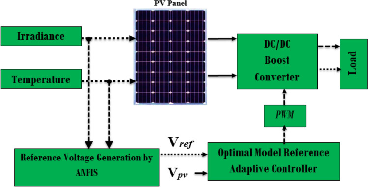
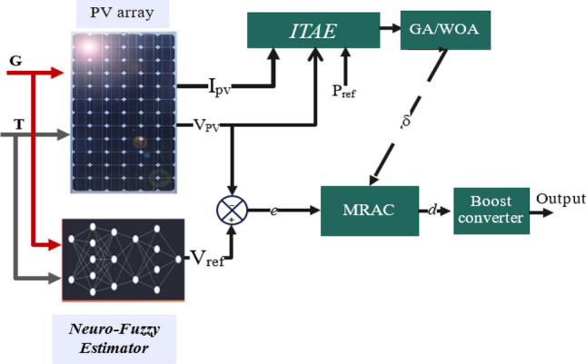
Nevertheless, one of the significant issues caused by non-linearity is determining MRAC adaptation gains according to specific methods. As described in references57,58, the authors investigated the influence of changing the adaptation gain on the overall system’s performance, including the time response and the oscillation in the response. In this article, meta-heuristic algorithms have been used to overcome this difficulty. Two optimization techniques are applied to tune the parameters of MRAC and improve its dynamic performance, namely the genetic algorithm (GA) and the whale optimization algorithm (WOA)59. In addition, an adaptable Neuro-Fuzzy Inference System (ANFIS) has been employed to produce voltage references for maximum power capacity, which a designed controller subsequently tracks; Fig. 1 illustrates the block diagram of the developed system.
Figure 1.
The proposed MPPT block diagram for the PV system.
The rest of this paper is organized as follows: Section “Mathematical modeling of photovoltaic array” describes a photovoltaic array's mathematical modeling and the boost converter’s mathematical representation. The neuro-fuzzy network and the proposed optimal model reference adaptive controller, OMRAC, are presented in Section “Dynamics modeling of the DC–DC boost converter”. Section “Proposed MPPT” contains the simulation results, discussion, conclusion, and future work.
Mathematical modeling of photovoltaic array
Single diode model
Several mathematical models illustrating solar panels' operation and performance are documented in the literature. Indeed, real-time simulation requires equivalent circuit modeling of PV cells. The most popular approximate equivalent model researchers use is the single-diode model, as presented in Fig. 2. The used circuit consists of at least four components: a current source IPh, a diode D, a parallel resistor Rp, and a series resistor Rs.
Figure 2.
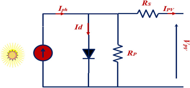
PV cell circuit using a single diode model.
According to the single diode equivalent model of the PV cell presented in Fig. 2, the output current IPV can be described as follows60.
| 1 |
The reverse saturation current of the cell is referred to as Irs. V denotes the voltage of the cell, whereas Ns indicates the number of PV cells linked in series at the same time. Np indicates the number of photovoltaic cells linked in parallel. K represents the Boltzmann constant, q symbolizes an electron’s charge, T denotes Kelvin’s temperature, and A represents the diode ideality constant. Based on Eq. (2), the irradiance of the sun E and the ambient temperature T are two of the main factors determining the IPh.
| 2 |
Ki represents the short-circuit current, T denotes the temperature coefficient of the cell, Isc is the short-circuit current, and E represents the variation in solar radiation. Equation (3) gives the saturation current in cell Irs. A strong correlation exists between temperature and saturation current61,62.
| 3 |
Irr: represents the reverse saturation corresponding to Tr; Tr: is the cell reference temperature; EG: is the band-gap energy of the semiconductor used in the cell.
Triple diode model
The PV cell scheme based triple diode model is illustrated in Fig. 3. This model taken into consideration two additional diodes as in the single diode model63,64. The expression of the output current can be given as following65.
| 4 |
where and denoted to the reverse saturation current of each diode.
Figure 3.
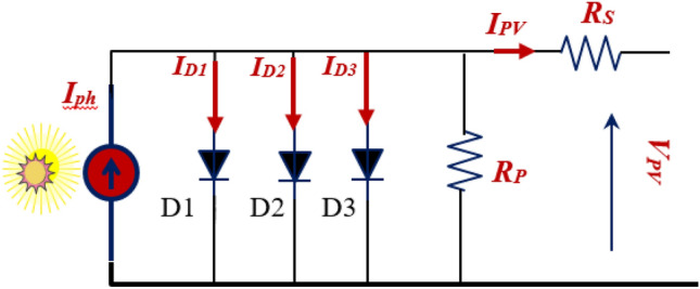
PV cell circuit using triple diode model.
Dynamics modeling of the DC-DC boost converter
A traditional MPPT algorithm relies on Eq. (4) to determine the converter's duty cycle when the system is stable. On the other hand, the MPPT controller needs to consider the dynamics related to the duty cycle d and the PV voltage VPV to optimize transient responses66,67. When the duty cycle is adjusted to reflect varying environmental circumstances, the MPPT controller should remove any transient fluctuations in the PV voltage68–70.
| 4 |
As suggested in71,72, a small signal model of the studied system was considered (Fig. 4) in order to make it easier to analyze how the system responds to changes over time. A resistor R with a small signal PV voltage represents the solar array V̂pv and current I ^pv throughout its terminals, while battery storage represents the load RO. By ignoring the battery load, the transfer function between the duty cycle d ^(s) as an input and the array voltage V ^pv(s) as an output of the system can be described as following72:
Figure 4.
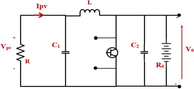
PV small signal model coupled to the boost converter.
Where f (D) is the correlation between a boost converter's voltage at the output array Vo and the operating duty cycle D.
| 6 |
The first derivation of Eq. (6) can be expressed by:
| 7 |
By inserting Eq. (7) into Eq. (5), we can obtain:
| 8 |
The negative sign in (8) implies that reducing the duty cycle d(s) causes the array voltage to increase. The transfer function depicted previously is derived from a linearized form73. Noteworthy is that C1 and L are identified, while R is unknown. The PV system's operating point (particularly the parameter R) fluctuates as ambient circumstances change quickly74,75. The value of R may be estimated by calculating the slope of the line tangent to point A on the I–V curve shown in Fig. 5 and then taking the inverse of that slope.
| 9 |
Figure 5.
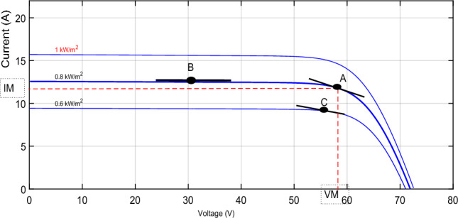
I-V curve of a solar array while changing R.
Proposed MPPT
The proposed MPPT technique in this paper can be divided into three main steps, as depicted in Fig. 6. The first objective is maintaining a constant reference voltage (Vref) from the PV module output using an adaptive neuro-fuzzy controller under fluctuating environmental circumstances.
Figure 6.
Block diagram of the suggested MPPT technique.
The ANFIS controller employs a relationship between VMPP and (irradiance and temperature) to supply reference peak power voltage. This reference value is compared with the value Vpv to provide an error value sent to the proposed MPPT's second stage. During the second control stage, the MRAC algorithm generates a control input that adjusts the DC–DC converter’s PWM signal. This paper also optimizes this controller using meta-heuristic optimization algorithms to ensure the most efficient dynamic performance of the system.
Reference voltage generation via adaptive neuro-fuzzy algorithm (ANFIS)
To guarantee maximum power from the PV panel to the load, the MPPT controller must constantly check the PV array output voltage. Several methods have been used for calculating or learning the PV array reference peak power voltage. For instance, artificial neural networks (ANN)60, regression plans49,76, Gaussian process regression (GPR)11, and adaptive neuro-fuzzy inference systems (ANFIS)39. This paper uses the Neuro-Fuzzy algorithm to generate/estimate the voltage reference VMPP for the proposed controller.
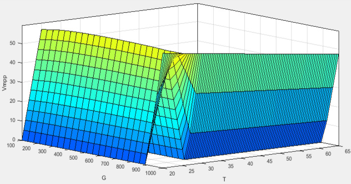
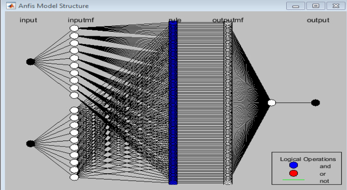
The curve of PV characteristic change under varying environmental conditions for every single temperature value (T) and irradiance (G) is presented in Fig. 7. The VMPP data was collected using MATLAB/Simulink by adjusting the temperature from 20 to 70 °C while keeping the irradiance constant at 1000 w/m2. Then, we set the temperature to 25°, whereas the irradiance has been varied from 100 to 1000 w/m2. Figure 8 presents the result of these data as a 3-D plane. The structure of the ANFIS model in MATLAB/Simulink for VMPP estimation is depicted in Fig. 9. The neuro-fuzzy estimator comprises temperature (T) and irradiance (G) inputs. The fuzzification layer, which includes ten triangular membership functions assigned to every variable, represents each rule in the output layer as a linear equation77,78.
Figure 8.
3D-plane.
Figure 9.
The architecture of NeuroFuzzy.
The ANFIS algorithm provides the reference voltage to the development controller. Then, the controller forces the output voltage to track the desired voltage to reach the maximum power point.
Model reference adaptive control (MRAC)
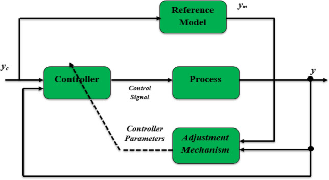
An adaptive controller is, intuitively, one that can adapt its actions based on variations in the process dynamics and the nature of the disturbance79. Several researchers have attempted to define adaptive control in the literature. As shown in Fig. 9, we will use the pragmatic approach in this research, which involves a controller with adjustable parameters and a mechanism that allows these parameters to be adjusted. MRAC systems are designed so that the plant model's output constantly tracks the reference model’s output80,81. The structure of the model consists of a PV system with a boost converter, represented by a second-order transfer function, as shown in Eq. (8). The voltage reference Vref produced by the first level (ANFIS estimator) is regarded as an input to the system, represented as u (t). In contrast, y (t) represents the output. The plant model can be rewritten in the following manner:
| 10 |
where
Figure 10.
The architecture of the model references adaptive control.
The reference model that guides how the process output should ideally react to the control signal u(t) is given in Eq. (11). Where ym is the desired output, Km represents a positive gain, and am and bm must be selected. The reference model thus offers the suggested solution.
| 11 |
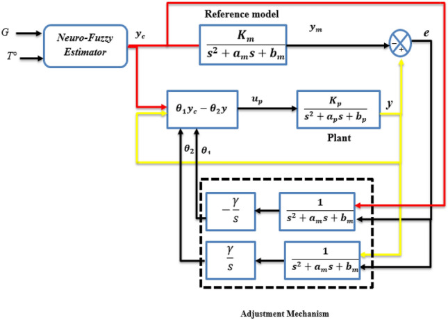
The controller architecture depicted in Fig. 10 illustrates the approach we will use to achieve the control objective. The control law is described as follows58:
| 12 |
where θ = [θ1, θ2] are the parameters of the controller vector, and ω is described as Y = [Yc, Y]T.
Figure 11.
Structure of the controller in the proposed OMRAC.
In order to design the adaptation mechanism, MRAC theory uses two basic mathematical techniques. The MIT rule (Massachusetts Institute of Technology) is known as the gradient approach and Lyapunov stability theory. This study has chosen the MIT rule to adjust the controller’s parameters as an adaptation mechanism. By using the MIT rule, the loss function is expressed by:
| 13 |
where e represents the error obtained by subtracting the plant y output value from the reference model output Ym.
| 14 |
A mathematical equation was developed for updating the parameter θ, based on the assumption that, if the purpose were to minimize the error-related cost, moving towards the negative gradient of J. where J is supposed to change proportionally to θ would be advisable. Therefore, the derivative of θ equals the negative variation in J. Based on the cost function selected above, the following result can be obtained:
| 15 |
Γ and ∂e/∂θ are the system’s adaptation gain and sensitivity derivative, respectively.
The transfer function between the input YC and the plant’s output y is given by:
| 16 |
Thus, Eq. (14) can be rewritten as follows:
| 17 |
According to (15), the sensitivity derivatives ∂e/∂θ1 and ∂e/∂θ2 can be described by:
| 18 |
In order to ensure a perfect tracking error from this close loop process, we will assume that the time behavior is the same as that of the reference model, as follows:
| 19 |
Therefore, based on the MIT rule, the control parameters are updated as follows:
| 20 |
The next step will be to tune the adaptation gain of the MRAC controller by employing two optimization techniques.
Optimization techniques
This section provides two optimizer algorithms, namely GA and WOA, to adjust the adaptation gains of the proposed MRAC structure. It is worth mentioning that both these methods are widely recognized and have been frequently employed for similar applications.
Genetic algorithm (GA)
GA is an algorithm that is based on the population genetics concept. Each solution represents a chromosome, while each parameter corresponds to a gene79,82,83. GA employs an objective (fitness) function to assess the fitness of every single population member. The approach of retaining the most efficient solutions in each generation and utilizing them to generate the following solutions renders this algorithm reliable and proficient in approximating the best possible solution for a given problem84,85. In order to update the population, three genetic processes (selection, crossover, and mutation) are applied after each chromosome has been evaluated through a cost function and assigned a fitness value51. The genetic algorithm (GA) uses a selection operator (Boltzmann selection, Tournament selection, Rank selection, etc.)86 to allocate probabilities to individuals based on their fitness values. It allows for the selection of individuals to create the next generation in proportion to their fitness values. Once individuals are chosen via a selection operator, they must be utilized to produce the new generation. The chromosomes from the male and female genes are merged to generate a novel chromosome; this operation in GA is called crossover87,88. Mutation operators maintain diversity by adding randomness. By using this operator, the GA algorithm avoids local solutions and prevents solutions from becoming similar43,79,89,90.
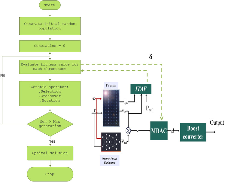
In this study, the cost function chosen to evaluate the result of each individual in the population is Integral Time Absolute Error (ITAE), where the error (e') can be obtained by subtracting the measured power from the maximum power (denoted Pref), as described in (21):
| 21 |
Figure 11 depicts the procedure for adjusting the parameters of the MRAC controller with GA, which can be outlined using a flowchart, as shown below:
Figure 12.
Block diagram for tuning of MRAC adaptive gain using GA.
Whale optimization algorithm
Highly intelligent and emotionally complex, whales have long captivated our imagination and inspired scientific research. Humpback whales are one of the most giant baleen whales. One of the most attractive aspects of humpback whales is their distinct hunting technique73. Based on this hunting technique, Mirjalili et al. introduced an innovative swarm intelligence algorithm called the Whale Optimization Algorithm (WOA)59. The humpback whale employs a distinctive hunting mechanism named the bubble net feeding method91. Noteworthy is that the bubble-net feeding method is a distinctive behavior exclusive to humpback whales. The hunting protocol of the humpback whale can be summarized in three steps:
Encircling Prey: Humpback whales can detect the whereabouts of their prey and surround them. In the Whale Optimization Algorithm (WOA), the precise location of the optimal design within the search space has yet to be discovered. Therefore, the algorithm postulates that the current foremost candidate solution is either the target prey or close to the optimal solution. Once the optimal search agent is identified, the remaining search agents adjust their positions toward the optimal search agent. This conduct is mathematically illustrated through the subsequent equations:
| 22 |
| 23 |
In the given equation, t denotes the present iteration, and serve as coefficient vectors, while X* represents a vector denoting the location of the best solution attained thus far. The process of determining the vectors and involves the following computations:
| 24 |
| 25 |
The vector gradually decreases linearly, starting by 2–0 over a series of iterations, whereas is a haphazard vector within the range [0,1].
Attacking Mechanism Using Bubble-Net: Two methods were developed to construct a mathematical representation for the bubble-net procedure of humpback whales: the Shrinking Encircling Mechanism and the Spiral Updating Position method92.
Shrinking encircling mechanism: This conduct can be achieved by decreasing the value of vector in the Eq. (24). It is essential to highlight that vector narrows the range of fluctuations in vector . Accordingly, the value of inside the range [−a, a]. By assigning random values to within the range of [− 1, 1], the search agent’s updated position can be between its original position and the current best agent’s position.
Spiral updating position: The method described in this approach involves computing the distance between a whale, which is positioned at coordinates (X, Y), and the location of its prey, which is located at coordinates (X*, Y*). Hence, a spiral equation is formulated to represent the helix-shaped movement of the whales. This spiral equation is expressed as:
| 26 |
While represents how the whale is far away from the prey, where the prey is the best result achieved thus far, the constant b defines the logarithmic spiral’s form. At the same time, l serves as a stochastic number within the interval of [− 1, 1].
In order to simulate the whales’ coordinated movements, it is postulated that there is an even chance of 50% to opt for either the shortening encircling mechanism or the spiral model while the optimization procedure, to alter the whales’ positions simultaneously20,56,93. The mathematical representation of this model is given by:
| 27 |
In the equation given, the variable p represents a random number within the range of [0 1].
Exploration Phase: During this phase, it is assumed that humpback whales search for prey randomly based on the positions of other whales. The model of this approach is expressed in this manner:
| 28 |
| 29 |
In the given equation, represents a whale’s haphazardly selected location data from the current iteration.
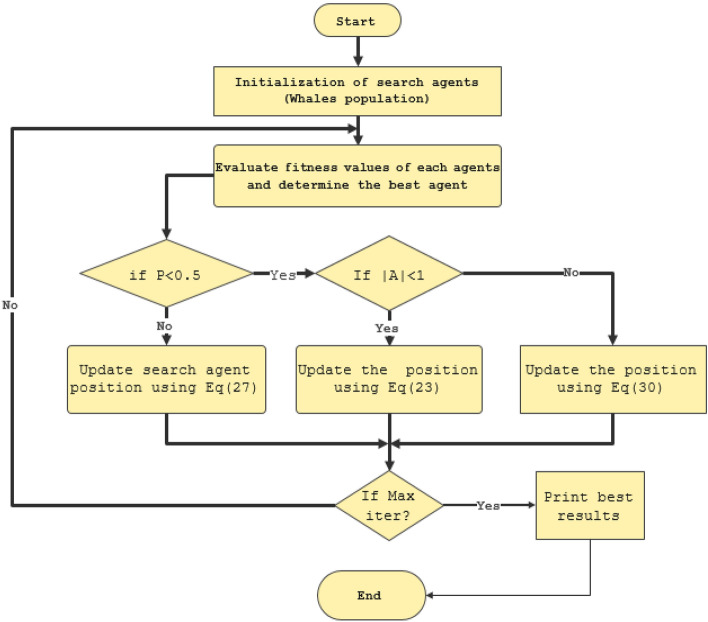
Using the same fitness function mentioned in (21), Fig. 13 illustrates the flowchart of the WOA.
Figure 13.
Whale optimization algorithm for tuning MRAC controller.
Simulation results and discussion
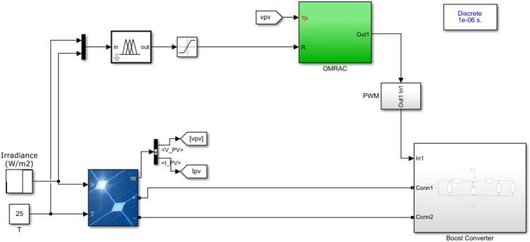
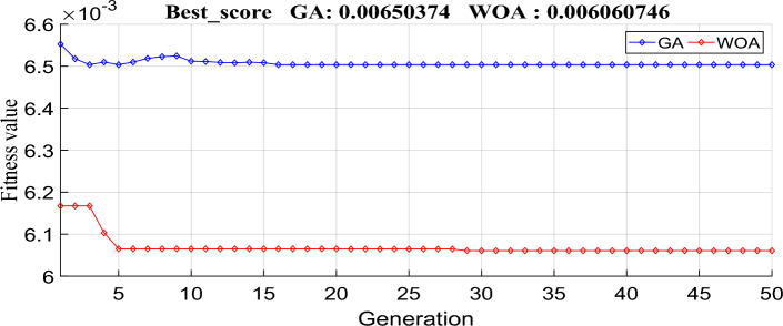
To check the effectiveness of the developed ANFIS-OMRAC algorithm-based MPPT, this section was dedicated to simulating and analyzing the entire model system with Simulink, as shown in Fig. 14. The photovoltaic solar panel chosen in this work is the Soltech 1STH-215-P type. PV specifications and the DC–DC boost converter parameters are listed in Table 1. Indeed, GA and WOA are used to tune the MRAC controller design parameters. GA and WOA require fewer input parameters, which is one of the most significant advantages of these algorithms. The specifications for each algorithmic parameter are defined in Table 2. The number of search agents (population size) is relatively small considering the real-time implementation so that the controller may be optimized as quickly as possible. Figure 15 illustrates the objective function performance during computation. The whale optimization algorithm converges faster than the genetic algorithm. The whale optimization algorithm was more effective than the genetic algorithm concerning the convergence rate and accuracy of results. The optimum MRAC adaptation gain appears in Table 3.
Figure 14.
Implementation of the proposed model using MATLAB/SIMULINK environment.
Table 1.
PV system characteristics.
| Parameters | Values |
|---|---|
| The Peak Power of the PV panel (W) | 213.15 |
| Open circuit voltage VOC (V) | 36.3 |
| Short circuit current ISC (A) | 7.84 |
| The voltage corresponding to the maximum power VMP (V) | 29 |
| The current corresponding to the maximum power IMP (A) | 7.35 |
| Parallel strings (NP) | 2 |
| Number of cells associated in Series (NS) | 2 |
| Input capacitor | 100 µF |
| Output capacitor | 100 µF |
| Inductor L | 2 mH |
| Restore load R | 25Ω |
| Frequency f | 20 kHz |
| Solver | 1 e-6 |
| Sample time | Ode 45 |
Table 2.
GA and WOA parameters.
| Genetic algorithm | |
|---|---|
| Population size | 15 |
| Crossover probability | 0.8 |
| Mutation function | Adaptive feasible |
| Population type | Double vector |
| Scaling function | Rank |
| Selection | Tournament |
| Maximum iteration | 50 |
| Whale optimization algorithm | |
|---|---|
| Population size | 15 |
| Maximum iteration | 50 |
| Cost function | ITAE |
Figure 15.
The performance of the objective function during the computation using GA and WOA.
Table 3.
The optimum MRAC controller gains.
| Parameters | Values | |
|---|---|---|
| Adaptation gain (γ) | 0.161386 | 0.235809 |
| Best score | 0.006503 | 0.006074 |
| Convergence | 15th | 5th iteration |
After the optimal gain has been determined for OMRAC, the controller is used in online mode. Two different scenarios were used to evaluate the proposed MPPT technique. Firstly, under rapidly changing irradiation with a constant temperature. We will consider a uniform irradiance with a fast-changing temperature in the second test. On the other hand, a comparative study between the proposed GA-MRAC and WOA-MRAC, in addition to a conventional MPPT technique well known as incremental conductance (INC), is done in terms of the different indexes are: settling time (ts), Voltage ripple, Power ripple, the efficiency, integral absolute error (IAE) and integral square error (ISE). The efficiency is given by:
| 30 |
Sudden change in irradiance level with a fixed temperature
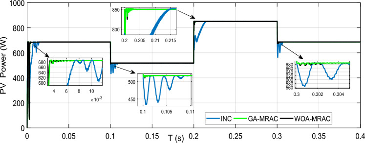
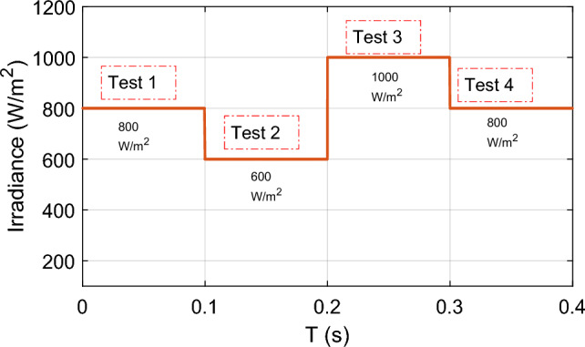
In this case, we consider the state of fast-changing irradiation levels, as shown in Fig. 16. We picked an irradiance profile with both step-up and step-down irradiation changes. In contrast, we set the temperature at the steady state, i.e., 25 °C. Figure 17 illustrates the PV power response for each technique used (GA-MRAC, WOA-MRAC, and INC). The MPPT performance depicted in Fig. 17 demonstrates that the settling time (TS) to reach MPP for the INC approach in the first test (Test 1) is 140 ms (ms). The GA-MRAC method takes 3.34 ms, while the WOA-MRAC method only requires 3.25 ms to reach MPP. The proposed optimal model reference adaptive controller (OMRAC) scheme exhibits superior dynamic performance using either GA or WOA. It quickly attains the MPP under irradiance variation and provides lower fluctuations around it throughout all four irradiation tests.
Figure 16.
Solar irradiance profile.
Figure 17.
PV array power under variable irradiance for three MPPT techniques.
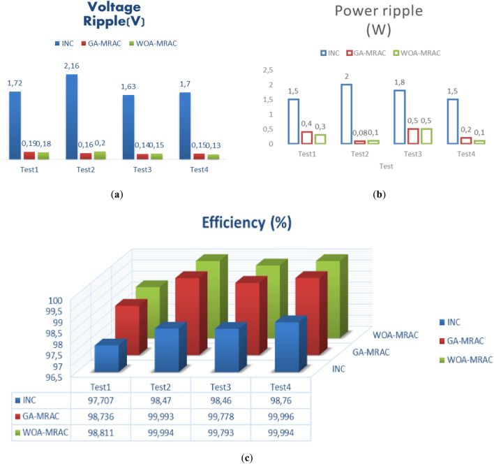
The proposed OMRAC method provides better power quality than the INC method regarding power ripple. The suggested controller managed to decrease the oscillation around the MPP, as shown in Fig. 18, as well as low voltage fluctuation with an average efficiency of 99.92% for GA-MRAC and 99.65% for WOA-MRAC. Table 4 summarizes the dynamic performance results for each irradiation level applied in detail. Figure 19 illustrates the graphical representation of voltage, power ripple, and tracking efficiency.
Figure 18.
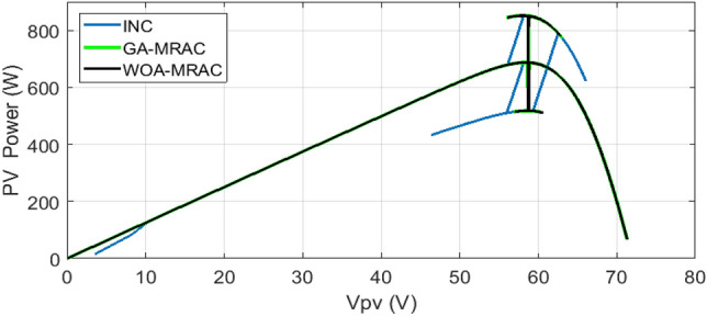
Power-Voltage characteristics under variable irradiation.
Table 4.
Analysis results for variable irradiation test.
| Test | MPPT | Settling times (ms) | Voltage ripple (V) | Power ripple (W) | Efficiency (%) | Error (IAE) | Error (ISE) |
|---|---|---|---|---|---|---|---|
| 1 | INC | 140 | 1.72 | 1.5 | 97.707 | 1.582 | 466.5 |
| GA-MRAC | 3.34 | 0.19 | 0.4 | 98.736 | 0.868 | 362.4 | |
| WOA-MRAC | 3.25 | 0.18 | 0.3 | 98.811 | 0.8165 | 341.6 | |
| INC | 63.77 | 2.16 | 2 | 98.47 | 0.2653 | 11.2 | |
| 2 | GA-MRAC | 0.547155 | 0.16 | 0.08 | 99.993 | 0.00576 | 0.04855 |
| WOA-MRAC | 0.547155 | 0.2 | 0.1 | 99.994 | 0.00491 | 0.04897 | |
| INC | 12.6914 | 1.63 | 1.8 | 98.46 | 1.32 | 157.3 | |
| 3 | GA-MRAC | 0.9169 | 0.14 | 0.5 | 99.778 | 0.1889 | 1.515 |
| WOA-MRAC | 0.9533 | 0.15 | 0.5 | 99.793 | 0.1764 | 1.383 | |
| INC | 6.2046 | 1.7 | 1.5 | 98.76 | 0.2629 | 16.49 | |
| 4 | GA-MRAC | 0.002589 | 0.15 | 0.2 | 99.996 | 0.00944 | 0.0618 |
| WOA-MRAC | 0.8416977 | 0.13 | 0.1 | 99.994 | 0.01712 | 0.1151 |
Figure 19.
Comparison evaluation using the graphical representation: (a) Voltage ripple, (b) Power ripple, (c) Tracking efficiency.
Under variable temperature and fixed irradiation
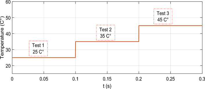
To carry out this case, the irradiation intensity was maintained at 1000 w/m2, while the temperature was manipulated by the temperature profile depicted in Fig. 20. A sudden shift of 10 °C was introduced to the temperature at each stage.
Figure 20.
Temperature profile.
Figure 21 shows the PV power output during a sudden temperature change using the proposed GA-MRAC and WOA-MRAC compared with the INC MPPT technique. It is worth mentioning that the suggested optimal MRAC exhibited significantly superior performance to INC. The traditional approach required 10.8 ms to monitor the maximum power point, whereas the GA-MRAC reaction time was calculated to be 1.8 ms. The WOA-MRAC MPPT converged in under 1.7 ms. Noteworthy, the OMRAC provides a superior improvement in convergence time under rapidly changing temperatures over all three temperature tests. The voltage Vpv generated by the photovoltaic (PV) array is depicted in Fig. 22; the optimal MRAC offers better VMPP tracking with a small voltage ripple. On the other hand, there is more voltage fluctuation around VMPP for the INC method.
Figure 21.
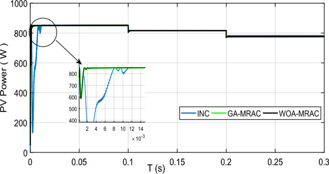
PV power output under variable temperature conditions.
Figure 22.
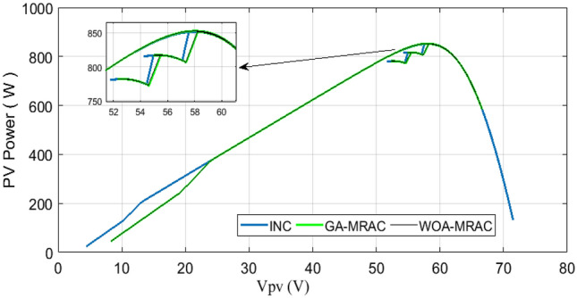
Power-Voltage curve under variable temperature.
Figure 23 shows the MPPT point tracking by three different algorithms. Accordingly, the suggested algorithm follows the MPP during varying temperature conditions with almost no power ripple.
Figure 23.
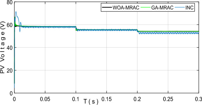
PV voltage output under variable temperature conditions.
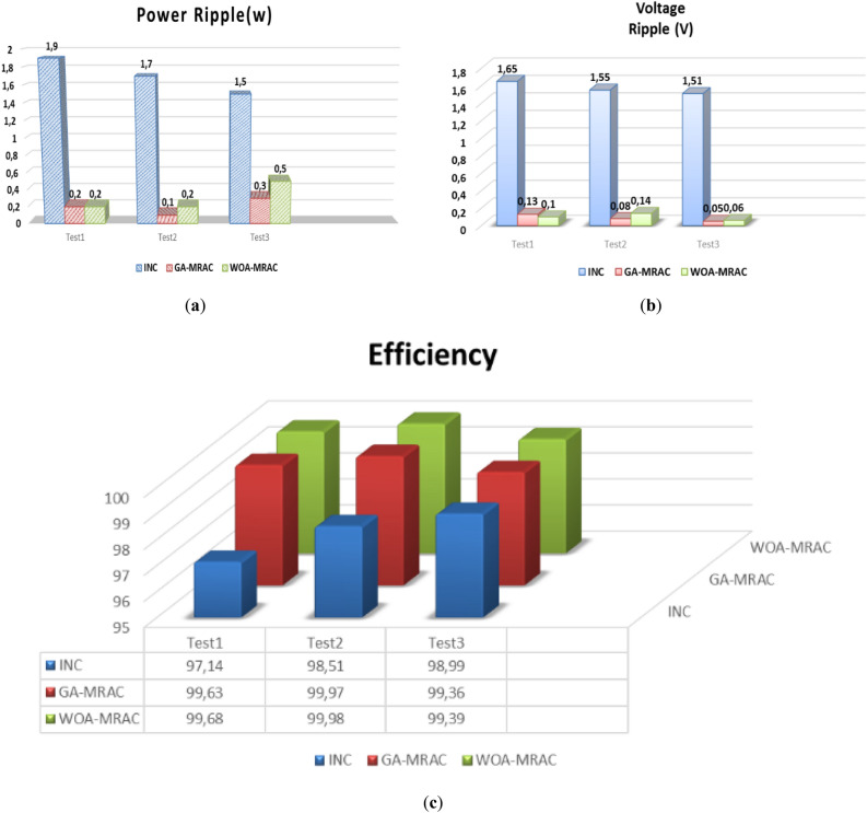
Table 5 shows a comparative analysis of the mentioned techniques under various temperature tests regarding settling time (Ts), Voltage ripple, power ripple, efficiency, IAE, and ISE. Addition to a graphical representation analysis to illustrate and support this comparative study is shown in Fig. 24. Through this table and graphic representation, we notice the superiority of WOA-MRAC, followed by GA-MRAC, and finally, the conventional INC technique. Table 6 thoroughly evaluates the most recent cutting-edge MPPT techniques.
Table 5.
Analysis results for variable temperature test.
| Test | MPPT | Settling times (ms) | Voltage ripple (V) | Power ripple (W) | Efficiency (%) | Error (IAE) | Error (ISE) |
|---|---|---|---|---|---|---|---|
| 1 | INC | 10.895 | 1.65 | 1.9 | 97.14 | 2.435 | 989.8 |
| GA-MRAC | 1.810545 | 0.13 | 0.2 | 99.63 | 0.3075 | 46.17 | |
| WOA-MRAC | 1.742495 | 0.1 | 0.2 | 99.68 | 0.2705 | 45.48 | |
| INC | 0.009627 | 1.55 | 1.7 | 98.51 | 0.04109 | 0.04575 | |
| 2 | GA-MRAC | 0.000792 | 0.08 | 0.1 | 99.97 | 0.01873 | 0.01618 |
| WOA-MRAC | 0.000799 | 0.14 | 0.2 | 99.98 | 0.0158 | 0.0196 | |
| INC | 0.0009611 | 1.51 | 1.5 | 98.99 | 0.04238 | 0.05594 | |
| 3 | GA-MRAC | 0.000877 | 0.05 | 0.3 | 99.36 | 0.495 | 2.462 |
| WOA-MRAC | 0.000891 | 0.06 | 0.5 | 99.39 | 0.474 | 2.258 | |
| INC | 10.895 | 1.65 | 1.9 | 97.14 | 2.435 | 989.8 | |
| 4 | GA-MRAC | 1.810545 | 0.13 | 0.2 | 99.63 | 0.3075 | 46.17 |
| WOA-MRAC | 1.742495 | 0.1 | 0.2 | 99.68 | 0.2705 | 45.48 |
Figure 24.
Comparison evaluation using the graphical representation under variable temperature: (a) Power ripple, (b) Voltage ripple, (c) Tracking efficiency.
Table 6.
Comparison of the several MPPT methods found in the literature.
| References | MPPT algorithms | Steady-state fluctuation | Tracking efficiency | Convergence | MPPT algorithms |
|---|---|---|---|---|---|
| 94 | Coarse and fine | Low | High | Low | Medium |
| 95 | IBA-FLC | Medium | High | Medium | High |
| 36 | ANN | Low | High | fast | Medium |
| 93 | Twisting Sliding Mode Control | Medium | Medium | fast | Low |
| 96 | Super twisting sliding mode-type two fuzzy | Low | Very high | fast | Low |
| 56 | P&O-MRAC | No | Very high | Very fast | Low |
| Proposed | ANFIS-WOA-MRAC | No | Very high | Very fast | medium |
Conclusions and future research directions
In this work, an innovative two-level maximum power point tracking (MPPT) controller designed for photovoltaic devices is developed. The first level of control includes the implementation of an Adaptive Neuro-Fuzzy (ANFIS) estimator to generate the voltage reference. To improve the MPPT algorithm efficiency even more, we introduced a second level of control using a model reference adaptive controller (MRAC). To optimize the MRAC controller performance, we employed two optimization techniques, Genetic Algorithm (GA) and Whale Optimization Algorithm (WOA), to fine-tune the controller's parameters. The proposed approach can cope with the challenges of quickly changing atmospheric conditions. The efficacy of the developed algorithm was verified through MATLAB/Simulink software. The performance of the innovative GA-MRAC and WOA-MRAC was compared with a conventional MPPT algorithm, namely incremental conductance (INC). Summing up the results, the WOA-MRAC controller exhibited the most excellent performance with the fastest convergence time, high tracking efficiency, and no further fluctuations. We conclude that the two-level MPPT control system shows promise for the optimization of PV systems, especially in dynamic environments where real-time tracking of the maximum power point is critical for energy harvesting.
In the future, several research directions could enhance the development of MPPT control systems for PV systems. Consider investigating alternative optimization algorithms other than genetic algorithms (GA) and whale optimization algorithms (WOA) to enhance the fine-tuning of MRAC parameters and maybe achieve superior outcomes. Evaluating the reliability of the two-level MPPT system in real-world scenarios, including partial shade, aging, and fluctuating load conditions, will offer vital insights into its practical use. Furthermore, combining the two-level MPPT system with additional control techniques like energy storage systems or grid-connected inverters could improve the system’s efficiency and reliability. Hardware prototypes and field tests are crucial for validating the performance of the two-level MPPT system in real-world situations, offering vital input for PV installations in both residential and commercial environments. Future study should prioritize optimizing and testing the two-level MPPT control system in real-world situations and investigating its integration with other control systems to improve performance.
Author contributions
N.D., A.B.: Conceptualization, Methodology, Software, Visualization, Investigation, Writing- Original draft preparation. F.M.: Data curation, Validation, Supervision, Resources, Writing—Review & Editing. M.B., I.Z.: Project administration, Supervision, Resources, Writing—Review & Editing.
Data availability
The datasets used and/or analysed during the current study available from the corresponding author on reasonable request.
Competing interests
The authors declare no competing interests.
Footnotes
Publisher's note
Springer Nature remains neutral with regard to jurisdictional claims in published maps and institutional affiliations.
Contributor Information
Abd Essalam Badoud, Email: badoudabde@univ-setif.dz.
Mohit Bajaj, Email: mohitbajaj.ee@geu.ac.in.
Ievgen Zaitsev, Email: zaitsev@i.ua.
References
- 1.Lyu, W. et al. Impact of battery electric vehicle usage on air quality in three Chinese first-tier cities. Sci. Rep.14, 21. 10.1038/s41598-023-50745-6 (2024). 10.1038/s41598-023-50745-6 [DOI] [PMC free article] [PubMed] [Google Scholar]
- 2.Li, P., Hu, J., Qiu, L., Zhao, Y. & Ghosh, B. K. A distributed economic dispatch strategy for power-water networks. IEEE Trans. Control Netw. Syst.9, 356–366. 10.1109/TCNS.2021.3104103 (2022). 10.1109/TCNS.2021.3104103 [DOI] [Google Scholar]
- 3.Duan, Y., Zhao, Y. & Hu, J. An initialization-free distributed algorithm for dynamic economic dispatch problems in microgrid: Modeling, optimization and analysis. Sustain Energy Grids Netw.34, 101004. 10.1016/j.segan.2023.101004 (2023). 10.1016/j.segan.2023.101004 [DOI] [Google Scholar]
- 4.Yan, C., Zou, Y., Wu, Z. & Maleki, A. Effect of various design configurations and operating conditions for optimization of a wind/solar/hydrogen/fuel cell hybrid microgrid system by a bio-inspired algorithm. Int. J. Hydrog. Energy60, 378–391. 10.1016/j.ijhydene.2024.02.004 (2024). 10.1016/j.ijhydene.2024.02.004 [DOI] [Google Scholar]
- 5.Yang, C. et al. Optimized integration of solar energy and liquefied natural gas regasification for sustainable urban development: Dynamic modeling, data-driven optimization, and case study. J. Clean Prod.447, 141405. 10.1016/j.jclepro.2024.141405 (2024). 10.1016/j.jclepro.2024.141405 [DOI] [Google Scholar]
- 6.Panda, S. et al. A comprehensive review on demand side management and market design for renewable energy support and integration. Energy Rep.10, 2228–2250. 10.1016/j.egyr.2023.09.049 (2023). 10.1016/j.egyr.2023.09.049 [DOI] [Google Scholar]
- 7.Sahoo, G. K., Choudhury, S., Rathore, R. S., Bajaj, M. & Dutta, A. K. Scaled conjugate-artificial neural network-based novel framework for enhancing the power quality of grid-tied microgrid systems. Alex. Eng. J.80, 520–541. 10.1016/j.aej.2023.08.081 (2023). 10.1016/j.aej.2023.08.081 [DOI] [Google Scholar]
- 8.Mao, M. et al. Classification and summarization of solar photovoltaic MPPT techniques: A review based on traditional and intelligent control strategies. Energy Rep.6, 1312–1327. 10.1016/j.egyr.2020.05.013 (2020). 10.1016/j.egyr.2020.05.013 [DOI] [Google Scholar]
- 9.Kiran, S. R., Murali, M., Hussaian Basha, C. & Fathima, F. Design of artificial intelligence-based hybrid MPPT controllers for partially shaded solar PV system with non-isolated boost converter. Comput. Vis. Robot.13, 353–363. 10.1007/978-981-16-8225-4_28 (2022). 10.1007/978-981-16-8225-4_28 [DOI] [Google Scholar]
- 10.Shirkhani, M. et al. A review on microgrid decentralized energy/voltage control structures and methods. Energy Rep.10, 368–380. 10.1016/j.egyr.2023.06.022 (2023). 10.1016/j.egyr.2023.06.022 [DOI] [Google Scholar]
- 11.Hussaian Basha, C. et al. Design of GWO based fuzzy MPPT controller for fuel cell fed EV application with high voltage gain DC-DC converter. Mater. Today Proc.92, 66–72. 10.1016/j.matpr.2023.03.727 (2023). 10.1016/j.matpr.2023.03.727 [DOI] [Google Scholar]
- 12.Mohammadi, E., Alizadeh, M., Asgarimoghaddam, M., Wang, X. & Simoes, M. G. A review on application of artificial intelligence techniques in microgrids. IEEE J. Emerg. Sel. Top. Ind. Electron.3, 878–890. 10.1109/JESTIE.2022.3198504 (2022). 10.1109/JESTIE.2022.3198504 [DOI] [Google Scholar]
- 13.Badoud, A. E. MPPT controller for PV array under partially shaded condition. Alger. J. Renew. Energy Sustain. Dev.01, 99–111. 10.46657/ajresd.2019.1.1.10 (2019). 10.46657/ajresd.2019.1.1.10 [DOI] [Google Scholar]
- 14.Badoud, A. E. Real-time experimental analysis of hybrid BG-FL based MPPT controller for a photovoltaic system under partial shading conditions. In 2022 19th Int. Multi-Conference Syst. Signals Devices, IEEE; pp. 1409–14 (2022). 10.1109/SSD54932.2022.9955848
- 15.Hussaian Basha, C. H., Naresh, T., Amaresh, K., Preethi Raj, P. M. & Akram, P. Design and performance analysis of common duty ratio controlled zeta converter with an adaptive P&O MPPT controller. Proc. Int. Conf. Data Sci. Appl.42, 657–671. 10.1007/978-981-16-5120-5_50 (2022). 10.1007/978-981-16-5120-5_50 [DOI] [Google Scholar]
- 16.Farh, H. M. H., Fathy, A., Al-Shamma’a, A. A., Mekhilef, S. & Al-Shaalan, A. M. Global research trends on photovoltaic maximum power extraction: Systematic and scientometric analysis. Sustain. Energy Technol. Assess.61, 103585. 10.1016/j.seta.2023.103585 (2024). 10.1016/j.seta.2023.103585 [DOI] [Google Scholar]
- 17.Rafikiran, S. et al. Design and performance analysis of hybrid MPPT controllers for fuel cell fed DC–DC converter systems. Energy Rep.9, 5826–5842. 10.1016/j.egyr.2023.05.030 (2023). 10.1016/j.egyr.2023.05.030 [DOI] [Google Scholar]
- 18.Dadkhah, J. & Niroomand, M. Optimization methods of MPPT parameters for PV systems: Review, classification, and comparison. J. Mod. Power Syst. Clean Energy9, 225–236. 10.35833/MPCE.2019.000379 (2021). 10.35833/MPCE.2019.000379 [DOI] [Google Scholar]
- 19.Murali, M., Basha, C. H., Kiran, S. R. & Amaresh, K. Design and analysis of neural network-based MPPT technique for solar power-based electric vehicle application. In Proc. Fourth Int. Conf. Inven. Mater. Sci. Appl., 150, pp. 529–41 (2022). 10.1007/978-981-16-4321-7_44
- 20.Abderrahim, Z., Eddine, H. K. & Sabir, M. A new improved variable step size MPPT method for photovoltaic systems using grey wolf and whale optimization technique based PID controller. J. Eur. Des. Systèmes Autom.54, 175–185. 10.18280/jesa.540120 (2021). 10.18280/jesa.540120 [DOI] [Google Scholar]
- 21.Basha, C. H. H. & Rani, C. A new single switch DC-DC converter for PEM fuel cell-based electric vehicle system with an improved beta-fuzzy logic MPPT controller. Soft Comput.26, 6021–6040. 10.1007/s00500-022-07049-0 (2022). 10.1007/s00500-022-07049-0 [DOI] [Google Scholar]
- 22.Khadidja, S., Mountassar, M. & Mhamed, B. Comparative study of incremental conductance and perturb & observe MPPT methods for photovoltaic system. In 2017 Int. Conf. Green Energy Convers. Syst., IEEE, pp. 1–6 (2017). 10.1109/GECS.2017.8066230
- 23.Alsumiri, M. Residual incremental conductance based nonparametric MPPT control for solar photovoltaic energy conversion system. IEEE Access7, 87901–87906. 10.1109/ACCESS.2019.2925687 (2019). 10.1109/ACCESS.2019.2925687 [DOI] [Google Scholar]
- 24.Hussaian Basha, C., Rani, C., Brisilla, R. M. & Odofin, S. Simulation of metaheuristic intelligence MPPT techniques for solar PV under partial shading condition. Soft Comput. Probl. Solving46, 773–785. 10.1007/978-981-15-0035-0_63 (2020). 10.1007/978-981-15-0035-0_63 [DOI] [Google Scholar]
- 25.Basha, C. H. & Rani, C. Design and analysis of transformerless, high step-up, boost DC–DC converter with an improved VSS-RBFA based MPPT controller. Int. Trans. Electr. Energy Syst.30, 1041–1044. 10.1002/2050-7038.12633 (2020). 10.1002/2050-7038.12633 [DOI] [Google Scholar]
- 26.Fangrui, L., Yong, K., Yu, Z., Shanxu, D. Comparison of P&O and hill climbing MPPT methods for grid-connected PV converter. In 2008 3rd IEEE Conf. Ind. Electron. Appl., IEEE, pp. 804–7 (2008). 10.1109/ICIEA.2008.4582626
- 27.Govinda Chowdary, V., Udhay Sankar, V., Mathew, D., Hussaian Basha, C. & Rani, C. Hybrid fuzzy logic-based MPPT for wind energy conversion system. Soft Comput. Probl. Solving150, 951–968. 10.1007/978-981-15-0184-5_81 (2020). 10.1007/978-981-15-0184-5_81 [DOI] [Google Scholar]
- 28.Wang, Y., Jiang, X., Xie, X., Yang, X. & Xiao, X. Identifying sources of subsynchronous resonance using wide-area phasor measurements. IEEE Trans. Power Deliv.36, 3242–3254. 10.1109/TPWRD.2020.3037289 (2021). 10.1109/TPWRD.2020.3037289 [DOI] [Google Scholar]
- 29.Wang, H. et al. A junction temperature monitoring method for IGBT modules based on turn-off voltage with convolutional neural networks. IEEE Trans. Power Electron.38, 10313–10328. 10.1109/TPEL.2023.3278675 (2023). 10.1109/TPEL.2023.3278675 [DOI] [Google Scholar]
- 30.Killi, M. & Samanta, S. Modified perturb and observe MPPT algorithm for drift avoidance in photovoltaic systems. IEEE Trans. Ind. Electron.62, 5549–5559. 10.1109/TIE.2015.2407854 (2015). 10.1109/TIE.2015.2407854 [DOI] [Google Scholar]
- 31.Shang, L., Guo, H. & Zhu, W. An improved MPPT control strategy based on incremental conductance algorithm. Prot. Control Mod. Power Syst.5, 14. 10.1186/s41601-020-00161-z (2020). 10.1186/s41601-020-00161-z [DOI] [Google Scholar]
- 32.Abo-Khalil, A. G., El-Sharkawy, I. I., Radwan, A. & Memon, S. Influence of a hybrid MPPT technique, SA-P&O, on PV system performance under partial shading conditions. Energies16, 577. 10.3390/en16020577 (2023). 10.3390/en16020577 [DOI] [Google Scholar]
- 33.Bollipo, R. B., Mikkili, S. & Bonthagorla, P. K. Critical review on PV MPPT techniques: Classical, intelligent and optimisation. IET Renew. Power Gener.14, 1433–1452. 10.1049/iet-rpg.2019.1163 (2020). 10.1049/iet-rpg.2019.1163 [DOI] [Google Scholar]
- 34.Yilmaz, U., Kircay, A. & Borekci, S. PV system fuzzy logic MPPT method and PI control as a charge controller. Renew. Sustain. Energy Rev.81, 994–1001. 10.1016/j.rser.2017.08.048 (2018). 10.1016/j.rser.2017.08.048 [DOI] [Google Scholar]
- 35.Basha, C. H. & Rani, C. Design and analysis of transformerless, high step-up, boost DC–DC converter with an improved VSS-RBFA based MPPT controller. Int. Trans. Electr. Energy Syst.30, 2036. 10.1002/2050-7038.12633 (2020). 10.1002/2050-7038.12633 [DOI] [Google Scholar]
- 36.Bouselham, L., Hajji, M., Hajji, B. & Bouali, H. A new MPPT-based ANN for photovoltaic system under partial shading conditions. Energy Procedia111, 924–933. 10.1016/j.egypro.2017.03.255 (2017). 10.1016/j.egypro.2017.03.255 [DOI] [Google Scholar]
- 37.Hussaian Basha, C., Bansal, V., Rani, C., Brisilla, R. M. & Odofin, S. Development of cuckoo search MPPT algorithm for partially shaded solar PV SEPIC converter. Soft Comput. Probl. Solving12, 727–736. 10.1007/978-981-15-0035-0_59 (2020). 10.1007/978-981-15-0035-0_59 [DOI] [Google Scholar]
- 38.Kiran, S. R. et al. Reduced simulative performance analysis of variable step size ANN based MPPT techniques for partially shaded solar PV systems. IEEE Access10, 48875–48889. 10.1109/ACCESS.2022.3172322 (2022). 10.1109/ACCESS.2022.3172322 [DOI] [Google Scholar]
- 39.Ali, K. et al. Robust integral backstepping based nonlinear MPPT control for a PV system. Energies12, 3180. 10.3390/en12163180 (2019). 10.3390/en12163180 [DOI] [Google Scholar]
- 40.Ahmad, F. F., Ghenai, C., Hamid, A. K. & Bettayeb, M. Application of sliding mode control for maximum power point tracking of solar photovoltaic systems: A comprehensive review. Annu. Rev. Control49, 173–196. 10.1016/j.arcontrol.2020.04.011 (2020). 10.1016/j.arcontrol.2020.04.011 [DOI] [Google Scholar]
- 41.Bouguerra, A., Badoud, A. E., Mekheilef, S. & Chouder, A. Comparative study of perturb and observe incremental conductance and particle swarm optimisation for maximum power point tracking under changing irradiance. In 2023 2nd Int. Conf. Electron. Energy Meas., IEEE, pp. 1–7 (2023). 10.1109/IC2EM59347.2023.10419737
- 42.Hadji, S., Gaubert, J.-P. & Krim, F. Real-time genetic algorithms-based MPPT: Study and comparison (theoretical an experimental) with conventional methods. Energies11, 459. 10.3390/en11020459 (2018). 10.3390/en11020459 [DOI] [Google Scholar]
- 43.Guo, M. W., Wang, J. S., Zhu, L. F., Guo, S. S. & Xie, W. An improved grey wolf optimizer based on tracking and seeking modes to solve function optimization problems. IEEE Access8, 69861–69893. 10.1109/ACCESS.2020.2984321 (2020). 10.1109/ACCESS.2020.2984321 [DOI] [Google Scholar]
- 44.Ebrahim, M. A., Osama, A., Kotb, K. M. & Bendary, F. Whale inspired algorithm based MPPT controllers for grid-connected solar photovoltaic system. Energy Procedia162, 77–86. 10.1016/j.egypro.2019.04.009 (2019). 10.1016/j.egypro.2019.04.009 [DOI] [Google Scholar]
- 45.Badoud, A. E., Ayat, Y. & Mekhilef, S. Development and experimental validation of novel robust MPPT controller based on bond graph and fuzzy logic for PV system under variable weather conditions. Int. Trans. Electr. Energy Syst.10.1002/2050-7038.13091 (2021). 10.1002/2050-7038.13091 [DOI] [Google Scholar]
- 46.Xiao, Y., Zhao, Y., Shen, Z. & Jiao, H. SMGSA algorithm-based MPPT control strategy. J. Power Electron.10.1007/s43236-023-00757-2 (2024). 10.1007/s43236-023-00757-2 [DOI] [Google Scholar]
- 47.Mohanty, S. et al. Demand side management of electric vehicles in smart grids: A survey on strategies, challenges, modeling, and optimization. Energy Rep.8, 12466–12490. 10.1016/j.egyr.2022.09.023 (2022). 10.1016/j.egyr.2022.09.023 [DOI] [Google Scholar]
- 48.Panda, S. et al. Residential demand side management model, optimization and future perspective: A review. Energy Rep.8, 3727–3766. 10.1016/j.egyr.2022.02.300 (2022). 10.1016/j.egyr.2022.02.300 [DOI] [Google Scholar]
- 49.Arsalan, M. et al. MPPT for photovoltaic system using nonlinear backstepping controller with integral action. Sol. Energy170, 192–200. 10.1016/j.solener.2018.04.061 (2018). 10.1016/j.solener.2018.04.061 [DOI] [Google Scholar]
- 50.Harrag, A. & Messalti, S. Variable step size modified P&O MPPT algorithm using GA-based hybrid offline/online PID controller. Renew. Sustain. Energy Rev.49, 1247–1260. 10.1016/j.rser.2015.05.003 (2015). 10.1016/j.rser.2015.05.003 [DOI] [Google Scholar]
- 51.Jalali Zand, S. et al. Optimized fuzzy controller based on cuckoo optimization algorithm for maximum power-point tracking of photovoltaic systems. IEEE Access10, 71699–71716. 10.1109/ACCESS.2022.3184815 (2022). 10.1109/ACCESS.2022.3184815 [DOI] [Google Scholar]
- 52.Ammar, H. H., Azar, A. T., Mahmoud, M. I. & Shalaby, R. Evaluation of the performance of a FONN-based MPPT control for a photovoltaic watering system. Ain Shams Eng. J.15, 102329. 10.1016/j.asej.2023.102329 (2024). 10.1016/j.asej.2023.102329 [DOI] [Google Scholar]
- 53.Hussaian Basha, C. H. & Rani, C. Performance analysis of MPPT techniques for dynamic irradiation condition of solar PV. Int. J. Fuzzy Syst.22, 2577–2598. 10.1007/s40815-020-00974-y (2020). 10.1007/s40815-020-00974-y [DOI] [Google Scholar]
- 54.Khanna, R., Qinhao, Z., Stanchina, W. E., Reed, G. F. & Zhi-Hong, M. Maximum power point tracking using model reference adaptive control. IEEE Trans. Power Electron.29, 1490–1499. 10.1109/TPEL.2013.2263154 (2014). 10.1109/TPEL.2013.2263154 [DOI] [Google Scholar]
- 55.Tariba, N., Haddou, A., El Omari, H. & El Omari, H. Design and implementation an adaptive control for MPPT systems using model reference adaptive controller. In 2016 Int. Renew. Sustain. Energy Conf., IEEE, pp. 165–72 (2016). 10.1109/IRSEC.2016.7984021
- 56.Manna, S. et al. Design and implementation of a new adaptive MPPT controller for solar PV systems. Energy Rep.9, 1818–1829. 10.1016/j.egyr.2022.12.152 (2023). 10.1016/j.egyr.2022.12.152 [DOI] [Google Scholar]
- 57.Basha, C. H. & Rani, C. Different conventional and soft computing MPPT techniques for solar PV systems with high step-up boost converters: A comprehensive analysis. Energies13, 371. 10.3390/en13020371 (2020). 10.3390/en13020371 [DOI] [Google Scholar]
- 58.Pankaj, S. & Shailendra, J. R. N. Effect of adaptation gain on system performance for model reference adaptive control scheme using MIT rule. Int. J. Electr. Comput. Eng.4, 1547–1552 (2010). [Google Scholar]
- 59.Mirjalili, S. & Lewis, A. The whale optimization algorithm. Adv. Eng. Softw.95, 51–67. 10.1016/j.advengsoft.2016.01.008 (2016). 10.1016/j.advengsoft.2016.01.008 [DOI] [Google Scholar]
- 60.Dadkhah Tehrani, R. & Shabaninia, F. Two-level control of photovoltaic systems using global perturbation-based extremum seeking control and model reference adaptive control. Trans. Inst. Meas. Control40, 3709–3720. 10.1177/0142331217731620 (2018). 10.1177/0142331217731620 [DOI] [Google Scholar]
- 61.Wang, H., Sun, W., Jiang, D. & Qu, R. A MTPA and flux-weakening curve identification method based on physics-informed network without calibration. IEEE Trans. Power Electron.38, 12370–12375. 10.1109/TPEL.2023.3295913 (2023). 10.1109/TPEL.2023.3295913 [DOI] [Google Scholar]
- 62.Hu, F. et al. Research on the evolution of China’s photovoltaic technology innovation network from the perspective of patents. Energy Strateg. Rev.51, 101309. 10.1016/j.esr.2024.101309 (2024). 10.1016/j.esr.2024.101309 [DOI] [Google Scholar]
- 63.Tamalouzt, S. et al. Enhanced direct reactive power control-based multi-level inverter for DFIG wind system under variable speeds. Sustainability13, 9060. 10.3390/su13169060 (2021). 10.3390/su13169060 [DOI] [Google Scholar]
- 64.Choudhury, S., Bajaj, M., Dash, T., Kamel, S. & Jurado, F. Multilevel inverter: A survey on classical and advanced topologies, control schemes, applications to power system and future prospects. Energies14, 5773. 10.3390/en14185773 (2021). 10.3390/en14185773 [DOI] [Google Scholar]
- 65.Mohapatra, B. et al. Optimizing grid-connected PV systems with novel super-twisting sliding mode controllers for real-time power management. Sci. Rep.14, 4646. 10.1038/s41598-024-55380-3 (2024). 10.1038/s41598-024-55380-3 [DOI] [PMC free article] [PubMed] [Google Scholar]
- 66.Liu, G. Data collection in MI-assisted wireless powered underground sensor networks: Directions, recent advances, and challenges. IEEE Commun. Mag.59, 132–138. 10.1109/MCOM.001.2000921 (2021). 10.1109/MCOM.001.2000921 [DOI] [Google Scholar]
- 67.Hou, M., Zhao, Y. & Ge, X. Optimal scheduling of the plug-in electric vehicles aggregator energy and regulation services based on grid to vehicle. Int. Trans. Electr. Energy Syst.27, e2364. 10.1002/etep.2364 (2017). 10.1002/etep.2364 [DOI] [Google Scholar]
- 68.Mohapatra, B. et al. Real-time validation of a novel IAOA technique-based offset hysteresis band current controller for grid-tied photovoltaic system. Energies15, 8790. 10.3390/en15238790 (2022). 10.3390/en15238790 [DOI] [Google Scholar]
- 69.Choudhury, S. et al. Energy management and power quality improvement of microgrid system through modified water wave optimization. Energy Rep.9, 6020–6041. 10.1016/j.egyr.2023.05.068 (2023). 10.1016/j.egyr.2023.05.068 [DOI] [Google Scholar]
- 70.Rekioua, D. et al. Optimization and intelligent power management control for an autonomous hybrid wind turbine photovoltaic diesel generator with batteries. Sci. Rep.13, 21830. 10.1038/s41598-023-49067-4 (2023). 10.1038/s41598-023-49067-4 [DOI] [PMC free article] [PubMed] [Google Scholar]
- 71.Manna, S., Akella, A. K. & Singh, D. K. A novel MRAC-MPPT scheme to enhance speed and accuracy in PV systems. Iran J. Sci. Technol. Trans. Electr. Eng.47, 233–254. 10.1007/s40998-022-00542-0 (2023). 10.1007/s40998-022-00542-0 [DOI] [Google Scholar]
- 72.Manna, S., Akella, A. K. & Singh, D. K. Novel Lyapunov-based rapid and ripple-free MPPT using a robust model reference adaptive controller for solar PV system. Prot. Control Mod. Power Syst.8, 13. 10.1186/s41601-023-00288-9 (2023). 10.1186/s41601-023-00288-9 [DOI] [Google Scholar]
- 73.Naghmash, et al. Backstepping based non-linear control for maximum power point tracking in photovoltaic system. Sol. Energy159, 134–141. 10.1016/j.solener.2017.10.062 (2018). 10.1016/j.solener.2017.10.062 [DOI] [Google Scholar]
- 74.Azaroual, M. et al. Optimal solution of peer-to-peer and peer-to-grid trading strategy sharing between prosumers with grid-connected photovoltaic/wind turbine/battery storage systems. Int. J. Energy Res.2023, 1–17. 10.1155/2023/6747936 (2023). 10.1155/2023/6747936 [DOI] [Google Scholar]
- 75.Sivapriya, A. et al. Real-time hardware-in-loop based open circuit fault diagnosis and fault tolerant control approach for cascaded multilevel inverter using artificial neural network. Front. Energy Res.10.3389/fenrg.2022.1083662 (2023). 10.3389/fenrg.2022.1083662 [DOI] [Google Scholar]
- 76.Pasik-Duncan, B. Adaptive control. IEEE Control Syst.16, 87. 10.1109/MCS.1996.487415 (1996). 10.1109/MCS.1996.487415 [DOI] [Google Scholar]
- 77.Lei, Y., Yanrong, C., Hai, T., Ren, G. & Wenhuan, W. DGNet: An adaptive lightweight defect detection model for new energy vehicle battery current collector. IEEE Sens. J.23, 29815–29830. 10.1109/JSEN.2023.3324441 (2023). 10.1109/JSEN.2023.3324441 [DOI] [Google Scholar]
- 78.Li, S., Zhao, X., Liang, W., Hossain, M. T. & Zhang, Z. A fast and accurate calculation method of line breaking power flow based on Taylor expansion. Front. Energy Res.10.3389/fenrg.2022.943946 (2022). 10.3389/fenrg.2022.943946 [DOI] [Google Scholar]
- 79.Mirjalili, S. Evolutionary Algorithms and Neural Networks Vol. 780 (Springer, 2019). 10.1007/978-3-319-93025-1. [Google Scholar]
- 80.Lu, Y., Tan, C., Ge, W., Zhao, Y. & Wang, G. Adaptive disturbance observer-based improved super-twisting sliding mode control for electromagnetic direct-drive pump. Smart Mater. Struct.32, 017001. 10.1088/1361-665X/aca84e (2023). 10.1088/1361-665X/aca84e [DOI] [Google Scholar]
- 81.Sun, R., Dai, Y. & Cheng, Q. An adaptive weighting strategy for multisensor integrated navigation in urban areas. IEEE Internet Things J.10, 12777–12786. 10.1109/JIOT.2023.3256008 (2023). 10.1109/JIOT.2023.3256008 [DOI] [Google Scholar]
- 82.Hamed, S. B. et al. A robust MPPT approach based on first-order sliding mode for triple-junction photovoltaic power system supplying electric vehicle. Energy Rep.9, 4275–4297. 10.1016/j.egyr.2023.02.086 (2023). 10.1016/j.egyr.2023.02.086 [DOI] [Google Scholar]
- 83.Kalaiarasi, N. et al. Performance evaluation of various Z-source inverter topologies for PV applications using AI-based MPPT techniques. Int. Trans. Electr. Energy Syst.2023, 1–16. 10.1155/2023/1134633 (2023). 10.1155/2023/1134633 [DOI] [Google Scholar]
- 84.Yang, M. et al. Digital twin-driven industrialization development of underwater gliders. IEEE Trans. Ind. Inform.19, 9680–9690. 10.1109/TII.2023.3233972 (2023). 10.1109/TII.2023.3233972 [DOI] [Google Scholar]
- 85.Li, R. et al. Mechanical safety prediction of a battery-pack system under low speed frontal impact via machine learning. Eng. Anal. Bound. Elem.160, 65–75. 10.1016/j.enganabound.2023.12.031 (2024). 10.1016/j.enganabound.2023.12.031 [DOI] [Google Scholar]
- 86.Tran, T.-S. & Kieu, T.-T.-H. Choice of selection methods in genetic algorithms for power system state estimation. Adv. Eng. Res. Appl.10.1007/978-3-030-64719-3_26 (2021). 10.1007/978-3-030-64719-3_26 [DOI] [Google Scholar]
- 87.Yu, J., Dong, X., Li, Q., Lu, J. & Ren, Z. Adaptive practical optimal time-varying formation tracking control for disturbed high-order multi-agent systems. IEEE Trans. Circuits Syst. I Regul. Pap.69, 2567–2578. 10.1109/TCSI.2022.3151464 (2022). 10.1109/TCSI.2022.3151464 [DOI] [Google Scholar]
- 88.Xu, B., Wang, X., Zhang, J., Guo, Y. & Razzaqi, A. A. A novel adaptive filtering for cooperative localization under compass failure and non-Gaussian noise. IEEE Trans. Veh. Technol.71, 3737–3749. 10.1109/TVT.2022.3145095 (2022). 10.1109/TVT.2022.3145095 [DOI] [Google Scholar]
- 89.Mfetoum, I. M. et al. A multilayer perceptron neural network approach for optimizing solar irradiance forecasting in Central Africa with meteorological insights. Sci. Rep.14, 3572. 10.1038/s41598-024-54181-y (2024). 10.1038/s41598-024-54181-y [DOI] [PMC free article] [PubMed] [Google Scholar]
- 90.Naoussi, S. R. D. et al. Enhancing MPPT performance for partially shaded photovoltaic arrays through backstepping control with Genetic Algorithm-optimized gains. Sci. Rep.14, 3334. 10.1038/s41598-024-53721-w (2024). 10.1038/s41598-024-53721-w [DOI] [PMC free article] [PubMed] [Google Scholar] [Retracted]
- 91.Mosaad, A. M., Attia, M. A. & Abdelaziz, A. Y. Whale optimization algorithm to tune PID and PIDA controllers on AVR system. Ain Shams Eng. J.10, 755–767. 10.1016/j.asej.2019.07.004 (2019). 10.1016/j.asej.2019.07.004 [DOI] [Google Scholar]
- 92.Gharehchopogh, F. S. & Gholizadeh, H. A comprehensive survey: Whale optimization algorithm and its applications. Swarm Evol. Comput.48, 1–24. 10.1016/j.swevo.2019.03.004 (2019). 10.1016/j.swevo.2019.03.004 [DOI] [Google Scholar]
- 93.Kayişli, K. & Caglayan, R. Z. Twisting sliding mode control based maximum power point tracking. Balk. J. Electr. Comput. Eng.10, 356–362. 10.17694/bajece.1137170 (2022). 10.17694/bajece.1137170 [DOI] [Google Scholar]
- 94.Kavya, M. & Jayalalitha, S. A novel coarse and fine control algorithm to improve maximum power point tracking (MPPT) efficiency in photovoltaic system. ISA Trans.121, 180–190. 10.1016/j.isatra.2021.03.036 (2022). 10.1016/j.isatra.2021.03.036 [DOI] [PubMed] [Google Scholar]
- 95.Ali, Z. M. et al. Novel hybrid improved bat algorithm and fuzzy system based MPPT for photovoltaic under variable atmospheric conditions. Sustain. Energy Technol. Assess.52, 102156. 10.1016/j.seta.2022.102156 (2022). 10.1016/j.seta.2022.102156 [DOI] [Google Scholar]
- 96.Kayisli, K. Super twisting sliding mode-type 2 fuzzy MPPT control of solar PV system with parameter optimization under variable irradiance conditions. Ain Shams Eng. J.14, 101950. 10.1016/j.asej.2022.101950 (2023). 10.1016/j.asej.2022.101950 [DOI] [Google Scholar]
Associated Data
This section collects any data citations, data availability statements, or supplementary materials included in this article.
Data Availability Statement
The datasets used and/or analysed during the current study available from the corresponding author on reasonable request.


