

Abstract
Descend and ascend of deep-water human-occupied submersibles based on buoyancy changes are enabled using a denomination of dispensable drop-weights, and loss of buoyancy are managed using emergency drop-weights and jettisoning identified systems. Failing to release the drop weights or jettison results in submersible stranding on the sea floor, leads to emergency recovery, and hence the drop-weight configuration has to be highly reliable. The paper, for the first time, based on hydrostatic stability, descend/ascend velocity needs, ocean salinity profile and loss-of-buoyancy situations, proposes a novel on-demand reliability based methodology for determining the safe drop-weight configuration and degradation-based mission abort strategy for deep-ocean human submersibles. Probabilistic on-demand reliability analysis based on IEC61508 standards for safety–critical systems using component field-failure data is carried out and the drop-weight configuration essential to meet the human-rated safety integrity level 3 during all stages of the subsea mission is identified for the deep-ocean human scientific submersible Matsya6000, based on which a mission abort protocol is evolved.
Keywords: Drop-weights, Reliability, Safety, Submersible, Mission abort policy
Subject terms: Ocean sciences, Engineering, Mathematics and computing
Introduction
Human occupied vehicles (HOVs) have the advantages of taking scientists to deep-ocean for carrying out high-resolution bathymetry, geological surveys, search activities, salvage operations, biological sampling, habitat analysis and carry out in-situ experiments. Scientists can continuously obtain real-time and in-situ data, design experiments and perform fine operations based on actual dynamics in real-time compared to remotely operated (ROVs) and unmanned robotic vehicles (AUVs) and systems.Subsequent to the 1st generation bathyscaphe Trieste in which which Jacques Piccard and Don Walsh descended up to 10.9 km reaching the Challenger Deep, the lowest point of Mariana Trench in 1960, the 2nd generation scientific HOVs (Alvin, Nautile,Shinkai, MIR, RUS, Consul and Jiaolong) developed during 1960–2010 featured lighter pressure-resistant hull for the crew, improved power supply for propulsion, and establishment of reliable subsystems that greatly expanded the operating range and efficiency1.The 3rd generation hadal depth HOVs developed during 2012–2023 (Deep Sea Challenger, Triton, Fendouzhe) pushed the technological boundaries to unprecedented levels2 .
Development of Matsya6000
The battery-powered HOV Matsya6000 (Fig. 1), indigenously developed by India’s Ministry of Earth Sciences- National Institute of Ocean Technology (MoES-NIOT) shall carry 3 persons up to 6000 m water depth for an operating period of 12 h, and supports 96 h of emergency3. The major subsystems of Matsya6000 include Titanium-alloy personnel sphere for accommodating three persons, Titanium-alloy exo-structure, syntactic foam for fixed buoyancy, main ballast system for enabling diving, variable ballast system for fine changes in buoyancy, drop-weights for energy-efficient descend/ascend and emergency, redundant power and control architecture, electric thrusters for propulsion, navigation and positioning systems, voice communication and data telemetry, and manipulators for sampling operations (Fig. 1). The 4th generation Matsya6000 focuses on increased human safety and reliable performance has ten distinct features including SIL3 rated emergency ballast drop-weight system, submersible on-board/ship-based digital-twin assistance for safety–critical operations, real-time monitoring of crew and submersible health from the deployment ship, fully-redundant power, control, positioning and communication architecture, on-board pressure-balanced lithium-polymer batteries, ultra-high definition color cameras, novel vehicle emergency rescue system and sub-sea surface parking capability.
Figure 1.
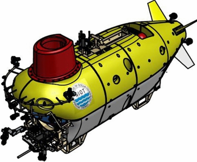
Model of Matsya6000 HOV.
System engineering approach based on IEC15288 standards is adopted for the development of Matsya6000. The realization approach includes definition of Concept of Operations (ConOps), optimized general arrangement, hydrostatic stability (weight/buoyancy calculations and free-board determination), hydrodynamic drag determination for propulsion power estimation and redundancy definition through Failure Mode Effect and Criticality Analysis (FMECA). The DNV’s Underwater Technology rules for manned submersible are followed for ensuring human-rated design4. For human safety–critical systems, on-demand reliability IEC 61,508/Safety Integrity Level (SIL)/ALARP is adopted, while for other mission-critical subsystems, redundancy is defined based on the principles of as low as reasonably achievable (ALARA) computed based on probabilistic reliability analysis(PRA) with DNV-OREDA field failure data as inputs5 . Detailed system engineering is completed and procurement of subsystems is near completion. Integration of the subsystems on the exo-structure is in progress.
Need for on-demand reliability assessment for drop-weight system and mission abort protocol
A reliable and energy-efficient descend-ascend system (DAS) is the key requirement to ensure safety of the crew and the submersible, as well as to increase the availability of battery energy (limited by vehicle weight and volume constraints) for the subsea mission. Deep-ocean submersible descend and ascend could be enabled by propulsion thrusters, pump-based variable buoyancy (VB) system and/or dispensable drop weights. Trade-off studies carried out between thruster-enabled and VB-based configurations on WHOI RHOV indicate that thruster-enabled descend/ascend up to 6500 m water depth with 30º vehicle pitch results in an energy consumption of ~ 10kWh, compared to zero pitch which could result in ~ 20kWh and VB system that could consume 8kWh6. It is also reported that, under continuous operation, with the present technological maturity, the probability of failure (PoF) of thruster-enabled descend/ascend system in 1 year is ~ 94%, a corresponding MTBF of 0.35 years7. Thus, compared to thruster and VB-based DAS, drop-weight based system shall be energy-efficient.
Failures of the DAS during descend leads to submersible hitting the ocean floor and its failure during ascend leads to submersible stranding on the ocean floor. Retrieval of the deep-ocean stranded submersible within 96 h requires mammoth effort, and hence DAS needs to be extremely reliable for human-rated application. Hence, a methodology for evaluating the on-demand reliability (ODR) of the drop-weight system configuration based on the present technological maturity is required for all deep-ocean scientific human submersibles, so that human safety is ensured during all phases of the deep-ocean mission, and also to identify mission abort scenarios. A new methodology is proposed (based on Matsya6000 design) to systematically evaluate the adequacy of the on-demand reliability of the drop-weight system based on HSE standards and probabilistic analysis based a field-failure data and define mission abort rules so that the submersible and the crew return safely back to the sea surface with the highest probability of success.
Maturity in on-demand reliability assessment and mission abort policies
In modern system engineering, degradation-based safety-reliability (SR)/on-demand reliability (ODR) analysis forms the basis of developing mission abort protocols (MAP) for complex manned and unmanned missions, the conditions under which a mission should be aborted 8. The concept of ODR and MAP in the manned orbital and lunar missions (initially in the Apollo space program in 1972) is to determine what sequence of events should occur to bring the spacecraft and crew safely back to earth with the highest probability of success9. For safety–critical systems with a possibility of mission abort, two distinct performance measures should be balanced, mission success probability (MSP) and system survival probability (SSP). The mission abort improves SSP but leads to a reduction in MSP. To strike a balance between MSP and SSP, modeling and optimizing MAP with single or multiple criteria are reported in the literature 10. Since 2009, mathematical modeling of SR and MAP (more significantly contribution by Myers work on investigating the optimal MAP based on the number of failed components for defining abort decisions based on early warning information) received considerable research attention as they provided solutions to mitigate the risks in life-critical or safety–critical applications 11. A quite a number of studies published methods on developing optimal SR-based MAP for safety-related situations, which suggest solving constrained optimization so as to maximize the MSP given that the SSP is larger than the pre-determined target. Specifically, in the case of certain deteriorated condition defined by the MAP being met, the system abnegates its primary mission objective followed by a rescue/recovery procedure performed with the aim to survive the system 12 .
Gregory Levitin et al., proposed state-based MAP for multi-state systems based on bi-variate constrained probability-wise and cost-wise optimization methods13. In a separate study, modeling stand-by systems subject to MAPs that depend not only on the number of failed online components and also on the number of available standby components remaining were discussed14. Xiaofei Chai et al., proposed an optimal MAP with multiple abort criteria for multi-component systems in which the system is considered to have failed when the number of defective components and failed components exceeds the predefined critical threshold during the execution of a mission15. Patrick Chai et al., described the definition of human Mars mission aborts from the context of different propulsion systems16 . In marine sector, unmanned AUTOSUB long-range Autonomous Underwater Vehicle (AUV) mission abort was defined for the 2000 km-long subsea mission by monitoring the balance between MSP and SSP17. The ODR studies were reported for deep-water Remotely Operated Vehicle ROSUB6000 and for the power systems of deep-water human-occupied submersibles, in which system failures leading to unsafe conditions (reduces below the required ODR) aids the pilot in mission abort decisions18,19. Hitherto, such SR-based MAP studies are not reported for descend-ascend system of deep-ocean human scientific submersibles.
Methodology of identification of human-rated drop-weight configuration
The methodology followed for designing a human-rated descend-ascend drop weight configuration is described as stages A–G in Fig. 2.Upon the finalization of the submersible general arrangement in the exo-structure, the initial stage (A) involves determination of hydrostatic stability in surface floating, submerged and subsea damaged scenarios. In stage B, submerged weight and hydrodynamic shape of the submersible determines the descent/ascent velocity and minimum service drop weights (SDW) requirements. The flooding of dry compartments in an off-nominal scenario determines the minimum EDW needs. In stage C, based on the operational requirements, constant descent/ascent velocity requirements under changing ocean salinity and equal weight distribution in submersible port and star board sides, the minimum denomination of the SDW and EDW are determined. To determine the acceptable number of drop weight failures and to ensure its availability on-demand, reliability analysis is carried in stage D to determine the failure rate of the drop-weights (SDW, EDW and Jettison systems) during every stage of the mission, from deployment in the sea surface till retrieval. Based on the failure rates computed, in stage E, ODR analysis is carried out iteratively to identify a SIL3-compliant configuration. The output of this stage serves as an input to the degradation-based MAP in stage G, to define the mission abort criteria. As highlighted in Fig. 2, the proposed novel concept is covered in stages D to G.
Figure 2.
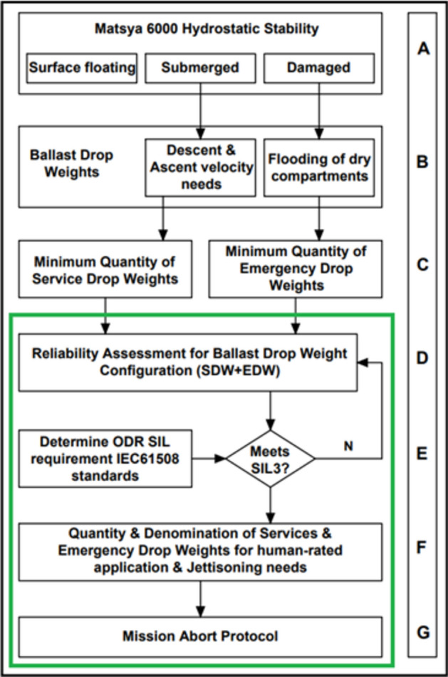
Methodology for identification of human-rated drop weight configuration.
Hydrostatic stability (stage A)
The general arrangement of Matsya 6000 is done by positioning the subsystems and components in the exo-structure taking into consideration of the weight and buoyancy, so as to achieve even keel condition on the sea surface and in the submerged conditions. The freeboard shall be 1.5 m (with a corresponding reserve buoyancy of 10% of the displacement) (Fig. 3).The stability criteria are met with the DNV rule requirement of metacentric height GM > 100 mm in surface condition and BG0 > 50 mm in submerged condition (Fig. 3). With ~ 8 tons of modular syntactic foam and main ballast tank with a capacity of ~ 3.2t, service and emergency drop weights, Matsya shall achieve a negative buoyancy of ~ 300 kg which shall offer a descend and ascend velocities of ~ 30 m/min. The top portion of Matsya is shaped to offer hydrodynamic drag resistances such that the submersible is stable when it re-emerges out of sea surface at the end of ascend.
Figure 3.

Profile view of Matsya6000.
Identifying minimum descend/ascend drop weight requirements (stages B and C)
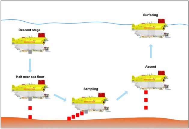
Based on the concept of operations (ConOps) evolved out of the hydrostatic behavior of Matsya6000 in the sea surface floating conditions and salinity profile up to 5500 m water depth 20(Fig. 4), the minimum weight and denomination of the dispensable service drop weights (SDW)required for the average descend/ascend speed of 30 m/min and sampling of 200 kg are defined in Table 1 and in Fig. 5. During descend, when Matsya 6000 which is negatively buoyant by 300 kg, due to the salinity increase its buoyancy reduces to ~ 100 kg when it reaches depths ~ 5500 m. When Matsya reaches closer to the desired altitude close to the sea floor, 2 × 50 kg of weights shall be dispensed to achieve near-neutral buoyancy. During the sampling operation (max 200 kg), 4 × 50 kg of weights shall be released to remain near-neutrally buoyant. During the start of the ascend, 300 kg (2 × 100 + 2 × 50 kg) shall be released. As Matsya6000 raises through the water column from 5500 m water-depth, due to the salinity decrease, its upward buoyancy decreases and reaches 100 kg (with a decrease of 200 kg due to salinity decrease).When Matsya6000 is in the sea surface, the main ballast tanks shall be emptied to achieve a free-board of 1.5 m. Thus, 10 numbers of independently-actuatable SDW each shall be distributed equally in the port and starboard sides.
Figure 4.

Profile view of Matsya6000.
Table 1.
Matsya6000 buoyancy change with (representative) depth in Indian Ocean.
| Subsystem | Change in buoyancy ΔB (kg) | ||
|---|---|---|---|
| 1000 m | 3000 m | 5500 m | |
| Personnel sphere | 21 | 57 | 94 |
| Syntactic foam | 12 | 22 | 28 |
| Variable ballast tanks | 3 | 9 | 14 |
| Others | 6 | 17 | 28 |
| Total | 42 | 104 | 164 |
Figure 5.
Concept of operation using service drop weights.
The change in buoyancy (ΔB) Eq. (1), of Matsya6000 with depth due to salinity variation for the subsystems is computed using the below relationship and the results are summarized in Table 1.
—(1).
where V is the Volume of the subsystem (m3), ρs is the seawater density at surface (kg/m3), ρd is the seawater density at depth (kg/m3), g is 9.81 m/s2, d is water depth and K is the bulk modules of the material in Mpa.
The minimum weight and denomination of the emergency drop weights (EDW) depends on the total volume of the four pressure-rated compartments (used for housing electrical and electronics systems) in Matsya exo-structure, which are susceptible to water flooding during damages or seal failure/s. Upon simultaneous flooding of all 4 pressure-rated enclosures, taking into consideration the floodable space, Matsya shall experience a loss of buoyancy (LoB) of 250 kg. To overcome this extreme LoB scenario, 1 × 250 kg of EDW is required. In the base configuration, total quantity of essential dispensable drop-weights (SDW + EDW) is summarized in Table 2.
Table 2.
Minimum SDW and EDW requirements.
| Phase | Weight (kg) | Quantity | Total Weight (kg) |
|---|---|---|---|
| SDW | |||
| Halting | 50 | 2 | 100 |
| Sampling | 50 | 4 | 200 |
| Ascend | 50 | 2 | 100 |
| 100 | 2 | 200 | |
| Total SDW | - | 10 | 600 |
| Total EDW | 250 | 1 | 250 |
|
Total SDW + EDW |
11 | 850 | |
On-demand reliability assessment for time-critical safety systems
Probabilistic estimates of operational reliability and safety reliability (SR)/ODR using numerical methods based on field-failure data and published failure models serve as a yardstick for comparing alternate technologies, continuous improvements and maintenance planning of the time-critical marine systems. The methodology/process adopted for computing ODR for safety–critical systems is summarized in Fig. 6. The initial step involves computation of the failure rate of the components or subsystems based on the field-failure databases. Failure models from standards, manufacturers estimate, historical data (heritage), handbooks and expert elicitation. The system functionality is modeled using fault trees based on bottom-top approach based on the system engineering inputs. The modeled fault trees are simulated for the required period (with the component/subsystem failure data as inputs) to obtain the probability of failure over the simulated period. The failure/degradation pattern serves as one the most critical inputs for the simulations. The computed failures rates serve as inputs for calculating the probability of failure-on-demand for safety critical systems.
Figure 6.
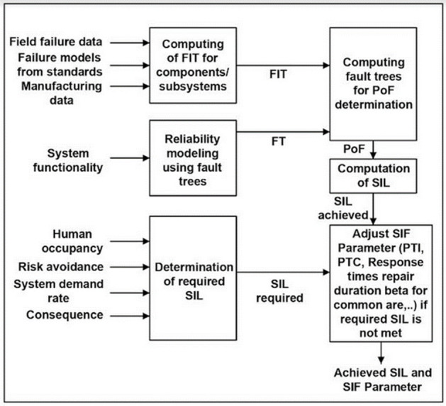
Methodology for computing the on-demand reliability.
IEC 61,508/11 is a standard proven framework for implementing instrumented safety systems using the principles of Safety Life Cycle and concepts of the Safety Integrity Level (SIL). Protection systems need to perform their intended operations on demand. The SIL defines the degree of safety protection required in the system and consecutively the safety reliability of the system necessary to achieve the function. SIL has four levels, 1 to 4. The safest being the highest level. Table 3 describes the various SIL levels with corresponding Probability of failure on-demand (PFD).
Table 3.
PFD for a high demand system.
| SIL | Probability of failure on demand (PFD/year) |
|---|---|
| 1 | > 10–6 to < 10–5 |
| 2 | > 10–7 to < 10–6 |
| 3 | > 10–8 to < 10–7 |
| 4 | > 10–9 to < 10–8 |
According to IEC 61,508 HSE standards, SIL level is computed based on the severity level (accident consequence), unavailability of alternate protection mechanism in place, human occupancy in the location to be protected and the likely demand on the system. Based on the severity level, the consequence parameter (C) can be catastrophic, extensive, serious, considerable, or marginal. Based on the availability or unavailability of alternate protection system, the parameter “P” is assigned the value of either 0 or 1, respectively. Based on the human occupancy, the parameter “F” takes the values 2, 1 or 0, corresponding to continuous, occasional and rare human presence. The demand rate (W) on the system depends on the frequency of demand on the safety system is shown in Table 4.
Table 4.
Factors for SIF demand rate.
| Demand rate | Factor ( W ) | |
|---|---|---|
| W9 | Often > 1/year | 9 |
| W8 | Frequent 1/1–3 year | 8 |
| W7 | Likely 1/ 3–10 year | 7 |
| W6 | Probable 1/10–30 year | 6 |
| W5 | Occasional 1/30–100 year | 5 |
| W4 | Remote 1/100–300 year | 4 |
| W3 | Improbable 1/300–1000 year | 3 |
Significance values are in Bold.
In the case of Matsya6000 operations, the sum of P, F and W is 10(1 + 2 + 7). The summed-up values are plotted against the consequence factor in the risk graph matrix shown in Table 5 to obtain the required level of SIL, from which, the ODR of the drop weight system configuration should comply with SIL3.
Table 5.
SIL level computation methodology.
| Consequence (C) | F + P + W | ||||||
|---|---|---|---|---|---|---|---|
| 1,2 | 3,4 | 5,6 | 7,8 | 9,10 | 11,12 | ||
| Catastrophic | F | NR | 1 | 2 | 3 | 4 | – |
| Extensive | E | NR | NR | 1 | 2 | 3 | 4 |
| Serious | D | NR | NR | NR | 1 | 2 | 3 |
| Considerable | C | NR | NR | NR | NR | 1 | 2 |
| Marginal | B | NR | NR | NR | NR | NR | 1 |
| Negligible | A | NR | NR | NR | NR | NR | NR |
Significance values are in Bold.
Assessment of on-demand reliability of base configuration (stage D)
In the base configuration (non-human rated), the SDW and EDW are configured to be released by the pilot from the personnel sphere. The hard-wired in-circuit components include operating power from the personnel sphere SIL4-rated 24VDC power supply network (which received input from main, auxiliary and emergency batteries), voltage level converters, toggle switches, cable harness, pressure-balanced oil-filled junction boxes (interfacing the personnel sphere hull penetrators and exo-structure systems) and the shape memory alloy (SMA)-based (Frangibolt/FB) drop-weight actuators21. All the in-circuit components are certified by DNV for human-rated application. The basic principle of the FB relies on a pre-compressed SMA tube and a titanium bolt with a special notched section which is positioned through the cylinder and restrained at either end. When heated up to a temperature of ~ 90˚C, the SMA undergoes a phase change (from martensitic to austenite) returning to its original size thus developing enough tensile force to fracture the notched section of the titanium FB. Redundant DC voltage powered heaters wrapped around the SMA generate heat for activation. The mechanism without any moving parts makes it reliable compared to other mechanisms. Since its invention in 1992 and its first application in spacecraft Clementine in 1994, the FB has attained unparalleled reliability (Fig. 7).
Figure 7.
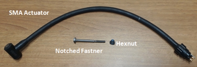
Underwater frangibolt and actuator used in Matsya6000.
Service drop weight
GRIF (GRaphical Interface for reliability forecasting) is a proven modelling and simulation software suite for determining the reliability and dependability—RAMS (reliability, availability, maintainability and safety)22. The tool is extensively used in the offshore sector for determining the health monitoring interval (HMI) needs of the tsunami early warning systems, optimization of subsystem design for deep- ocean submarines, dynamic positioning systems and offshore moorings23–25. We have used FTA and SIL modules of GRIF for modelling and simulations. In GRIF, advanced Boolean models employed for quantitatively computing the PoF and PFD of a system for a definite period uses binary decision diagram (BDD) technique. The Fault Tree (FT) is converted into BDD which represents an efficient storage of the Boolean equations for the top event. The BDD calculates exact top event probabilities based on disjoint decomposition compared to traditional kinetic tree approaches that employ many approximations such as truncation, rare-event approximations, and intermediate minimal cut steps and delete term approximations26. The on-demand reliability (ODR) for a SDW computed using GRIF probabilistic SIL ODR modeling and simulation software with failure-in-time (FIT) data from FIDES, OREDA, MIL and relevant field failure databases (Table 6) is shown in Fig. 8.It is identified that a SDW has an average PFD of 2.12 × 10⁻⁷ in a period of 1 year. In the failure tree, as examples, Evt10242 represents basic event, Or714 represent group events (multiple events below for representation), Evt6887 represent common events, Or715 is used to indicate that the output event occurs if and only if at least one of the input events occurs, and And571 indicates that an event occurs only if all input conditions are met. Every basic event is provided with industry-reported failure pattern as an input, such as exponential, Weibull etc.
Table 6.
Failure-In-Time data used for analysis.
| Component | Failure rate(λ) | Source of data reference |
|---|---|---|
| Subsea cable harness | 244 | OREDA 27 |
| Enclosure with O-ring seals | 1000 | |
| Penetrator | 715 | |
| PBOF junction box | 244 | |
| Terminal block | 50 | |
| DC-DC converter | 75 | FIDES28 |
| Battery management system (BMS) | 6666 | |
| Selector switch | 100 | |
| Li-Po battery | 4000 | Boeing29 |
| Lead acid battery | 2300 | US-DoE 30 |
| Shape memory alloy actuator | 100 | EBAD31 |
| Acoustic positioning system | 22,831 | Evologics 32 |
Figure 8.
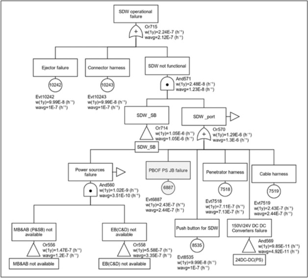
PFD computation for SDW.
The relationships for calculating the PFD in OR, AND is expressed in below Eqs. (2) and (3).
| 2 |
| 3 |
Emergency drop weight
Taking into consideration the weight and volume constraints on-board Matsya6000, the reliability of the emergency drop weight actuating systems are improved based on the latest technologies available in the marine industry. In the implemented configuration, the EDW could be actuated in three modes as described below. The Acoustic Transponder and Responder (ATRR) is customized to Matsya6000 EDW requirements (Fig. 9). The architecture of the EDW is shown in Fig. 10.
Submersible pilot (like in SDW).
From the deployment ship using acoustic release transponder feature in ATRR (with built-in battery).
Submersible pilot using responder feature in ATRR.
Figure 9.
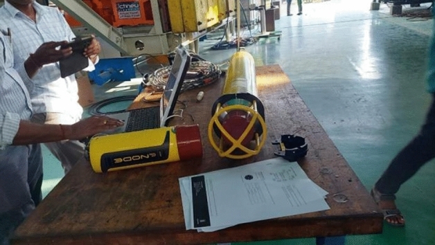
Testing of the customized ATRR system.
Figure 10.

Configuration of EDW with three options for operation.
The On-demand reliability (ODR) for the EDW is computed using GRIF with failure-in-time (FIT) data (Table 6) is shown in Fig. 11. It is identified that the EDW has a PFD of 2.35 × 10⁻⁹.The gate KoutN979 indicates that two failures could be tolerated and third failure impairs the operation of the EDW. Thus, the failure rate of the EDW is 5.23 times lower than the SDW.
Figure 11.
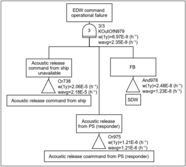
PFD computation tree for theEDW.
ODR for basic drop-weight configuration
The ODR for the basic (non-human rated) drop-weight configuration comprising of 10 SDW and 1 EDW is computed (Fig. 12) through modeling and simulations. It is identified that with the basic configuration, the PFD is 2.39 × 10⁻⁶. Thus, the configuration meets only SIL1 of safety reliability.
Figure 12.
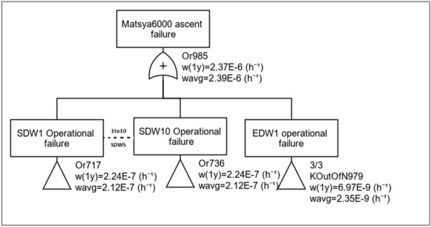
PFD computation tree for the basic configuration.
Realizing human-rated configuration for the mission (stages E and F)
Phase 1: Descend
During the descend phase, when the mission has to be aborted and Matsya needs to surface, all the 10 SDW (600kgs) has to be dropped to attain an upward buoyancy of 300 kg. Further, in case of an ascend along with 4 dry compartments in flooded condition (worst case scenario), 10SDW + 1EDW is essential. As the base configuration with minimum number of drop weights (10SDW + 1EDW) does not comply with SIL3 (Fig. 12), the configuration is improved taking into consideration the weight limitation, which is critical for the battery-powered Matsya6000.
The additional features include inclusion of one additional EDW and jettison feature for the trim system. The trim system is chosen for jettisoning taking into account its location in the bottom (so that it could be released easily) and it does not affect the basic submersible operations. The ODR analysis is carried out and improved configuration has a PFD of 4.5 × 10⁻⁸, which complies with SIL3 (Fig. 13).
Figure 13.
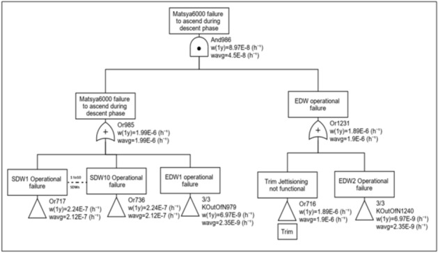
PFD computation for descend phase.
The ODR-weight trade-off studies for the above configuration are summarized in Fig. 14. The details of each improved configuration are given in Table 7. It is evident that the configuration D with 10 SDW+ 2 EDW+ Trim Jettison provision meets the required SIL3 ODR. Further incorporation of EDW does not significantly improve the ODR, but results in increase in weight of Matsya6000, which shows the risk has been reduced to ALARP.
Figure 14.
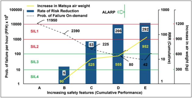
ODR Vs weight trade-off.
Table 7.
Configuration with increasing improvements.
| Config | Description |
|---|---|
| A | Configuration with 10 SDW + 1 EDW (without ATRR) |
| B | Configuration A + ATRR feature for EDW |
| C | Configuration B + 2nd EDW (with ATRR) |
| D | Configuration C + Trim Jettison |
| E | Configuration D + 3rd EDW (with ATRR) |
Phase 2: halting at 100 m altitude from the seafloor
As Matsya6000 approaches the ocean floor, in order to halt, two numbers of SDW have to be released. The ODR for configuration computed using GRIF SIL tool is shown in Fig. 15. The gate kOutofN985 indicates that 8 SDW failures are acceptable. The gate And1231 indicates that during flooding of dry compartments, either EDW2 shall be dropped or trim system shall be jettisoned. It is identified that, during halting phase, the configuration has a PFD of 1.23 × 10⁻⁸, which is in SIL3 category.
Figure 15.

PFD computation for halting phase.
Phase 3: seafloor sample collection
During the sampling collection phase, four numbers of SDW need be released to remain in neutrally buoyant condition. Prior to sampling 8 numbers of SDW shall be available after dropping 2 SDW to halt. The ODR for configuration computed using SIL GRIF tool is shown in Fig. 16. The gate kOutofN985 indicates that 4 SDW failures are acceptable. The gate And1231 indicates that during flooding of the dry compartments, either EDW2 shall be dropped or trim system shall be jettisoned. It is identified that, during the sample collection phase, the configuration has a PFD of 1.23 × 10⁻⁸, which is also in SIL3.
Figure 16.
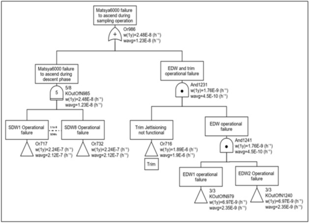
PFD computations for sampling phase.
Phase 4: ascend phase
After the sampling phase, having cumulatively released 6 numbers of SDW (2 for halt and 4 for sampling), Matsya6000 has to release 4 SDW to initiate the ascend. The ODR for configuration is computed (Fig. 17). The gate kOutofN985 indicates that 1 SDW failure is acceptable. It is identified that the configuration has a PFD of 1.23 × 10⁻⁸, which is in SIL3 category.
Figure 17.

PFD computation for ascend phase.
Defining mission abort protocol (stage G)
The degradation-based MAP is used for defining the abort criteria. Figure 18 shows the ruggedness of the drop-weight system architecture in the event of flooding of 4 dry compartments and 2 PBOF compartments (Table 8). It can be seen that the drop weight system is immune to simultaneous flooding of 4 dry compartments (A to D), and remain in SIL3, and the mission need not be aborted. Damage to penetrator junction boxes (E, F and G) degrades the safety reliability to SIL2 and SIL1 levels, and subsea mission needs to be aborted.
Figure 18.
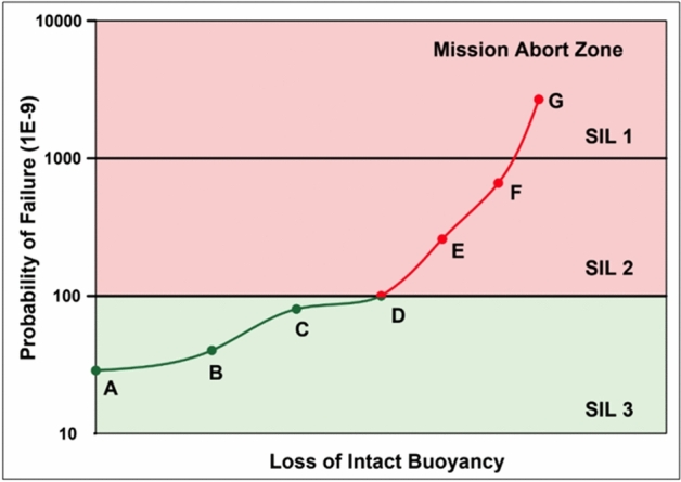
Degradation of the drop weight system during flooding.
Table 8.
Loss of buoyancy scenarios (ref Fig. 18).
| Scenario | Description |
|---|---|
| A | Intact buoyancy |
| B | One pressure-rated enclosure flooding |
| C | Two pressure-rated enclosure flooding |
| D | Four pressure-rated enclosure flooding |
| E | Penetrator Junction Box (P) flooding |
| F | Penetrator Junction Box (SB) flooding |
| G | Both Penetrator Junction Boxes flooding |
Conclusion
Ensuring human safety is the key requirement for deep-ocean human occupied scientific submersibles. The optimum combination of service drop weights, emergency drop weights and jettisoning systems that has to ensure the safety during various stages of the subsea mission, including descend, halting at pre-defined altitude, sea floor sample collection and ascend has to be identified, so that it design complies with a human-rated needs. Whenever, there is degradation/unavailability of the drop weights and jettisoning systems, the degraded conditions under which a subsea mission should be aborted has to be defined in prior through a well-defined mission abort protocol. This paper proposes a first-of-its kind idea for determining a safety-centered descend-ascend drop weight configuration and mission abort criteria for deep-ocean human scientific submersibles. With specific reference Matsya6000 submersible architecture, based on IEC61508 SIL standards for time-critical systems, failures of all the four exo-structure mounted pressure rated enclosures leads to mission failure, while further degradations are identified as life-critical.
The novel concepts presented include:
Application of HSE IEC61508 standards for determining the safety integrity levels.
Identify probability of failure during all phases of the mission based on probabilistic failure analysis with field-failure data.
Evaluate various submersible subsystem failure sceneries that demands subsea mission abort.
The methodology adopted could be used for identifying the ballast drop-weight, jettisoning and mission abort situations for deep-ocean human-rated systems. However, it is required to model the submersible-specific drop weight configuration and simulate the probability-of-failure-on-demand based on reported component field failure data.
Acknowledgements
The authors gratefully acknowledge the support extended by the Ministry of Earth Sciences, Government of India, in encouraging this research under the Deep Ocean Mission.
Author contributions
Palaniappan M. wrote the concept of methodology for Drop weight mechanism Bala Naga Jyothi V. has prepared the Figs. 7 to 17 Tamshuk Chowdary. has prepared the bouyancy calculation Sathianarayanan D. and Vedachalam N. has wrote the main manuscript.
Data availability
All data generated or analysed during this study are included in this published article.
Competing interests
The authors declare no competing interests.
Footnotes
Publisher's note
Springer Nature remains neutral with regard to jurisdictional claims in published maps and institutional affiliations.
References
- 1.Rona, P. A. Deep-diving manned research submersibles. Mar. Technol. Soc. J.33(4), 13–25. 10.4031/MTSJ.33.4.3 (1999). 10.4031/MTSJ.33.4.3 [DOI] [Google Scholar]
- 2.Du, M., et al. "Geology, environment, and life in the deepest part of the world’s oceans." The Innovation 2.2 (2021). [DOI] [PMC free article] [PubMed]
- 3.Ramesh, R., et al. "Fault-tolerant control network architecture of deep water Manned submersible MATSYA 6000." OCEANS 2022-Chennai. 1–5.IEEE, 2022. 10.1109/OCEANSChennai45887.2022.9775528.
- 4.Part 5 Types of UWT systems - Chapter 6 Manned submersibles, Rules for classification, DNV, (Edition. July 2019).
- 5.Smith, D. J., & Simpson, K. G. The safety critical systems handbook: a straightforward guide to functional safety: IEC 61508 (2010 Edition), IEC 61511 (2015 edition) and related guidance. Butterworth-Heinemann. (2020).
- 6.Clark, R. P., and C. P. Brown. Selection of Descent and Ascent Method for the WHOI RHOV. In SNAME Maritime Convention. D011S001R003. SNAME. (2008).
- 7.Vedachalam, N., Ramadass, G. A. & Atmanand, M. A. Reliability centered modeling for development of deep water Human Occupied Vehicles. Appl. Ocean Res.46, 131–143. 10.1016/j.apor.2014.03.001 (2014). 10.1016/j.apor.2014.03.001 [DOI] [Google Scholar]
- 8.Kapurch, S. J. System Engineering in NASA systems engineering handbook (Ed.). 3–17(Diane Publishing, 2010).
- 9.Hyle, C. T., Foggatt, C. E., & Weber, B. D. Apollo experience report: Abort planning (No. NASA-TN-D-6847). (1972).
- 10.Chai, X., Chen, B. & Zhao, X. Optimal Mission Abort Decisions for Multi-Component Systems Considering Multiple Abort Criteria. Mathematics11(24), 4922. 10.3390/math11244922 (2023). 10.3390/math11244922 [DOI] [Google Scholar]
- 11.Zhang, Yanping, et al. Joint multi-objective optimization method for emergency maintenance and condition-based maintenance: Subsea control system as a case study. Reliab. Eng. Syst. Saf. .110307. (2024). 10.1016/j.ress.2024.110307
- 12.Zhang, W., Zhang, X., He, S., Zhao, X. & He, Z. Optimal condition-based maintenance policy for multi-component repairable systems with economic dependence in a finite-horizon. Reliab. Engi. Syst. Saf.241, 109612. 10.1016/j.ress.2023.109612 (2024). 10.1016/j.ress.2023.109612 [DOI] [Google Scholar]
- 13.Levitin, G., Xing, L. & Dai, Y. Mission abort policy for systems with observable states of standby components. Risk Anal.40(10), 1900–1912. 10.1111/risa.13532 (2020). 10.1111/risa.13532 [DOI] [PubMed] [Google Scholar]
- 14.Levitin, G., Finkelstein, M. & Dai, Y. State-based mission abort policies for multistate systems. Reliab. Engi. Syst. Saf.204, 107122. 10.1016/j.ress.2020.107122 (2020). 10.1016/j.ress.2020.107122 [DOI] [Google Scholar]
- 15.Chai, P., & Qu, M. Human mars mission transit abort options for ballistic high thrust and hybrid transportation systems. ASCEND 2022 .4374. (2022). 10.2514/6.2022-4374
- 16.Chai, P. R. P., & Rucker, M. A. Mars mission abort considerations (2024).
- 17.Phillips, A. B., et al. Autosub long range 1500: A continuous 2000 km field trial. Ocean Eng..280, 114626. (2023). 10.1016/j.oceaneng.2023.114626
- 18.Vedachalam, N., Ramesh, R., Jyothi, V. B. N., Ramadass, G. A. & Atmanand, M. A. An approach to operational risk modeling and estimation of safety levels for deep water work class remotely operated vehicle—A case study with reference to ROSUB 6000. J. Ocean Eng. Sci.1(2), 109–118. 10.1016/j.joes.2016.03.005 (2016). 10.1016/j.joes.2016.03.005 [DOI] [Google Scholar]
- 19.Narayanaswamy, V. et al. Reliability-centered development of deep water ROV ROSUB 6000. Mar. Technol. Soc. J.47(3), 55–71. 10.4031/mtsj.47.3.3 (2013). 10.4031/mtsj.47.3.3 [DOI] [Google Scholar]
- 20.Thornton, B. Sizing drop weights for deep diving submersibles taking into account nonuniform seawater density profiles. IEEE J. Oceanic Eng.45(3), 979–989. 10.1109/JOE.2019.2898070 (2019). 10.1109/JOE.2019.2898070 [DOI] [Google Scholar]
- 21.Ferris, M., & Haslehurst, A. (2014, May). The use, evolution and lessons learnt of deployable static solar array mechanisms. In The 42nd Aerospace Mechanism Symposium. 20150004077
- 22.GRaphical Interface for reliability Forecasting (GRIF). https://grif.totalenergies.com/en (2021).
- 23.Vedachalam, N. & Ramadass, G. A. Reliability assessment of multi-megawatt capacity offshore dynamic positioning systems. Appl. Ocean Res.63, 251–261 (2017). 10.1016/j.apor.2017.02.001 10.1016/j.apor.2017.02.001 [DOI] [Google Scholar]
- 24.Srinivasa Kumar, T., Venkatesan, R., Vedachalam, N., Padmanabham, J., & Sundar, R. Assessment of the reliability of the Indian Tsunami early warning system. Mar. Technol. Soc.J., 50(3), 92–108. (2016).10.4031/MTSJ.50.3.12
- 25.Venkatesan, R., et al. Reliability analysis and integrity management of instrumented buoy moorings for monitoring the Indian Seas. Underw. Technol. 33.2, 115–126. (2015).10.3723/ut.33.115
- 26.Folleau, C. & Vedachalam, N. Methodologies for Reliability and Functional Safety Assessment of Offshore Systems. Mar. Technol. Soc. J.56(2), 93–106. 10.4031/MTSJ.56.2.8 (2022). 10.4031/MTSJ.56.2.8 [DOI] [Google Scholar]
- 27.OREDA. Offshore reliability data handbook by SINTEF and group of oil and gas companies. Det Norske Veritas, Norway. 874. https://oreda.com/
- 28.Guide, F. I. D. E. S. (2009). Reliability methodology for electronic systems. FIDES group, 465.
- 29.Williard, N., He, W., Hendricks, C., & Pecht, M. Lessons learned from the 787 dreamliner issue on lithium-ion battery reliability. Energies, 6(9), 4682–4695. (2013).10.3390/en6094682
- 30.De Anda, M. F., Butler, P. C., Miller, J. L., & Moseley, P. T. Reliability of valve-regulated lead-acid batteries for stationary applications (No. SAND2004–0914). Sandia National Laboratories (SNL), Albuquerque, NM, and Livermore, CA (United States). (2004). https://www.osti.gov/servlets/purl/918779
- 31.EBAD. TiNi™ Subsea Frangibolt® Actuator.https://www.ebad.com/tini-subsea-frangibolt/
- 32.Jyothi, V. B. N., Ramesh, R., Vedachalam, N. & Ramadass, G. A. Assessment of the Technological Maturity of Manned Submersible Navigation Positioning Systems. Mar. Technol. Soc. J.55(5), 129–137. 10.4031/MTSJ.55.5.4 (2021). 10.4031/MTSJ.55.5.4 [DOI] [Google Scholar]
Associated Data
This section collects any data citations, data availability statements, or supplementary materials included in this article.
Data Availability Statement
All data generated or analysed during this study are included in this published article.