

Abstract
The work reports the proposed development of the laminated carbon fiber-reinforced polymer composites (CFRP), at a uniaxial angle as a primary bend clamp material assembly of the offshore gas lift pipelines. Generally, the clamps are utilized to repair the defect of the metallic pipelines due to their practical and mechanical strength. The existing bend clamp model poses challenges especially when applied to the J-tube bending side due to mechanical buckling and corrosion. This study evaluates the effect of laminated CFRP subjected to uniform uniaxial and in-plane compression on API 5 L X52. Several tests, including tensile, bend, and impact tests, are chosen to assess the effect of multiple and thick carbon layers to improve the clamp's mechanical properties. Scanning electronic microscope (SEM) intends to reveal the surface characterization of carbon fiber clamp. The result shows that laminated carbon fiber increases the durability and mechanical properties of the bend clamp for two weeks. The tensile test result shows that the uniaxial orientation has the highest tensile strength of about 2000N and is affected by the strong interfacial bond between the fiber and metal layers. The high impact energy of 2242 ± 0.001 J of the same orientation shows the stability of the clamp under unprecedented dynamic load and enhances the safety. The SEM result at uniaxial shows the resistance towards fracture has increased and was initiated from the air pocket in the composite.
Keywords: Carbon-fiber clamp, Bend side pipelines, Finite element analysis, Hoop stress, Stress-strain analysis, Material characterization
1. Introduction
The oil and gas industry has rocketed recently and is one of the prominent sectors that increase the national energy need and contribute to developing the country's income. Oil and gas extraction doubled in size for ten years from 2003 to 2013 to more than 70 % to support the hydrocarbon supply, as reported in Ref. [1]. Safety at their facility and machinery is essential to ensure smooth operation to prevent unnecessary shutdowns and sudden failures [2]. It is estimated that about 80 % of oil exploration and production failures are due to material deterioration driven by corrosion. The preferential possibility is due to metal loss and the stress types of material accompanied by corrosion. In addition, the oil spill has recently been seen as a primary threat to human activity and can damage and affect equipment and facilities. The release of hydrocarbon when the leak appears provides unnecessary loss of production while polluting the environment. While the effect on the environment on fishing and tourism was approximately beyond USD 5.5 billion in 2010, the other total expense for cleaning up the impact was nearly USD 1286 per tonne, as reported in Ref. [3].
As such, it is critical to gain detailed causes and reasons for corrosion and provide recommendations to hinder similar incidents in the forthcoming production process [[4], [5], [6]]. With the general type environment in an offshore location, the electrochemical reaction at different anodic and cathodic sites represents the corrosion process and causes the surface deterioration of general corrosion. Under harsh conditions such as high chloride content, acidic environment, and carbon dioxide corrodents, the corrosion rate of subsea pipelines increases rapidly. Due to the continuous corrosion process, material depletion is inevitable and potentially causes an oil spill from the unseen pitting corrosion [7]. Protecting from corrosion becomes critical to preventing the leak event or damage.
A bend clamp is the most practical solution to prevent progressive leak results. The bend clamp is an attractive and valuable instrument for repairing corroded and leaked pipelines commonly used in oil and gas facilities [8]. The work of [9] emphasizes the clamp design as a key factor in assembling the clamp according to ASME PCC-2 standards at various pressure and temperature ranges to ensure the pressure exceeds the pressure on the leaked area. An applied higher pressure is compulsory for better insulation in the leak area. The ageing facility in brownfield oil and gas industry increases the potential of coating defects and low CP even though a stricter and continuous monitoring activity is implemented [10]. As such, the possibility of a leak to occur is inevitable and requires a preventive action to cover the unprecedented leak.
Notwithstanding, the mechanical properties, durability, and ease of installing the clamp should be considered, including the possibility of using materials such as carbon fiber. This work proposes laminated carbon fiber on the surface of metallic clamps to modify their mechanical properties and resistance against corrosion. Regretfully, the existing clamps exhibit poor fatigue and low corrosion resistance, which is a disadvantage to their application in offshore conditions. The rationale of this research is to make full use of the laminated carbon, to minimize the production expense of CFRP, and to shorten the installation period as a promising strategy for achieving optimal repair performance.
In the previous research, using mechanical clamps to remedy the pipeline's leak using bend clamps in oil and gas was intense. The report of [11] shows that the clamps are prone to leak due to rupture and require a stringent inspection to ensure safety in subsea pipelines. They recommend implementing a repair-leak-repair cycle to lessen the potential fracture in the same leak position. While installing the conventional leak sealing clamp is essential to hinder the leak in sour gas for unnecessary production shutdown, the leak sealing enclosures are equally vital to repair the leaking on the pipes, flanges, and valves [12]. Laminating the carbon on the reinforced polymer by stacking carbon on a metallic clamp forms a sandwich structure, which is adventurous.
Another type of pipeline repair system is the implementation of grouted sleeves that solely focus on the dent defects, especially for the structural tubular steel. Tension-tension fatigue is a prime factor to consider when designing the carbon/glass clamps due to the disbondment at the interface of glass and carbon fiber-reinforced polymer, which leads to premature material failure, as studied by Ref. [13]. However, the study did not observe the distinct modification CFRP when the interlayer sticking carbon was assembled at various angles.
Hence, this study attempts to cover the gap by offering a new design to evaluate the CFRP repair solution equivalent to a clamp metallic base with high corrosion resistance, ease of fabrication, and modification. The objective of this research is to unveil the stacking carbon fiber at various angles of 0°, 45°, and 90°, which can yield satisfactory CFRP performance at the J-tube position for offshore clamp purposes and improve the strength of composite material. Accordingly, the research elaborates on the performance of the carbon fiber using scanning electronic microscopes to reveal the surface modification upon the layering condition of layering system in the carbon fiber of API 5 L X52.
The limitation of this study is related to the application of the carbon fiber that comprises five layers before it is in contact with the metallic clamps. In addition, the selected orientation of carbon is restricted at uniaxial, 45, and 90° to evaluate the optimum modification of their mechanical properties. In this case, the continuous five fiber layers are oriented omnidirectionally without depositing the active materials on the carbon fibers.
2. Materials and methods
2.1. The raw material and design plan
The object of this study is the carbon fiber embedded into the metal layer of API 5 L X52 comprises two half-cylindrical shells (see Fig. 1b) with flanges joined by bolts (see Fig. 1a), as illustrated below. The shell and flanges thickness were labeled with the letter, S and F.
Fig. 1.

The proposed bend clamp model made by carbon fiber composite material (a) Bend clamp (b) half-cylindrical shells.
In this work, the design development was conducted at the J-tube of the 5 dimensions radius pipelines. The clamp was designed to achieve the standard oil and gas industry with mechanical pressure at 7 MPa or 1000 psi. The value aligns with the maximum force permitted during the repairing window. Equation (1) shows the calculation of the shell thickness of the clamp [14],
| (1) |
In the above equation, S, Pi, Di, E, and ε correspond to shell thickness, internal pressure, internal diameter, modulus elasticity of the material, and hoop strain.
2.2. Carbon fiber reinforced polymer clamp fabrication
Five carbon fibers of ESTOWRAP 300 were purchased from ESTOP® and were prepared had a typical high-strength carbon fiber sheet. The product's density was 300 g/m2, and the design thickness and the width were 0.166 mm and 50 cm (see Fig. 2). Meanwhile, the modified CFRP clamp was fabricated using an adhesive agent to adhere to a layer of carbon fiber to bond with the mechanical clamp. The unique difference in this work is the utilization of the orbital sander in place of sandpaper to create a surface profile and achieve maximum bonding, similar to the work of [15]. In this work, the carbon fiber underwent uniform compression by weaving them used in the textile industry at a rate of 0.6 kg/m2. The model was a square sheet with a side length of 500 mm. The primary intention of adding epoxy adhesive was to improve the bond's durability and strength between the carbon fiber and the API 5 L X52 metal [16]. The composition of the fiber sheet material is presented (see Table 1). The fiber adhesive was cured and dried at 40 °C in the air for half an hour and was treated with 0.5 vol oxygen at 150 °C for 5 min before adding the adhesive.
Fig. 2.
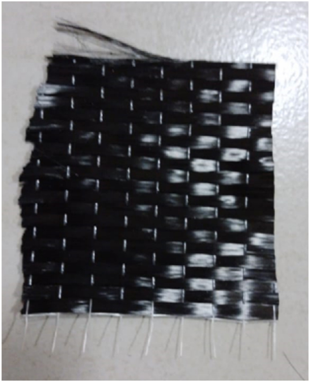
The carbon fiber.
Table 1.
The mechanical properties of fiber sheet comparison.
| Fiber areal weight (g/m2) | Thickness (mm) | Tensile Strength (MPa) |
Tensile modulus (GPa) | Elongation break (%) | |
|---|---|---|---|---|---|
| Value | 300 | 0.166 | 4900 | 230 | 2.1 |
The layer-to-layer carbon fiber formation to form the carbon-based clamp was made by adding the resin as the adhesive agent with commercial wrap primer and resin (see Fig. 2). In this case, the lay-ups of the sheet are subjected to uniform uniaxial to achieve the in-plane compression at 0, 45, and 90° directions on the surface of the metallic clamp.
In this instance, the uniaxial direction was set up when the continuous alignment of the fiber has the principal direction with the laminate direction of the fibers at 0°. Moreover, the plies are oriented at 45° degrees when the fibers are aligned at right angles to the direction of the principal lamination. Table 2 shows the adhesive properties provided by the manufacturer, including the primer and resin composition.
Table 2.
The technical and mechanical properties of adhesives.
| Primer | Resin | |
|---|---|---|
| Adhesive strength (MPa) | >1.5 | >1.5 |
| Shear strength (MPa) | >30 | >30 |
| Compressive strength (MPa) | >60 | >60 |
| Flexural strength (MPa) | >40 | >40 |
| Viscosity (cps @25 °C) | <2000 | <2000 |
| Application temp (0C) | 5–35 | 5–35 |
| Mixing ratio | 1:2 | 1:2 |
Based on Table 2, the composition of the resin and primer was the same to ensure homogeneity in the fabricated clamp. According to the product data sheet of ESTOWRAP, the curing time was 30 min with a mixing ratio of 1:2 to ensure the fabrication completion.
2.3. Tensile test
Measuring tensile strength and the deformation performance of the clamp was subjected to standard ASTM D638 [17] using tensile strength serial number 318 and digimatic caliper serial number A15119938. The condition was conducted at 24.5 °C and a relative humidity of 55 %. The clamp was composed of the CRFP of API 5 L X52 alloy. The width and length of the narrow section of the specimen were 13 mm and 57 mm. The width and length overall of the specimen were 20 mm and 165 mm. Meanwhile, the gage length was 25 mm with the distance between grips being 50 mm and 115 mm. Nine parallel specimens were used in this study. The tensile test was performed using the ASTM D638 standard using Universal's tensile test machine. The specimen was assembled and cast. During the casting process, the base and upper layer of the sample were made of aluminum, while the mid layer was prepared from Teflon (see Fig. 3).
Fig. 3.

The tensile test specimen.
In practice, the bolts assemble the specimen at its center. The electrical screwdriver was used to tighten the bolts where the bottom bolt section was in contact with the upper surface of the flange. The tensile strength and the performance of the clamp connection were performed under horizontal tension transmitted by the machine. The specimen tensile test studied in this research was tailored to the engineering fabrication practice. The accuracy of the test was controlled to ensure the pressure applied in the test specimen was approximately equal to the reported combined and expanded uncertainty at k = 2 and the estimated confidential level of 95 %.
2.4. Impact and bend test
Upon the fabrication of CFRP, it is prime to assess the stability of material to absorb energy due to sudden loading conditions and to ensure the surface of the fabricated CFRB is free from cracks or defects; the impact and bend test was conducted. The impact test was conducted and adhered to the ASTM E−23, similar to the work of [18] at 24.5 °C and relative humidity at 55 % using Izod Charpy Impact Instrument (Fig. 4a) with serial number 35532 and digimatic caliper A15119938. In this engineering practice, each specimen was firmly secured in the center of the fixture by tightening four screws. The Charpy impact test was selected using the specimen dimension of 10 x 10 × 60 mm V-notch depth of 2 mm at 450 angle, as illustrated in Fig. 4b.While the bend set-up was given in Fig. 4c.
Fig. 4.

The test experiment (a) set-up of impact specimen (b) prepared impact test specimen (c) The bend test set up (d) bend test specimen.
The calculated energy was calculated using equations (2), (3)).
| (2) |
| (3) |
In the above equation, IS is the Impact Strength, E is the elasticity modulus, J0 is the initial energy of the load, Ji is the final energy of the load. Upon completion of the impact test, the specimen underwent a three-point bending test using a uniaxial testing T-machine adherent to ASTM D790 [19] and the result was given in Fig. 4d. The prepared sample was 17 mm × 12.7 mm x 3.2 mm. This work's loading rate was 1 mm/min to produce the load-displacement values. The support radius and the loading nose were 6 mm, and the two support distances were set to 70 mm, corresponding to the 3.2 mm thickness of the CRFP specimen. The length of the support and nose was 17 mm to ensure the width of the specimen was included.
2.5. Surface evaluation of the carbon fiber
In this work, the surface morphology was conducted to evaluate the layer-to-layer of the carbon fiber on the surface of the specimen surface modification. The specimen material was prepared using 10 mm × 10 mm and low-velocity impact or low-speed diamond cutting based on the standard ASTM E986 [20] and ASTM F1372 [21] and comparable to Ref. [22]. The carbon fiber configuration was observed using FESEM FEI Inspect F50. The morphology of the fabricated sample was measured at 298 K using a tested acceleration voltage of 30 kV, and the maximum magnification was 2000 times.
3. Results and discussion
3.1. Results of carbon-fiber as the material in bend clamp
Fig. 5 shows the result of adding carbon fiber in the bend clamp at angles 0, 45, and 90° when the coating application undergoes.
Fig. 5.

The coating result of carbon fiber at various angles (a) uniaxial (b) 45° (c) 900
It is possible to note that the uniaxial composite provides better adhesion since it improves the contact area and load transfer [23]. Based on Fig. 5a, the strong adhesion at 0° is influenced by the strong physical field interaction amongst the ply to provide better interfacial interactions between the layers. With this in mind, the fibers are completely bonded, avoid slippage at unidirectional lamination, and provide equal strain. This finding is comparable to the result in Ref. [24], where improvements were made to the layers of fibers in the fabric lamination. In addition, the uneven distribution of the coating material influences the mechanical properties of the fabricated material. In this case, the anisotropic and fiber alignment becomes a key to harvesting the mechanical energy of the composition.
On the one hand, it is predicted that when the ply's position is parallel, it exploits the inherent strength on the same axis. On the other hand, the orientation of the primary stress load would be against the force within that direction. The combination of the two is attributed to the additional mechanical energy when the ply was embedded in a metallic clamp to reduce the lateral deformation [19]. Based on the structure, the combination of 45° plies shows the orientation of the fabricated clamp improve mechanical strength. At the same time, lower delamination may appear, weakening the strength of the interlaminar shear of the fabricated clamp (see Fig. 5b) [25]. With this in mind, a possible flaw leads to unprecedented deformation when the clamp protects the bending position of the leaked pipelines. Moreover, the challenge of perpendicular ply orientation is a weaker interface between the layers with lower energy absorption (see Fig. 5c)
3.2. The tensile test result
Tensile tests are conducted on specimens to validate their practicability to serve as bend clamps by acquiring their mechanical characteristics and behaviour. Fig. 6 shows the result of the prepared specimen after the tensile test to showcase the carbon layer's effect on the clamp's mechanical properties.
Fig. 6.

The tensile test result of the impregnated carbon on the substrate (a) Uniaxial (b) 45° (c) 90°.
According to Fig. 6, it is possible to note that the uniaxial specimen has the most significant tensile strength, nearly 2000N, among the other test samples. As the orientation of the ply changes from 0° to 90°, the stress level gradually decreases from around 20000 N to less than 2000 N and has a direct proportionality with the decrease of strain. The reported strain values approximately are 6.8 mm, 6.5 mm, and 0.9 mm for all angles with the same number of carbon ply to elucidate the elastic nature of the impregnated clamp. For this reason, the applied stress influences the material to experience less deformation to decrease the strain. Based on the above fact, the deformation mode of the entire angle positions is more pronounce in elastic.
Table 3 agrees with the result in Fig. 6 to show the effect of uniaxial fiber orientation on the metal surface.
Table 3.
The reported measurement of tensile test result.
| Direction | Length specimen before elongated (cm) | Length specimen after elongated (cm) | Elongated (cm) |
|---|---|---|---|
| Uniaxial | 155 | 168 | 13 |
| 45° | 155 | 165 | 10 |
| 90° | 155 | 162 | 7 |
At the uniaxial fiber, the width and thickness of the specimen shrink as more tension increases with the most extended elongation of 13 cm, compared to the initial length of the specimen (Table 3). The failure mode of the uniaxial direction is the onset of the debonding of carbon fiber layers, which provides a higher extension of various strains. The fracture of the gauge area is evident and closer to the middle area. It fails after the tension was applied at 3.5 cm, showing the elastic nature of the material. On the contrary, it is also possible to note that at 90°, the deformation is remarkably achieved while the higher stress causes the elongation at uniaxial to form necking. It results from the increase of bending forces, which confirms the result in Fig. 7.
Fig. 7.

The macro photography result of the sample at (a) uniaxial (b) 45° (c) 900
It is imperative to evaluate the effect of micropore defects on the tensile strength in responding to the stress applied to the bend clamp and study their damage behaviour. The below view is the magnification of the top view image to showcase the more detailed micropores in each test specimen (see Fig. 7). In the entire test specimen, the presence of micropores is in the longitudinal direction and the formation of micropores originally induces crack propagation and lower the tensile strength of the composite. After impregnation of the carbon fiber on the surface of the metal, a uniform particle distribution and several fractured particles are observed in the composite. The qualitative analysis indicates the volume fraction of the defects is estimated at 10 % with two sources of microproces from the surface of metals and the voids near the carbon fiber.
The void arises from the weaving uniform compression, as stated in Section 3.2 [26]. In addition, the strong interface bonding between the fiber and the metal is obvious in the uniaxial specimen to indicate less stress concentrator (micropores) around the tiny defects when they are oriented longitudinally. Likewise, at the acute and right angle orientation, a weaker interface bond appears to reduce the effective cross-sectional area of the fabricated clamp to bear the applied stress load (see Fig. 7 b and c). This fact agrees well with a smaller tensile stress value at around 1800 and 500 N given in Fig. 6b and c. Moreover, the uniaxial orientation tends to inhibit the crack propagation along the direction of pores due to the formation of a barrier to disrupt the cracks to propagate and disseminate the stress concentrator [27] (see Fig. 7a). It is imperative to note, the strong interface bonding is associated with more inhibition to transfer the load applied on the clamp from the carbon matrix to the particle.
3.3. Impact test result
In this work, the result unveils the stress-strain curve condition corresponding to the specimen's deformation. Fig. 6 shows the impact test for the material, which is coated at uniaxial, 45° and 90° directions.
In this instance, remarkable deformation was achieved, and their damage modes are identical for the entire specimen (see Fig. 8). The possible fracture pattern at 2242 J, 1018 J, and 385 J of the impact face of the specimen indicates the shear fracture pattern, extensional shear fracture, and brittle fracture, respectively for the uniaxial, 45°, and 90°. The high impact energy value of the uniaxial specimen at 2243 J is paramount to protect the bend clamp from sudden dynamic load from seawater especially when the design to protect the leak pipelines. Moreover, it also enhances the safety of the bend clamp against unforeseen impacts.
Fig. 8.

The result of the impact test (a) uniaxial (b) 45° (c) 90°.
The considerable impact energy of the 45° and 90° corresponds to carbon intra-ply configuration quickens the layer to deform and increases its impact resistance and confirms the result in Table 4 [28] and confirms the results in Fig. 8 b and c. As such, the orientation of the two angles is insufficient for the seawater leak prevention application.
Table 4.
The result of the entire specimen impact test.
| Direction | Impact resistance specimen (J/m) |
||
|---|---|---|---|
| 1 | 2 | 3 | |
| Uniaxial | 2243 ± 0.002 | 2242 ± 0.001 | 2241 ± 0.002 |
| 45° | 1062 ± 0.004 | 987 ± 0.0033 | 1005 ± 0.001 |
| 90° | 315 ± 0.007 | 463 ± 0.003 | 377 ± 0.003 |
The perpendicular direction of the carbon fiber may lower the impact resistance of the bend clamp under pressure with the lowest energy on average of 385 J. In this instance, the fibers are offset to absorb and distribute the energy imparted that is associated with an impact given on the surface of the specimen.
3.4. Bending test result
The bending test is primarily essential to provide the stability of the material when exposed to the load at the edge-notched clamp, and the test is depicted in Fig. 9.
Fig. 9.

The result of the bending test at (a) Uniaxial (b) 45° (c) 90°.
According to the bending test, it is possible to note that unidirectional has the lowest maximum displacement amongst the materials at 3.5 mm with the utmost force of about 688 N. In this case, the dispersed fibers might enhance the performance of the bonding when the epoxy adhesive forms a cross-linking bond with the polymer and increases the spot and presence of microcrack (see Fig. 7a). While the perpendicular direction has a displacement of nearly 3.9 mm with a maximum force of 455 N, the prolonged displacement was about 45° angle at an optimum force beyond 150 N (see Fig. 7b). The bending test result of Fig. 7 shows no indication of cracking after the bend test despite the test result at uniaxial showing satisfactory due to the highest forces produced for impregnated carbon on the surface of the clamp. The behavior deformation for uniaxial and 45° test specimens is similar. The test results of the bend agree with the elongation of the tensile test. In this case, the air pocket distribution in the uniaxial test sample is more likely homogenous compared to the rest of the specimen. The defects on the composite matrix are observed as bubbles or air pockets. Another defect observed also found is improper wetting of the fibers by the resin (matrix). The presence of these internal defects influences the mechanical properties of the composite because it acts as an internal stress concentration point. The primary reason the uniaxial has the most significant force during the bending test is the longer time required for the material to experience a plastic deformation zone when the longitudinal fiber orientation comes into contact with the metal [45].
3.5. Microscope test results
Fig. 10 shows the result of the fractography of the clamp at various angles, which is attributed to unveiling the surface condition during the test.
Fig. 10.

Surface analysis fracture at (a) unidirectional (b) 45° (c) 90°.
Based on Fig. 10a, the morphology of the carbon fibers at uniaxial direction is densely distributed in the polymer matrix and the appearance of the broken fibers and residual adhesives is evident. The most possible root cause of microcrack as appeared in Fig. 7a is due to the presence of broken fibers that may develop along the transveral direction of microfibers. The trace of significant damage may propagated when the carbon fiber was simulated in the tensile test but it affects the minimum impact. This result confirms the tensile test result as the material remains in the elastic region before it imposes to 2000 N load (see Fig. 6a) [29] and the shear fracture types in Fig. 8a. Residual epoxy adhesive can be found along the fiber of pulled fiber to indicate the plys of carbon fiber works coherently due to uniform adhesion of the uniaxial test sample (see Fig. 5a). Therefore, the ductility of the uniaxial test sample is dramatically improved at this orientation.
On the contrary, the 45° and 90° show that the mechanism of the alignment of fiber exhibits poor dispersion when the carbon fiber ply's impregnated which corresponds to the existence of holes or voids. The presence of the internal defect is affected by the preparation process during the making of the composite. It could be formed while mixing components to make the resin (matrix). During the stirring, a bubble/air pocket may develop in the resin due to the turbulence, and due to the high viscosity of the resin, the bubble/air pocket is trapped in the solidified resin (matrix) [30]. Meanwhile, improper wetting on the fiber could occur when the pouring process does not create a laminar flow of the resin or some impurities on the fiber surface disturb the wetting. In addition, the air pocket lowers the mechanical strength of the composite material and hence causes lower strength and elastic modulus. Accordingly, the perpendicular orientation is suspected to reduce the tensile stress transferred from the metallic clamps to carbon fibers [31].
4. Conclusion
It is noteworthy to remember the evaluation of the angle-layer carbon bend clamp increases the mechanical properties. The specimen coated at 0° angle provides the optimum mechanical test, which aligns with the highest tensile strength of 2000 N/mm2. According to the result of the tensile test, the deformation of the fabricated clamp is elastic. The presence of micropores and void is evident and appears near the interface between the fiber and the metal. The uniaxial orientation shows the strongest interface bonding and increases the tensile stress with considerable strain value. The result of impact confirms the bend test result which shows that the carbon composition increases the likelihood of the material to fracture as it elongates to 3.16 % before the deformation occurs. The impact resistance at the same condition shows the maximum resistance at 2243 J/m. Based on the examination, the sample has some internal defects, such as porosity and air pocket/bubble, which alters the strength of the composite. The effect of the air pocket/bubble (internal defect) on the fracture of the specimen is affected by the crack initiated from the internal defects due to it acting as a stress concentration point.
Data availability statement
The authors do not have permission to share data.
CRediT authorship contribution statement
Michael Oktavianes Pamula: Writing – review & editing, Writing – original draft, Visualization, Conceptualization. Dwi Rahmalina: Methodology, Investigation, Formal analysis, Data curation, Conceptualization.
Declaration of competing interest
The authors declare that they have no known competing financial interests or personal relationships that could have appeared to influence the work reported in this paper.
Acknowledgement
The authors are grateful to The Ministry of Research, Technology and Higher Education of the Republic of Indonesia for funding this study under the Magister Research Incentive 2023.
References
- 1.Sattari F., Macciotta R., Kurian D., Lefsrud L. Application of Bayesian network and artificial intelligence to reduce accident/incident rates in oil & gas companies. Saf. Sci. 2021 doi: 10.1016/j.ssci.2020.104981. [DOI] [Google Scholar]
- 2.Lei Y., Li N., Guo L., Li N., Yan T., Lin J. Machinery health prognostics: a systematic review from data acquisition to RUL prediction. Mech. Syst. Signal Process. 2018 doi: 10.1016/j.ymssp.2017.11.016. [DOI] [Google Scholar]
- 3.Li P., Cai Q., Lin W., Chen B., Zhang B. Offshore oil spill response practices and emerging challenges. Mar. Pollut. Bull. 2016 doi: 10.1016/j.marpolbul.2016.06.020. [DOI] [PubMed] [Google Scholar]
- 4.Taufik Aditiyawarman H.R., Wahyuadi Soedarsono Johny, Paul Setiawan Kaban Agus, Riastuti Rini. The study of artificial intelligent in risk-based inspection assessment and screening: a study case of inline inspection. ASCE-ASME J. Risk Uncertain. Eng. Syst. Part B Mech. Eng. 2022;8(3) doi: 10.1115/1.4054969. [DOI] [Google Scholar]
- 5.Aditiyawarman T., Kaban A.P.S., Soedarsono J.W. A recent review of risk-based inspection development to support service excellence in the oil and gas industry: an artificial intelligence perspective. ASCE-ASME J. Risk Uncertain. Eng. Syst. Part B Mech. Eng. Jun. 2022;9(1) doi: 10.1115/1.4054558. [DOI] [Google Scholar]
- 6.Taufik Aditiyawarman R.R., Wahyuadi Soedarsono Johny, Kaban Agus Paul Setiawan, Rahmadani Haryo. Integrating the root cause analysis to machine learning interpretation for predicting future failure. Heliyon. 2023;9(6) doi: 10.1016/j.heliyon.2023.e16946. [DOI] [PMC free article] [PubMed] [Google Scholar]
- 7.Liu Y., Liu Z., Xu A., Liu X. Understanding pitting corrosion behavior of AZ91 alloy and its MAO coating in 3.5% NaCl solution by cyclic potentiodynamic polarization. J. Magnesium Alloys. 2022 doi: 10.1016/j.jma.2020.12.005. [DOI] [Google Scholar]
- 8.da Costa-Mattos H.S., Reis J.M.L., Sampaio R.F., Perrut V.A. An alternative methodology to repair localized corrosion damage in metallic pipelines with epoxy resins. Mater. Des. 2009 doi: 10.1016/j.matdes.2009.02.026. [DOI] [Google Scholar]
- 9.Sum W.S., Leong K.H., Djukic L.P., Nguyen T.K.T., Leong A.Y.L., Falzon P.J. Design, testing and field deployment of a composite clamp for pipeline repairs. Plast., Rubber Compos. 2016 doi: 10.1080/14658011.2016.1143082. [DOI] [Google Scholar]
- 10.Akbari M., Naderi R., Ramezanzadeh B. Novel manufacturing of intelligent hierarchical molybdenum-polydopamine hollow nanocarriers for smart coating. Appl. Mater. Today. 2023 doi: 10.1016/j.apmt.2023.101880. [DOI] [Google Scholar]
- 11.Jasper A. Oil/gas pipeline leak inspection and repair in underwater poor visibility conditions: challenges and perspectives. J. Environ. Protect. 2012 doi: 10.4236/jep.2012.35049. [DOI] [Google Scholar]
- 12.Mazen Al Khoujah K.M., Frost L., Al Qaydi J.R., Al Blooshi S., Al Mansoori F.H., Evgeny S. 2022. Avoiding Plant Shutdowns through Extension of Temporary Clamps Life Time by Engineered over Enclosures. [DOI] [Google Scholar]
- 13.Li C., Xian G., Li H. Tension-tension fatigue performance of a large-diameter pultruded carbon/glass hybrid rod. Int. J. Fatig. 2019 doi: 10.1016/j.ijfatigue.2018.11.007. [DOI] [Google Scholar]
- 14.Cant D.J.H., Wang Y.C., Castner D.G., Shard A.G. A technique for calculation of shell thicknesses for core-shell-shell nanoparticles from XPS data. Surf. Interface Anal. 2016 doi: 10.1002/sia.5923. [DOI] [PMC free article] [PubMed] [Google Scholar]
- 15.Destouesse J., et al. Cluster analysis of acoustic emission data to investigate the damage evolution in modified scarf joint under bi-axial loading. J. Adhes. 2020 doi: 10.1080/00218464.2018.1552854. [DOI] [Google Scholar]
- 16.Sun Z., Shi S., Hu X., Guo X., Chen J., Chen H. Short-aramid-fiber toughening of epoxy adhesive joint between carbon fiber composites and metal substrates with different surface morphology. Composites, Part B. 2015 doi: 10.1016/j.compositesb.2015.03.010. [DOI] [Google Scholar]
- 17.Instron . INSTRON; 2021. ASTM D638: THE DEFINITIVE GUIDE TO PLASTIC TENSILE TESTING. [Google Scholar]
- 18.Sadashiva M., Siddeshkumar N.M., Monica J., Srinivasa M.R., Santhosh N., Praveenkumar S. Hardness and impact strength characteristics of Al based hybrid composite FSW joints. Int. J. Veh. Struct. Syst. 2022 doi: 10.4273/ijvss.14.1.04. [DOI] [Google Scholar]
- 19.Bao X.Y., Ravet F., Zou L.F. Structural Health Monitoring and Intelligent Infrastructure - Proceedings of the 2nd International Conference on Structural Health Monitoring of Intelligent Infrastructure, SHMII 2005. 2006. Nonlinear Strain Response of the Concrete Column to Detect the De-bonding and Cracks Using Distributed Brillouin Sensor. [Google Scholar]
- 20.ASTM . ASTM Copyright; 1997. ASTM E986-04 Standard Practice for Scanning Electron Microscope Beam Size Characterization. [Google Scholar]
- 21.ASTM F 1372 . Astm; 2005. Standard Test Method for Scanning Electron Microscope (SEM) Analysis of Metallic Surface Condition for Gas Distribution System. [Google Scholar]
- 22.Ravi Y.V., Kapilan N., Rajole S., Balaji Y.S., Varun Kumar Reddy N., Venkatesha B.K. Damage resistance evaluation of E-glass and hybrid hemp-banana natural fiber composite helmet using drop weight impact test. Mater. Today Proc. 2022 doi: 10.1016/j.matpr.2021.09.213. [DOI] [Google Scholar]
- 23.Morris J., Hansen C.J., Amirkhizi A.V. Improved approximation of transverse and shear stiffness for high volume fraction uniaxial composites. Mech. Mater. 2019 doi: 10.1016/j.mechmat.2018.11.014. [DOI] [Google Scholar]
- 24.Quan D., et al. The influence of interlayer/epoxy adhesion on the mode-I and mode-II fracture response of carbon fibre/epoxy composites interleaved with thermoplastic veils. Mater. Des. 2020 doi: 10.1016/j.matdes.2020.108781. [DOI] [Google Scholar]
- 25.Wang X., Zhao X., Wu Z., Zhu Z., Wang Z. Interlaminar shear behavior of basalt FRP and hybrid FRP laminates. J. Compos. Mater. 2016 doi: 10.1177/0021998315587132. [DOI] [Google Scholar]
- 26.Davis T., Healy D., Bubeck A., Walker R. Stress concentrations around voids in three dimensions: the roots of failure. J. Struct. Geol. 2017 doi: 10.1016/j.jsg.2017.07.013. [DOI] [Google Scholar]
- 27.Torres J.P., Vandi L.J., Veidt M., Heiztmann M.T. Statistical data for the tensile properties of natural fibre composites. Data Brief. 2017 doi: 10.1016/j.dib.2017.03.043. [DOI] [PMC free article] [PubMed] [Google Scholar]
- 28.Uday Vaidya K.G., Thattaiparthasarthy Balaji, Janney Mark, Mauhar Mark, Cates E. Performance of hybrid Innegra-carbon fiber composites. Sci. Rep. 2023;13 doi: 10.1038/s41598-023-47353-9. [DOI] [PMC free article] [PubMed] [Google Scholar]
- 29.Ermakova A., Razavi N., Berto F., Mehmanparast A. Uniaxial and multiaxial fatigue behaviour of wire arc additively manufactured ER70S-6 low carbon steel components. Int. J. Fatig. 2023 doi: 10.1016/j.ijfatigue.2022.107283. [DOI] [Google Scholar]
- 30.Pozos-Estrada O. Investigation of the combined effect of air pockets and air bubbles on fluid transients. J. Hydroinf. 2018 doi: 10.2166/hydro.2017.018. [DOI] [Google Scholar]
- 31.Sugimoto Y., Imai Y. Analysis of the in-plane fiber orientation distribution in carbon fiber composites using wide-angle X-ray diffraction. Compos. Part A Appl. Sci. Manuf. 2023 doi: 10.1016/j.compositesa.2023.107601. [DOI] [Google Scholar]
Associated Data
This section collects any data citations, data availability statements, or supplementary materials included in this article.
Data Availability Statement
The authors do not have permission to share data.