

Abstract
The present work demonstrates the development of SiC/TiS2/AlSi12Cu hybrid functionally graded composite using centrifugal casting and examines its microstructural, mechanical, and tribological properties. A gradient distribution of reinforcement particles was observed with the outer region being particle-rich. EBSD analysis confirms microstructural refinement owing to titanium’s grain refining properties and the formation of θ-Al2Cu intermetallic phase. The outer layer of the composite attained a maximum hardness and tensile strength of 93 HB and 202 MPa respectively, which was increased by 7.5% and 8.2%, 20.4% and 13.8%, 22.5% and 44.5% in middle, inner, and as-received alloy respectively. Tribological properties were assessed via dry sliding pin-on-disk tribometer with various process parameters such as load (10–40 N), velocity (1–4 m/s) and distance (500–2000 m), optimized using response surface methodology. The higher wear resistance was attained by the optimized process parameters of 16 N load, 1.6 m/s velocity, and 804 m distance. Results indicated increased material loss with higher load, sliding distance, and velocity, but with enhanced wear resistance in the outer zone. Worn surface analysis revealed deeper grooves, delamination, particle pull-out, and wear tracks under severe conditions. The study emphasizes the composite’s potential for high wear applications, linking its microstructural features to its superior wear behavior.
Keywords: Centrifugal casting, Wear, Hybrid composite, Functionally graded materials, Response surface methodology
Subject terms: Engineering, Materials science
Introduction
Aluminum composites are extensively employed in automotive, aerospace, and other engineering sectors due to their high strength-to-weight ratio, low density, and wear resistance1. These characteristics are enhanced by introducing reinforcement particles such as silicon carbide (SiC), boron carbide (B4C), aluminum oxide (Al2O3), and titanium disulfide (TiS2)2,3. However, conventional composites often fall short of meeting the industrial requirements, which has led to the development of advanced composites that synergistically combine the properties of multiple materials4. These advanced materials, known as hybrid composites, achieve superior properties, including outstanding mechanical strength, improved wear behavior, and optimized thermal expansion coefficients, by incorporating two or more reinforcements into the alloy5,6. Studies have shown that hybrid aluminum composites reinforced with materials such as fly ash, niobium carbide (NbC), and other nanoceramic particles achieve significant enhancements in mechanical properties, including microhardness, yield strength, tensile strength, and reduced wear and coefficient of friction owing to grain refinement and intermetallic phase formation5,7.
Despite their promising characteristics, conventional composites and hybrid composites can exhibit a significant drawback: a sudden change in properties at the interface of different materials, leading to component failure. To address these issues, Functionally Graded Materials (FGM) have been introduced3. Unlike conventional composite materials, FGMs exhibit progressive compositional and microstructural modifications throughout the material. This gradual transition helps to improve material responses to deformation, dynamic loading, corrosion, and wear, making them suitable for applications with unique property requirements across various industries8. Studies on centrifugally cast SiC/Al FGMs and silicon nitride-reinforced aluminum FGMs have shown that increasing rotational speed and reinforcing particle concentration enhances mechanical properties, with significant particle concentration and tensile strength improvements in the outer layers, although excessive reinforcement can lead to specimen failure due to low bonding and high brittleness9–12. Brinell hardness studies on aluminum alloy reinforced with varying concentrations of SiC (10%, 15%, and 20%) indicated that the outer layers exhibited the highest hardness due to the high concentration of SiC particles, while comparative property analyses between SiC/Al homogeneous and FGM composites revealed that the latter experienced reduced wear owing to protruding SiC particles forming strong intermetallic bonds, thereby resisting deformation and contact forces13. Additionally, the wear rate of SiC/Al6061 under dry sliding conditions initially decreased as SiC composition increased to 35 wt.%, but subsequently increased due to clustering and settling of SiC particles, highlighting the importance of particle distribution in wear behavior14. Furthermore, the inclusion of TiS2 as a reinforcement particle improved the wear resistance and hardness, with microstructural studies indicating high TiS2 concentration in the outer layers owing to its density, and wear studies confirming reduced material loss with high TiS2 concentration15.
Several tools, such as Design of Experiments (DOE), Response Surface Methodology (RSM), and Taguchi's method, are employed to describe wear results. Taguchi’s method, while highly accurate, is limited in multi-response optimization, unlike RSM, which can optimize multiple responses16,17. Compared to conventional methods, RSM develops a correlation of input process parameters and output, reducing the experimental runs needed for superior results18. RSM analysis highlights the load applied as the primary factor affecting the wear rate, with other parameters being considered secondary19. For instance, RSM analysis on SiC/AA6082-T6 demonstrates that increased load values correlate with higher wear rates in the composites20. Additionally, investigating the dry sliding performance of SiC/Al composites under elevated temperatures and varying loads and distances reveals significant material loss at temperatures exceeding 300 °C, with temperature demonstrating the highest significance on wear rate compared to sliding distance and load, as per RSM analysis21.
AlSi12Cu alloys, commonly used in engine pistons and industrial applications requiring good wear resistance properties and machinability, have been extensively studied in the literature. While research on SiC-reinforced aluminum composites and other mono-reinforced FGMs has shown enhancement in mechanical and tribological studies, there is lack of sufficient information into multiple reinforcing particle/hybrid FGMs, particularly utilizing a combination of SiC and TiS2 particles fabricated through centrifugal casting. This combination is anticipated to offer higher tensile strength, wear resistance, and hardness compared to other materials, meeting tribological requirements. Hence, our current work focuses on developing a hybrid FGM reinforced with SiC and TiS2 particles to enhance both mechanical and tribological characteristics. The metallurgical characterization such as microstructure, grain size, and phases was analyzed using optical microscopy, Field Emission Scanning Electron Microscopy (FE-SEM), Electron Backscatter Diffraction (EBSD), and X-ray diffraction (XRD). Mechanical properties (Brinell hardness and tensile strength) were studied, and dry sliding wear characteristics were evaluated using a pin-on-disk tribometer. The results were optimized through RSM to determine the optimum conditions for minimizing wear rate.
Material selection and fabrication process
LM13 (AlSi12Cu) alloy was selected as the base matrix due to its good machinability, castability, strength-to-weight ratio, and corrosion-resistant characteristics. These alloys are employed for pistons and gasoline and diesel engine parts where a low coefficient of thermal expansion contributes to higher thermal stresses. The spectroscopy analysis is used to evaluate the presence of elemental composition in the as-received alloy, as tabulated in Table 1.
Table 1.
Spectroscopic composition of the as-received alloy (wt.%).
| Element | Si | Fe | Mn | Cu | Mg | Al |
|---|---|---|---|---|---|---|
| Standard | 10.5–13.5 | 0.8 | 0.05–0.55 | 1 | 0.35 | Bal |
| As-received | 11.76 | 0.897 | 0.422 | 1.021 | 0.172 | Bal |
SiC was chosen as one of the reinforcing particles because it provides high-temperature strength, hardness and good wear resistance to the developed composite. To ensure adequate dispersion of gradient particles and avoid clustering, a reinforcement concentration of 6 wt.% was preferred22. TiS2 was selected as the second reinforcing particle at a concentration of 4 wt.% due to its high strength and hardness. The densities of the reinforcing particles, SiC and TiS2, are 3.21 g/cm3 and 3.22 g/cm3, respectively. SEM images of the as-procured reinforcing particles are depicted in Fig. 1. The mean particle size of 45 µm was observed for SiC, whereas TiS2 had an average size of 23 µm. Both particles were irregularly shaped, with SiC particles comparatively larger than TiS2.
Figure 1.

FE-SEM images of as-procured reinforcing particles (a) SiC, (b) TiS2.
Figure 2 demonstrates the fabrication process for synthesizing the as-cast Al FGM composite reinforced with SiC and TiS2 particles. Initially, the ingot was divided into smaller sections and loaded into a graphite crucible, which was then placed inside an electric resistance furnace (Fig. 3a) to melt under an argon gas atmosphere. This atmosphere facilitated degassing in the melting chamber, resulting in fewer casting flaws. Preheated (350 °C) reinforcing particles (SiC, TiS2) were added through a hopper after the matrix alloy melted. Using an inbuilt mechanical stirrer, a vortex was created to mix the particles with the molten metal thoroughly, ensuring even dispersion. The molten mixture containing reinforcing particles was then poured into a preheated (350 °C) die of Øout 100 mm × 100 mm of the centrifugal casting setup (Fig. 3b), which rotated continuously at 1200 rpm with a DC motor until solidification, after which the cast part was removed. A dimension of Øout 100 × Øin 56 × 100 mm hollow sectional cylindrical sample was attained (Fig. 4). For centrifugally cast particle-reinforced FGMs, the particle distribution is influenced by the base alloy and second phase particles’ density. The particles with low density move towards the inner layers, whereas those with high density move towards the outer layers, as governed by Stoke’s law Eq. (1)23,24.
| 1 |
where, dp, ω, η, ρ, and r are the diameter of the particle, angular velocity, viscosity of the molten metal, density, and centrifugal radius respectively. Besides, l and p indicated the liquid and particle.
Figure 2.

Schematic flow chart showing the fabrication route.
Figure 3.

Setup of (a) electric resistance furnace (b) centrifugal casting setup.
Figure 4.

Schematic illustration of the synthesized Al cast component.
Experimental procedures
Light microscopy studies:
Three samples from as-cast composite layers (outer, middle, and inner) were chosen for microstructure analysis. The specimens were prepared by initially flattening the surface using a surface grinding machine, followed by polishing with emery sheets ranging from 800 to 1500 grade. Subsequently, to ensure a scratch-free surface, the specimens underwent further polishing on a disc polishing machine using alumina solution. Keller’s reagent (42.5 ml distilled water, 1.25 ml nitric acid, 0.75 ml hydrochloric acid, and 0.5 ml hydrofluoric acid) was used as an etchant for 10–20 s before analysis to reveal grain boundaries and intermetallic phases. The specimens were then examined under an Inverted Metallurgical Microscope and further analyzed through FE-SEM, and EBSD. FE-SEM (FEI Quanta-3D) equipped with EDS (Oxford/Inca) was employed to observe particle distribution and intermetallic phases within various FGM zones. A TSLOIM EBSD system was used to investigate grain structure morphology. Flat samples measuring 10 mm × 10 mm × 10 mm were mechanically diamond-polished using a 0.05 m colloidal silica slurry before electropolishing. Orientation maps were generated using a 20 kV accelerating voltage and 0.3 μm scan step size without using any etchant on the sample.
Hardness studies
Brinell hardness investigations were conducted for three layers (outer—2 mm, middle—12 mm, inner—21 mm) against a 10 mm diameter steel ball, serving as the indenter in the test, using Eq. (2). Three indentations were generated on the polished faces of the samples using a 500gf load for 30 s. This procedure was repeated four times on different specimens, and the hardness values were recorded. The final hardness value was determined by averaging the reported hardness values obtained from all four indentations. These tests were performed in accordance with ASTM E10 standards.
| 2 |
where BHN, d, P, and D are Brinell Hardness Number (HB), indentation's diameter (mm), load applied in (kgf) and indenter’s diameter (mm) respectively.
Tensile studies
Tensile test samples were prepared from the as-cast composite in accordance with ASTM E8 standards, as illustrated in Fig. 4. These specimens were extracted from the cast's outer (1 to 11 mm), middle (5 to 15 mm) and inner (11 to 22 mm) zones. The test was conducted using a universal testing machine, wherein the composite samples were clamped between the machine’s jaws and subjected to axial load. Tensile strength was determined at a crosshead speed of 1 mm/min. Subsequently, fracture analysis was performed on specimens that failed during the tensile test, with the fractured edges subjected to FE-SEM analysis.
Dry sliding wear studies
Pin specimens extracted from the outer layers of the as-cast composite were employed in dry sliding wear tests using a pin-on-disk tribometer at ambient temperature. These cylindrical specimens had a diameter of Ø8 mm and were prepared in accordance with ASTM G99-05 standard. They were paired with a counter disk made of hardened EN31 steel, measuring a diameter of 170 mm and thickness of 10 mm, and possessing a 65 HRC hardness with a surface roughness of 2.5 Ra. Throughout the tests, a pin holder kept the specimens stationary, while a pulley system connected to a weigh balance ensured consistent contact between the pin and disk, maintaining a set track diameter of 100 mm. Prior to testing, the counter disk surface was smoothed using emery sheets. Before each experimental session, the specimens were weighed on a precision balance to record their initial masses. Following the experiment, the final mass of the specimens was measured to quantify wear-induced mass loss. The flowing Eq. (3) is used to calculate the wear rate25,26.
| 3 |
Here, SWR, ρ, D and M are the specific wear rate, density of the material, sliding distance, and mass loss respectively.
Response surface methodology
The mathematical and statistical technique known as RSM can be employed to model and identify correlations between parameters and responses with minimal experiments. In dry-lubricated sliding wear studies, the primary parameters of load applied, velocity, and distance were varied to analyze their correlation with the response (dry sliding wear characteristics). A second-order polynomial regression model, represented by Eq. (4), was utilized for prediction:
| 4 |
Here, b, bi, bii, and bij are coefficients, and Yu represents the response. The second term signifies the linear effect, the third term illustrates higher-order effects by the third, and the fourth defines interaction effect.
Minitab statistical software (version 19.1.1.0, accessed at https://www.minitab.com/en-us/) facilitated experimental generation and output analysis. Wear properties of the developed composite under dry sliding were determined using RSM’s central composite design, where the number of input processing parameters determined the number of trial experiments. The three main input parameters were the load applied (L), distance (D), and velocity (V). Twenty experimental runs with five levels were generated for the three parameters chosen, as illustrated in Table 2.
Table 2.
RSM generated levels and experimental parameters.
| S. no | L (N) | V (m/s) | D (m) |
|---|---|---|---|
| 1 | 10 | 1 | 500 |
| 2 | 16 | 1.6 | 804 |
| 3 | 25 | 2.5 | 1250 |
| 4 | 34 | 3.4 | 1696 |
| 5 | 40 | 4 | 2000 |
Results and discussion
XRD studies on as-cast composite
In Fig. 5, the XRD spectrum of the as-cast FGM reveals broad and less assertive peaks. Primary peaks corresponding to aluminum (Al) characteristics are observed at 2θ = 38.39°, 44.62°, 65.06° and 78.07° (JCPDS card no.01–089-4037), while silicon (Si) peaks are confirmed at 2θ = 28.3° and 47.24° (JCPDS card no. 29–1129). The presence of SiC particles is indicated by the diffraction peak observed at 76.06° (JCPDS card no. 73-1665), while peaks corresponding to TiS2 are identified at 2θ = 43.21°, 56.01°and 69.02° (JCPDS No. 15-0853). Additionally, peaks of the θ-Al2Cu intermetallic phase contribute to the alloy’s mechanical strength and hardness improvement. However, the peak height of the θ-Al2Cu intermetallic phase is notably lower than that of other aluminum peaks, influenced by the weight ratio of the matrix’s elemental phases. The absence of other Al-Cu peaks indicates the stability of the Al2Cu particle during the reaction and its non-decomposition into other compounds27,28. Further, the depletion of copper concentration in the alloy matrix during the reaction and holding period results in the absence of other intermetallic Al-Cu peaks such as AlCu, Al3Cu4, and Al4Cu9. The brittle intermetallic phase, Al4C3, reported as a by-product of the reaction between SiC particles and the aluminum melt, did not form during the fabrication process, due to the synthesis temperature of 760 °C and the silicon concentration of only 12%. Consequently, the properties primarily depend on the Al2Cu phases and the incorporated reinforcement particles in the composite.
Figure 5.

Diffraction peaks obtained for the as-cast composite.
Optical microscopy studies:
Light microscopy studies (Fig. 6) revealed a gradient distribution and clustering of reinforcing particles in the aluminum matrix. The inner layers, identified as the particle-exhausted region (Fig. 6a), predominantly exhibited pores formed due to low-density air bubbles that developed during the fabrication process. Under the centrifugal force of rotation, these bubbles migrated towards the inner layers, carrying a minimal concentration of reinforcing particles with them11,29. Serving as transitional layers, the middle layers contained more particles than the inner layers (Fig. 6b) and displayed reinforcement particle clusters along with the primary and eutectic silicon phases of the aluminum matrix. Conversely, the outer layers (Fig. 6c) contained a higher density of reinforcing particles, attributed to the centrifugal force pushing these particles outward. This observation is consistent with findings from previous studies on particle-reinforced composites processed by centrifugal casting3,11. Additionally, factors such as viscosity, pouring temperature, particle properties (shape and size), and cooling rate also significantly influenced the distribution of reinforcing particles30. In Fig. 6c, SiC particles appeared as black points, consistent with observations from prior studies11,30. To validate these observations, further characterization studies, including FE-SEM, EDX, and elemental mapping, were conducted. However, TiS2 particles were not identified through optical microscopy; therefore, the same specimen underwent further examination via FE-SEM.
Figure 6.

Light micrographs of (a) inner, (b) middle and (c) outer layers of the as-cast composite.
FE-SEM images (Fig. 7) captured from various layers revealed randomly distributed SiC and TiS2 particles alongside reinforcing particle clusters within the aluminum matrix. These clusters resulted from the collision of reinforcing particles during casting and the low wettability of SiC particles31. Prior literature has demonstrated that the formation of particle clusters enhances strengthening mechanisms when well bonded with the matrix32. Notably, FE-SEM images depicted the absence of volumetric defects in the composite layers, attributed to the entrapment of gas bubbles at particle interfaces during solidification31. The observed gradient distribution of reinforcement particles from inner to outer layers confirmed their dispersion influenced by the centrifugal force. Furthermore, the presence of the θ-Al2Cu intermetallic phase was identified in the composite layers (Fig. 7a), undetectable under optical microscope. The inner layers (Fig. 7a) displayed a low concentration of reinforced particles and multiple porosities, whereas the middle (Fig. 7b) and outer layers (Fig. 7c) showed a higher concentration of particles alongside particle clusters.
Figure 7.

FE-SEM micrographs (a) inner, (b) middle, and (c) outer layers.
The outer layers (Fig. 7c) underwent mapping and EDS studies, as illustrated in Fig. 8, which presents the EDS plot for SiC and TiS2-reinforced aluminum composite. Detected peaks of Si, C, Ti and S in the EDS plot validated the presence of SiC and TiS2 particles in the matrix. The color-mapped plots depicted the weight percentages of individual compositional elements, with aluminum represented in red and the dark areas indicating the absence of primary aluminum, overlapped by silicon. The presence of SiC was confirmed by the shared dark regions in the maps of Si and C, while the confirmation of TiS2 was evidenced by common dark areas in the maps of Ti and S.
Figure 8.

Elemental mapping results of the outer layers.
Advanced characterization studies
Advanced microstructural analyses of the Al-Si eutectic grain structure were performed (Fig. 9a), revealing that the orientation of aluminum in the eutectic aligned with the dendrites. Low magnification orientation maps indicated significant misorientation of eutectic aluminum to neighboring dendrites. Figure 9b illustrates the orientation maps of eutectic Si particles' grain boundaries and Inverted Pole Figure (IPF) within the aluminum matrix, with aluminum grains depicted in white and grey, and eutectic Si grains in light grey. The presence of SiC reinforcing particles, challenging to index, appeared as black patches in the EBSD plot. Furthermore, the ceramic reinforcing particles improved the grain structure by increasing nucleation sites during solidification and limiting aluminum grain expansion33. This aligns with findings from similar studies on welded joints of SiC reinforced aluminum metal matrix composites34. Regions exhibiting significant disparities in thermal expansion coefficients between the matrix and reinforcing particles were characterized by high residual stresses, dislocation densities, high misorientations, and strong dislocation fields, manifesting as dark, non-indexed points35. Additionally, titanium acted as a grain refining agent in the aluminum matrix, contributing to the development of fine, equiaxed grains36. The addition of TiS2 reinforcing particles resulted in noticeable refinement of coarse aluminum matrix grains, attributed to dynamic recrystallization induced by severe grain restructuring37.
Figure 9.

EBSD plots of the as-cast composite outer layer (a) surface analysed and (b) EBSD grain boundary + IPF maps.
TEM investigations on the composite confirmed the presence of evenly dispersed Si particulates within the α-Al matrix, as denoted by solid yellow arrows in the corresponding micrographs (Fig. 10a). For a more detailed analysis of the elemental composition localized within the Al matrix, Selected Area Electron Diffraction (SAED) patterns were plotted as shown in the Fig. 10b. In addition, to ascertain the crystalline phases present, XRD analyses were also conducted, and results are shown in Fig. 5. The XRD spectra showcased distinct peaks correlating to unaltered Al, Si, and SiC phases. Further SAED exhibited the crystalline nature of Si, with discernible lattice planes indexed as (331), (220), and (111). These observations are consistent with the lattice fringes observed through TEM. It also confirms the Si particles were uniformly distributed throughout the Al matrix devoid of any notable agglomeration. The lattice parameters deduced from the SAED patterns align well with the diffraction peaks identified in the XRD analysis. Figure 10c depicts the microstructural features at the grain boundaries, highlighting dislocation tangles and their intersection. These complex dislocation networks contribute significantly to the increase in mechanical properties of FGM. Upon exposure to a defined thermal environment, the dislocations induced by the integration of reinforcing particulates become entrapped by the secondary phase particles. These particles act as pinning centres that inhibit the mobility of dislocations, thereby enhancing the material's mechanical resistance38.
Figure 10.

TEM images revealing (a) Si particles, and θ-Al2Cu intermetallic phase, (b) SAED pattern, (c) grain boundaries and dislocation tangles.
Mechanical properties
Hardness and tensile strength analyses were conducted on the as-cast composite, with hardness measured in the outer, middle, and inner layers, and tensile strength evaluated in the outer (1–11 mm), middle (5–15 mm), and inner (11–22 mm) zones. Figure 11a depicts the Brinell microhardness values for the different layers, while Fig. 11b presents the tensile strength results for the three zones. The fabricated hybrid composite demonstrated an average microhardness improvement of 31% compared to the base alloy and an impressive 69% improvement in tensile strength.
Figure 11.

(a) Brinell hardness, (b) tensile strength values reported for as-received alloy and different layers of hybrid composite.
The enhanced mechanical properties, particularly in the outer layers, are attributed to the high density of reinforcing particles (SiC and TiS2). The gradient dispersion of these particles, influenced by centrifugal force, resulted in a gradient reinforcement throughout the radial thickness of the composite, contributing to particle strengthening, dispersion strengthening, and grain boundary strengthening mechanisms39,40. The Orowan strengthening effect is crucial, as the uniform distribution of hard reinforcement phases within the Al alloy obstructs dislocation movement, creating dislocation loops around the reinforcement particles and raising the stress needed for further deformation5. Improved wettability between the reinforced particles and the matrix during casting resulted in better bonding, delaying deformation and specimen fracture. Similar findings were reported for Al2O3 reinforced Al composites41. In contrast, the inner layers, devoid of reinforcement particles, displayed the lowest mechanical characteristics owing to low-density gas bubble porosities and minimal reinforcing particle concentration. These inner layers behaved similar to soft alloys under stress, deforming and fracturing much earlier than the outer layers. The pores in the inner zone acted as nucleation sites for crack development, causing low tensile strength and hardness27. The outer layers exhibited the highest hardness and tensile strength due to the reinforced particles’ segregation and gradient dispersion, which resisted dislocation motion and deformation. The overall increase in the hybrid composites’ microhardness can be attributed to the homogeneous distribution of reinforcement in the matrix, decreased grain sizes with increased reinforcement content, and the presence of hard ceramic particles42. The improved mechanical properties of the fabricated composite primarily depended on these factors, with the outer layers showing superior resistance to axial loads and deformation.
The true stress–strain curve of as received and hybrid composite was depicted in Fig. 12a,b respectively. The hybrid composite exhibited brittle behaviour under increasing load up to a specific stress–strain value, after which it transitioned to a combination of ductile and brittle fracture modes. The hybrid composite displayed brittle behavior under load increase up to a specific stress–strain value, followed by a transition to a combined ductile and brittle mode of fracture. This was due to ceramic reinforcement particles, with the dislocation density and silicon concentration impacting the decrease in ductility43. The reinforcement particles affected grain formation, limiting the movement of dislocations. This increased the strength of the composite relative to the base alloy. These grains were also responsible for transmitting the applied load, providing the composite with higher strength. This resulted from the reinforcement particles ability to forge a solid bond with the base alloy, thereby raising its tensile strength44.
Figure 12.

Stress vs. strain curve generated for (a) as-received alloy and (b) hybrid composite.
Fracture studies
The fractured edges of the failed tensile specimens underwent FE-SEM analysis, revealing various fracture modes, including both ductile and brittle fracture, across different zones of the hybrid composite. Evidence of plastic deformation and cleavage fracture was observed, indicated by the presence of less shiny features. Distinctive ductile and brittle fracture features, voids and nucleation zones were illustrated in FE-SEM images from inner, middle, and outer zone specimens (Fig. 13), highlighting mechanisms such as cracking and debonding of reinforcing particles that contributed to overall reduction in load-bearing capacity. The inner layers predominantly exhibited characteristics of brittle failure, with evident tear ridges and cleavage facets, alongside minimal ductile features such as shear dimples45,46. Tear ridges, defined by sharp, jagged edges perpendicular to the applied load, were prominently observed on the fracture surface of the inner layers (Fig. 13a), aligning with the brittle nature of the failure and indicating limited energy absorption prior to structural failure47,48. Fracture morphologies of middle (Fig. 13b) and outer (Fig. 13c) layers illustrated crystallographic orientations occurring locally along crystallographic planes within a single grain11,46. As middle to outer layers were mostly embedded with particles, fracture had occurred via breakage of the reinforcement particles, or via interfacial delamination between the matrix and particulate phases49. The debonding of particles was evident in the fracture FE-SEM images. The significance of stress concentration at sharp tips of SiC particles leading to rapid brittle failure. Brittle fracture surfaces typically exhibit flat, smooth surfaces without significant deformation features like dimples, indicating sudden and catastrophic failure with little to no plastic deformation prior to fracture50. Thus, the observed failure mode for the functionally graded hybrid composite was a combination of ductile and brittle characteristics.
Figure 13.

FE-SEM images of the (a) inner, (b) middle, and (c) outer zone of hybrid composite.
Wear studies under dry lubrication conditions
Mechanical studies such as hardness and tensile behaviour of the the outer layers of the composite exhibited distinct characteristics and are more representative of the material’s performance in practical applications. Therefore, our experimental design aimed to evaluate the wear behavior of these outer layers under dry sliding conditions using a pin-on-disk tribometer. Table 3 illustrates the various experimental parametric combinations produced using the RSM model—L20 alongside the corresponding wear rate values obtained during experimental studies. These wear experiments were conducted without lubrication to simulate the most extreme sliding conditions, where friction is not mitigated by any lubricating substance. Consequently, the wear experienced by the composite is expected to be high, necessitating an evaluation of its wear response under these non-lubricated conditions. Figure 14 depicts RSM surface plots depicting the wear rate across all possible combinations of process parameters. The following paragraphs detail the impact of each process parameters such as load, velocity, and sliding distance on the wear response of as-cast hybrid composite.
Table 3.
Experimental parametric amalgamations produced through the RSM model, and their wear results.
| L (N) | V (m/s) | D (m) | SWR (mm3/Nm) |
|---|---|---|---|
| 10 | 2.5 | 1250 | 0.0000855811 ± 2.57 × 10⁻⁶ |
| 16 | 3.4 | 1696 | 0.000119 ± 3.57 × 10⁻⁶ |
| 16 | 1.6 | 1696 | 0.000102746 ± 3.08 × 10⁻⁶ |
| 16 | 3.4 | 804 | 0.00012207 ± 3.6621 × 10⁻⁶ |
| 16 | 1.6 | 804 | 0.0000722456 ± 2.17 × 10⁻⁶ |
| 25 | 2.5 | 1250 | 0.000146653 ± 4.40 × 10⁻⁶ |
| 25 | 2.5 | 1250 | 0.000166836 ± 5.01 × 10⁻⁶ |
| 25 | 1 | 1250 | 0.000142238 ± 4.27 × 10⁻⁶ |
| 25 | 2.5 | 1250 | 0.000181015 ± 5.43 × 10⁻⁶ |
| 25 | 2.5 | 2000 | 0.000197691 ± 5.93 × 10⁻⁶ |
| 25 | 4 | 1250 | 0.000181775 ± 5.45 × 10⁻⁶ |
| 25 | 2.5 | 1250 | 0.000169735 ± 5.09 × 10⁻⁶ |
| 25 | 2.5 | 1250 | 0.000172497 ± 5.17 × 10⁻⁶ |
| 25 | 2.5 | 500 | 0.000155115 ± 4.65 × 10⁻⁶ |
| 25 | 2.5 | 1250 | 0.000168709 ± 5.06 × 10⁻⁶ |
| 34 | 1.6 | 1696 | 0.00023 ± 6.90 × 10⁻⁶ |
| 34 | 3.4 | 1696 | 0.000236702 ± 7.10 × 10⁻⁶ |
| 34 | 3.4 | 804 | 0.000215448 ± 6.46 × 10⁻⁶ |
| 34 | 1.6 | 804 | 0.000205581 ± 6.17 × 10⁻⁶ |
| 40 | 2.5 | 1250 | 0.000258393 ± 7.75 × 10⁻⁶ |
Figure 14.

RSM plot of (a) wear rate vs velocity, load, (b) wear rate vs distance, load and (c) wear rate vs distance, velocity.
Influence of load applied on the wear response
The RSM surface plots (Fig. 14a,b) generated to analyze the wear response of the developed hybrid composite under varying load while keeping distance and velocity constant revealed a linear increase in wear rate with increasing load, dependent upon the contact area and pressure at the pin specimen interface. At low loads (10N), the pin displayed resistance to deformation or surface damage owing to the reinforcing particle’s structural integrity, with minimal wear rate observed. However, as the load applied using the potentiometer increased from 10 to 20 N, there was a slight rise in material loss from the specimen owing to increased contact pressure, indicating a slight elevation in wear rate as fractured reinforcing particles contributed to surface damage through abrasion51. This trend continued with a sharp escalation in wear rate between 20 and 30 N, where contact pressure led to elevated interface temperature and increased friction at the workpiece-counter disk interface. Finally, at high loads (40 N), the composite specimen deteriorated due to intense contact pressure and continuous grinding fractured reinforcing particles against the soft matrix material of the pin specimen, resulting in an increase in composite wear rate and a decrease in resistance offered by the pin material, ultimately leading to gradual wear of the pin specimen52. FE-SEM analysis was performed on the worn specimen surface under loads of 10N and 40N, revealing distinctive features. At the initial low load of 10N, random grooves attributed to abrasive hard reinforcing particles were observed, along with minimal scratches (Fig. 15a). Sliding wear tracks and exposed reinforcing particles resulted from tear-off of the surface layer, primarily due to micro-cracking and micro-ploughing mechanisms. Tear-offs led to the formation of rolled-up wear debris particles on the surface. Increasing the load to 40 N caused severe wear, characterized by delamination and micro-fatigue sub-wear regimes53. This transition was marked by deeper grooves and increased delamination due to increased contact area and friction (Fig. 15b). These features indicate a sudden shift toward severe wear, primarily due to shear stress across the composite specimen’s surface. Similar observations were reported for other metal matrix composites54–56. EDS analysis at 40 N confirmed the presence of carbide content, contributing to high plastic deformation resistance and oxide film formation on the pin surface (Fig. 16)57.
Figure 15.
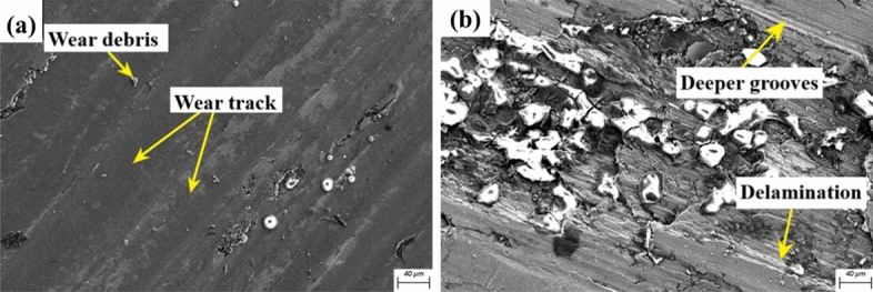
Worn surface morphology of composites at (a) 10N and (b) 40N.
Figure 16.

EDS evaluation of composite outer layer at 40 N applied load.
Influence of distance of sliding on the wear response
The RSM model generated for distance (Fig. 14b,c) revealed a wear response similar to that observed under varying loads, indicating the significant influence of sliding distance as an extrinsic wear parameter on the material loss next to load. However, the material loss rate was relatively lower compared to load variation, attributed to the resistance offered by hard ceramic reinforcing particles (SiC and TiS2) against surface layer disintegration and deformation. Wear rate increased linearly with distance values, with surface interaction pressure and sliding duration defining wear regimes. Lower surface interaction pressure at shorter distances (500 m) resulted in minimal surface deformation, while increased contact duration at longer distances led to elevated wear rates due to the rising contact stresses and temperature, causing plastic deformation and higher material removal rates. However, the marginally lower rate observed under varying distances depended on factors such as particle concentration, intermetallic attraction forces and reinforcing particle hardness. Worn morphology analysis at varying distances revealed a transition in wear regimes from mild to severe wear regimes. FE-SEM images (Fig. 17a) of the specimen at an initial sliding distance of 500 m showed visible hard ceramic particles contributing to material loss, with micro-cracking and micro-abrasive wear sub-regimes evident. Subsequent image (Fig. 17b) displayed increased wear rates at 2000 m, with numerous delamination and oxide layer sites indicative of adhesion wear regime effects, characterized by rolled-up layers and sparse wear debris particles. At longer sliding distances, wear rates peaked, accompanied by reinforcement particle pull-out owing to prolonged sliding time, leading to shearing of layers delamination sites58,59. EDS spectrum analysis (Fig. 18) at 2000 m confirmed the presence of oxide layer sites, with debris particles primarily comprising oxides and carbide particles, along with elements such as Fe, Cu, and Mg. Additionally, a fresher layer of exposed reinforcing particles contributing to increased wear rates and undergoing oxidation was visible on the specimen surface.
Figure 17.
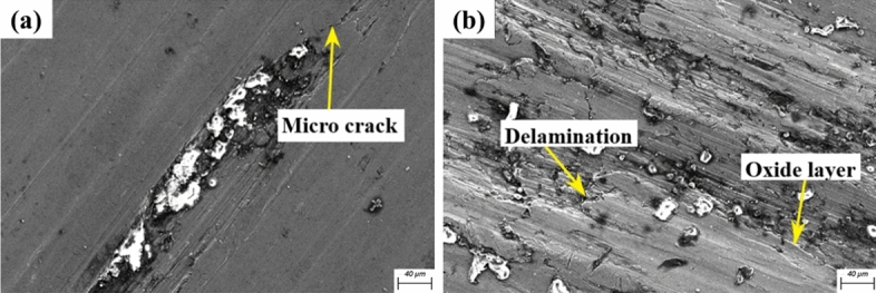
Worn surface morphology FE-SEM images at varying distances of (a) 500 m and (b) 2000 m.
Figure 18.

EDS evaluation of hybrid composite at 2000 m sliding distance.
Influence of sliding velocity on the wear response
The RSM surface plot for velocity (Fig. 14a,c) showed a higher wear rate with velocity increments, mirroring trends under varying distance and velocity conditions. This increase was due to higher interface temperatures, which weakened particle–matrix bonds, leading to permanent deformation at contact points and intense surface damage with debris formation60,61. The wear rate was minimal at low velocity with a constant load, but the prolonged experimental run increased interface temperature, softening the composite surface and oxidizing material layers, which formed a coating on the specimen62,63. At 4 m/s, tribolayer formation and oxidation rates rose, but the tribolayer had little time to reduce wear rate. Continuous contact forces fractured hard reinforcement particles, removing the tribolayer from the specimen pin. Studies show that the mechanically mixed layer (MML) is stable only at low loads and velocities26,64. Thus, the MML formed was unstable and quickly broke down, failing to significantly affect wear rate. The wear rate variation from mild to moderate was observed in the FE-SEM analysis. The worn surface displayed peeled-off tribo-layers, dislodged reinforcing particles, and delamination sites. A 1 m/s sliding velocity (Fig. 19a), features such as peeled-off layers, delamination sites, and exposed reinforcing particles indicated minor plastic deformation. Higher interface temperatures from prolonged contact time led to increased wear65. At 4 m/s (Fig. 19b), greater contact forces and higher interface temperature caused surface layer oxidation. Interaction of oxidized layers, reinforcing particles (SiC and TiS2), and wear debris, resulted in MML formation, with C and Fe particles from the stainless-steel counter disk detected due to abrasion by hard SiC particles, leading to Fe and C diffusion to the pin. Mapping and EDS studies at 4 m/s (Fig. 20) ensured the existence of C and Fe, with hard SiC particles visible on the specimen surface and Fe particles from the counter disk and TiS2 reinforcing particles dispersed within. The EDS spectrum’s high “O” concentration demonstrated the oxidized layers on the specimen’s surface.
Figure 19.

SEM images of worn surface at different velocities (a) 1 m/s, (b) 4 m/s.
Figure 20.

EDS evaluation of hybrid composite at 4 m/s of sliding distance.
Regression model studies under dry lubrication conditions:
The regression analysis studies were performed to confirm the precision of the statistical model developed through the RSM method. A linear regression model was created based on the factors' impacts on wear rate. It correlates the sliding distance, sliding speed and load. The regression equation of specific wear rate was described in Eq. (5).
| 5 |
where V, L are sliding velocity (m/s), and applied load (N). The coefficient sign associated with the wear parameter indicates the variation in the wear rate. The positive sign indicates an increasing effect on the wear rate by the process parameter. In contrast, a negative sign denotes a negative effect on the wear rate.
Optimization studies through the developed regression model:
The primary objective of the developed regression model was to reduce the material loss rate from the pin specimen and to identify the optimum process parameter combination at which the minimum wear parameter can be generated. Through this, a model that can create a minimum wear rate under real-world conditions can be developed. Through the RSM model and optimization studies, 7.22456E−05 mm3/Nm was determined as the desired minimum wear rate of the developed gradient composite. An optimum parameter combination of 10 N load, 1 m/s velocity and 500 m distance were determined, and the developed composite showed the minimum wear at these conditions. Figure 21 depicts the optimum parameter combination generated through RSM.
Figure 21.

Optimum parameters generated through RSM.
Dry sliding wear study was performed at the optimum condition generated through RSM, and the FE-SEM image worn surface of the pin specimen at an optimal condition of applied load (L) of 10 N, sliding distance (D) of 500 m, and sliding velocity (V) of 1 m/s is depicted in Fig. 22. Surface morphology studies revealed significant sliding track features such as grooves and microploughing zones. The fracturing of hard ceramic reinforcing particles caused surface layer abrasion and deep grooves, thereby exposing the fresher composite layers. The ploughed-out layers were evident as wear debris, demonstrating minimum wear.
Figure 22.
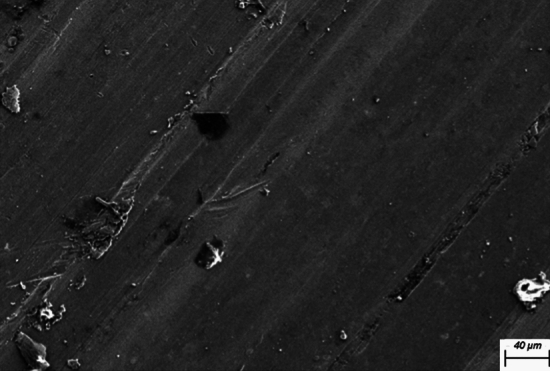
FE-SEM image of the specimen worn surface at the optimum condition of 10 N, 500 m, 1 m/s.
Conclusions
The hybrid functionally graded AlSi12Cu composite, incorporating 6 wt% SiC and 4 wt% TiS2 reinforcing particles, has been successfully developed to enhance mechanical and tribological studies.
Microstructural studies showed the highest distribution of reinforcement particles in the outer layers, corroborated by FE-SEM studies confirming a gradient distribution with minor particle clusters due to wetting. Additionally, EBSD studies highlighted the contribution of Ti to grain refinement.
Mechanical testing revealed a significant improvement in Brinell hardness and tensile strength, with a 31% and 69% increase respectively, in the outer layers compared to the inner layers. Superior mechanical properties were observed in the particle-rich layers under load application.
Fracture studies showed a mixed mode of failure (brittle and ductile) owing to particle clusters and particle-devoid zones.
Wear behaviour through pin-on-disk tribometer indicated increased material loss with higher loads, distances and velocities.
Worn morphology analysis revealed varying wear sub-regimes and more severe material loss under varying loads. The formation of a protective layer leads to minimum wear rate for the varying velocity.
Overall, this developed gradient composite exhibits promising characteristics for application of brake pads and clutch facings in automotive, bearings and bushings in aerospace industry, cutting tools, machining parts, pistons and cylinder liners where high resistance to wear and tear are critical.
Author contributions
N. Radhika, R. Jojith, S. Vignesh, H.S. Raghavenderen, S. Abinav wrote the main manuscript text and N. Radhika, R. Jojith, S. Vignesh, H.S. Raghavenderen, S. Abinav Adediran Adeolu Adesoji prepared figures. All authors reviewed the manuscript.
Data availability
The datasets used and analyzed during the current study available from the corresponding author on reasonable request.
Competing interests
The authors declare no competing interests.
Footnotes
Publisher's note
Springer Nature remains neutral with regard to jurisdictional claims in published maps and institutional affiliations.
Contributor Information
N. Radhika, Email: n_radhika1@cb.amrita.edu
Adeolu Adesoji Adediran, Email: dladesoji@gmail.com.
References
- 1.Ravikumar, M., Reddappa, H. N. & Suresh, R. Aluminium Composites fabrication technique and effect of improvement in their mechanical properties: A review. Mater. Today Proc.5, 23796–23805 (2018). 10.1016/j.matpr.2018.10.171 [DOI] [Google Scholar]
- 2.Jojith, R., Radhika, N. & Saleh, B. Metallographic, mechanical and reciprocating wear characterization and behavioural studies of untreated and T6 treated Al2O3/Al7Si0.3Mg functional composite material. Tribol. Int.174, 107693 (2022). 10.1016/j.triboint.2022.107693 [DOI] [Google Scholar]
- 3.Saleh, B. et al. Review on the influence of different reinforcements on the microstructure and wear behavior of functionally graded aluminum matrix composites by centrifugal casting. MMI26, 933–960 (2019). [Google Scholar]
- 4.Udupa, G., Rao, S. S. & Gangadharan, K. V. Functionally graded composite materials: An overview. Procedia Mater. Sci.5, 1291–1299 (2014). 10.1016/j.mspro.2014.07.442 [DOI] [Google Scholar]
- 5.Shao, L. et al. Effect of cold-spray parameters on surface roughness, thickness and adhesion of copper-based composite coating on aluminum alloy 6061 T6 substrate. Processes11(3), 959 (2023). 10.3390/pr11030959 [DOI] [Google Scholar]
- 6.Moustafa, E. B., Melaibari, A., Alsoruji, G., Khalil, A. M. & Mosleh, A. O. Tribological and mechanical characteristics of AA5083 alloy reinforced by hybridising heavy ceramic particles Ta2C & VC with light GNP and Al2O3 nanoparticles. Ceram. Int.48, 4710–4721 (2022). 10.1016/j.ceramint.2021.11.007 [DOI] [Google Scholar]
- 7.Ji, R. et al. Study on high wear resistance surface texture of electrical discharge machining based on a new water-in-oil working fluid. Tribol. Int.180, 108218 (2023).
- 8.El-Galy, I. M., Saleh, B. I. & Ahmed, M. H. Functionally graded materials classifications and development trends from industrial point of view. SN Appl. Sci.1, 1–23 (2019). 10.1007/s42452-019-1413-4 [DOI] [Google Scholar]
- 9.Vanam, J. P., Chiranjeevi, R., Kumar, R. S., Ramana, V. V. & Kumar, A. S. Effect of SiC on Mechanical, Microstructure and Tribological properties of Aluminum MMC processed by Stir Casting. IOP Conf. Ser. Mater. Sci. Eng.455, 012017 (2018). 10.1088/1757-899X/455/1/012017 [DOI] [Google Scholar]
- 10.Ambigai, R. & Prabhu, S. Analyzing the mechanical properties and characterization of aluminium (ADC-14) based functionally graded materials (FGM). Silicon14, 2839–2850 (2022). 10.1007/s12633-021-01050-2 [DOI] [Google Scholar]
- 11.El-Galy, I. M., Ahmed, M. H. & Bassiouny, B. I. Characterization of functionally graded Al-SiCp metal matrix composites manufactured by centrifugal casting. Alex. Eng. J.56, 371–381 (2017). 10.1016/j.aej.2017.03.009 [DOI] [Google Scholar]
- 12.Surya, M. S. & Prasanthi, G. Tribological behaviour of aluminum silicon carbide functionally graded material. Tribol. Ind.40, 247–253 (2018). 10.24874/ti.2018.40.02.08 [DOI] [Google Scholar]
- 13.Maurya, M., Maurya, N. K. & Bajpai, V. Effect of SiC reinforced particle parameters in the development of aluminium based metal matrix composite. Evergreen6, 200–206 (2019). 10.5109/2349295 [DOI] [Google Scholar]
- 14.Mishra, A. K. & Srivastava, R. K. Wear behaviour of Al-6061/SiC metal matrix composites. J. Inst. Eng. Ser. C98, 97–103 (2017). 10.1007/s40032-016-0284-3 [DOI] [Google Scholar]
- 15.Kumar, K., Dabade, B. M. & Wankhade, L. N. Experimental investigation and parameters optimization for better wear performance at elevated temperature of aluminium composites using RSM and GRA. Int. J. Interact. Des. Manuf.18, 2559–2569 (2024). 10.1007/s12008-022-00899-w [DOI] [Google Scholar]
- 16.Stojanović, B., Gajević, S., Kostić, N., Miladinović, S. & Vencl, A. Optimization of parameters that affect wear of A356/Al2O3 nanocomposites using RSM, ANN, GA and PSO methods. Ind. Lubr. Tribol.74, 350–359 (2022). 10.1108/ILT-07-2021-0262 [DOI] [Google Scholar]
- 17.Satpathy, A., Tripathy, S., Senapati, N. P. & Brahma, M. K. Optimization of EDM process parameters for AlSiC- 20% SiC reinforced metal matrix composite with multi response using TOPSIS. Mater. Today Proc.4, 3043–3052 (2017). 10.1016/j.matpr.2017.02.187 [DOI] [Google Scholar]
- 18.Ragunath, S., Radhika, N., Krishna, S. A. & Rajeshkumar, L. A study on microstructural, mechanical properties and optimization of wear behavior of friction stir processed AlCrCoFeNi High Entropy Alloy reinforced SS410 using response surface methodology. Heliyon10, e24429 (2024). 10.1016/j.heliyon.2024.e24429 [DOI] [PMC free article] [PubMed] [Google Scholar] [Retracted]
- 19.Kumar, R. & Dhiman, S. A study of sliding wear behaviors of Al-7075 alloy and Al-7075 hybrid composite by response surface methodology analysis. Mater. Des.50, 351–359 (2013). 10.1016/j.matdes.2013.02.038 [DOI] [Google Scholar]
- 20.Singh, G., Goyal, S., Miranda, G. & Sharma, N. Parametric study of the dry sliding wear behaviour of AA6082-T6/SiC and AA6082-T6/B4C composites using RSM. J. Mech. Sci. Technol.32, 579–592 (2018). 10.1007/s12206-018-0105-5 [DOI] [Google Scholar]
- 21.Kumar, K., Dabade, B. M., Wankhade, L. N., Agrawal, E. & Chavhan, G. Experimental investigation on tribological performance and development of wear prediction equation of aluminium composite at elevated temperatures. Int. J. Interact. Des. Manuf.18, 1979–1987 (2024). 10.1007/s12008-022-00911-3 [DOI] [Google Scholar]
- 22.Kanthavel, K., Sumesh, K. R. & Saravanakumar, P. Study of tribological properties on Al/Al2O3/MoS2 hybrid composite processed by powder metallurgy. Alex. Eng. J.55, 13–17 (2016). 10.1016/j.aej.2016.01.024 [DOI] [Google Scholar]
- 23.Wang, K., Zhang, Z. M., Yu, T., He, N. J. & Zhu, Z. Z. The transfer behavior in centrifugal casting of SiCp/Al composites. J. Mater. Process. Technol.242, 60–67 (2017). 10.1016/j.jmatprotec.2016.11.019 [DOI] [Google Scholar]
- 24.Heidary, D. S. B. & Akhlaghi, F. Theoretical and experimental study on settling of SiC particles in composite slurries of aluminum A356/SiC. Acta Mater.59, 4556–4568 (2011). 10.1016/j.actamat.2011.03.077 [DOI] [Google Scholar]
- 25.Sliding Wear Behavior of Particulate Reinforced Aluminium Metal Matrix Composites. https://www.researchgate.net/publication/342201848_Sliding_Wear_Behavior_of_Particulate_Reinforced_Aluminium_Metal_Matrix_Composites.
- 26.Moharrami, A., Razaghian, A., Emamy, M. & Taghiabadi, R. Effect of tool pin profile on the microstructure and tribological properties of friction stir processed Al-20 wt% Mg2Si composite. J. Tribol.141, 672 (2019). 10.1115/1.4044672 [DOI] [Google Scholar]
- 27.Dinaharan, I., Balakrishnan, M., David Rajaelvam, J. & Akinlabi, E. T. Microstructural characterization and tensile behavior of friction stir processed AA6061/Al2Cu cast aluminum matrix composites. J. Alloys Compd.781, 270–279 (2019). 10.1016/j.jallcom.2018.12.091 [DOI] [Google Scholar]
- 28.Zheng, Y. et al. Effects of Cu content and Cu/Mg ratio on the microstructure and mechanical properties of Al–Si–Cu–Mg alloys. J. Alloys Compd.649, 291–296 (2015). 10.1016/j.jallcom.2015.07.090 [DOI] [Google Scholar]
- 29.Vijaya Kumar, P., Jebakani, D., Velmurugan, C. & Senthilkumar, V. Effect of SiC on mechanical and microstructural characteristics of Al based functionally graded material. Silicon14, 1247–1252 (2022). 10.1007/s12633-020-00933-0 [DOI] [Google Scholar]
- 30.Fathi, R., Ma, A., Saleh, B., Xu, Q. & Jiang, J. Investigation on mechanical properties and wear performance of functionally graded AZ91-SiCp composites via centrifugal casting. Mater. Today Commun.24, 101169 (2020). 10.1016/j.mtcomm.2020.101169 [DOI] [Google Scholar]
- 31.Prabhu, T. R. Processing and properties evaluation of functionally continuous graded 7075 Al alloy/SiC composites. Arch. Civ. Mech. Eng.17, 20–31 (2017). 10.1016/j.acme.2016.08.004 [DOI] [Google Scholar]
- 32.Singh, G., Chan, S. L. I. & Sharma, N. Parametric study on the dry sliding wear behaviour of AA6082–T6/TiB2 in situ composites using response surface methodology. J. Braz. Soc. Mech. Sci. Eng.40, 1–12 (2018). 10.1007/s40430-018-1235-0 [DOI] [Google Scholar]
- 33.Hadadzadeh, A. et al. Microstructural investigation and mechanical behavior of a two-material component fabricated through selective laser melting of AlSi10Mg on an Al-Cu-Ni-Fe-Mg cast alloy substrate. Addit. Manuf.31, 100937 (2020). [Google Scholar]
- 34.Pk, J. et al. The effect of SiC content in aluminum-based metal matrix composites on the microstructure and mechanical properties of welded joints. J. Mater. Res. Technol.12, 2325–2339 (2021). 10.1016/j.jmrt.2021.04.015 [DOI] [Google Scholar]
- 35.Borkar, H., Seifeddine, S. & Jarfors, A. E. W. In-situ EBSD study of deformation behavior of Al–Si–Cu alloys during tensile testing. Mater. Des.84, 36–47 (2015). 10.1016/j.matdes.2015.06.100 [DOI] [Google Scholar]
- 36.Moustafa, E. B. & Mosleh, A. O. Effect of (Ti–B) modifier elements and FSP on 5052 aluminum alloy. J. Alloys Compd.823, 153745 (2020). 10.1016/j.jallcom.2020.153745 [DOI] [Google Scholar]
- 37.Heiberg, G. & Arnberg, L. Investigation of the microstructure of the Al–Si eutectic in binary aluminium–7 wt% silicon alloys by electron backscatter diffraction (EBSD). J. Light Metals1, 43–49 (2001). 10.1016/S1471-5317(00)00005-5 [DOI] [Google Scholar]
- 38.Fan, K. L., Liu, X. S., He, G. Q. & Chen, H. Elevated temperature low cycle fatigue of a gravity casting Al–Si–Cu alloy used for engine cylinder heads. Mater. Sci. Eng. A632, 127–136 (2015). 10.1016/j.msea.2015.02.069 [DOI] [Google Scholar]
- 39.Daniel, A. A., Murugesan, S., Manojkumar, M. & Sukkasamy, S. Dry sliding wear behaviour of aluminium 5059/SiC/MoS2 hybrid metal matrix composites. Mater. Res.20, 1697–1706 (2017). 10.1590/1980-5373-mr-2017-0009 [DOI] [Google Scholar]
- 40.Asadi, P., Givi, M. K. B., Abrinia, K., Taherishargh, M. & Salekrostam, R. Effects of SiC particle size and process parameters on the microstructure and hardness of AZ91/SiC composite layer fabricated by FSP. J. Mater. Eng. Perform.20, 1554–1562 (2011). 10.1007/s11665-011-9855-x [DOI] [Google Scholar]
- 41.Nithesh, K., Gowrishankar, M. C., Nayak, R. & Sharma, S. Effect of light weight reinforcement and heat treatment process parameters on morphological and wear aspects of hypoeutectic Al-Si based composites: A critical review. J. Mater. Res. Technol.15, 4272–4292 (2021). 10.1016/j.jmrt.2021.10.019 [DOI] [Google Scholar]
- 42.Gao, S., Li, H., Huang, H., & Kang, R. Grinding and lapping induced surface integrity of silicon wafers and its effect on chemical mechanical polishing. Appl. Surf. Sci.599, 153982 (2022).
- 43.Zhao, Y., Jing, J., Chen, L., Xu, F. & Hou, H. Current research status of interface of ceramic-metal laminated composite material for armor protection. Acta. Metall. Sin.57(9), 1107–1125 (2021). [Google Scholar]
- 44.Rebba, B. & Ramanaiah, N. Evaluation of mechanical properties of aluminium alloy (Al-2024) reinforced with molybdenum disulphide (MOS2) metal matrix composites. Procedia Mater. Sci.6, 1161–1169 (2014). 10.1016/j.mspro.2014.07.189 [DOI] [Google Scholar]
- 45.Jojith, R. & Radhika, N. Heat-treatment studies on mechanical and reciprocating wear behaviour of functionally graded A356 alloy. Mater. Res. Express6, 1165 (2019). 10.1088/2053-1591/ab4dd7 [DOI] [Google Scholar]
- 46.Cheng, S. L., Yang, G. C., Zhu, M., Wang, J. C. & Zhou, Y. H. Mechanical properties and fracture mechanisms of aluminum matrix composites reinforced by Al9(Co, Ni)2 intermetallics. Trans. Nonferrous Metals Soc. China20, 572–576 (2010). 10.1016/S1003-6326(09)60180-1 [DOI] [Google Scholar]
- 47.Yadav, P. K. et al. Effect of eutectic silicon and silicon carbide particles on high stress scratching wear of aluminium composite for various testing parameters. Wear482–483, 203921 (2021). 10.1016/j.wear.2021.203921 [DOI] [Google Scholar]
- 48.Moharami, A. & Qodosi, P. Enhanced dry sliding friction and wear behaviors of Mg–Mg2Si composites. Compos. Commun.36, 101365 (2022). 10.1016/j.coco.2022.101365 [DOI] [Google Scholar]
- 49.Bharath, V. et al. Microstructural evolution, tensile failure, fatigue behavior and wear properties of Al2O3 reinforced Al2014 alloy T6 heat treated metal composites. Materials15, 4244 (2022). 10.3390/ma15124244 [DOI] [PMC free article] [PubMed] [Google Scholar]
- 50.Moazami, M. R., Razaghian, A., Mirzadeh, H., Emamy, M. & Moharami, A. Tribological behavior of as-cast and wrought Al–Mg2Si hybrid composites reinforced by Ti-based intermetallics. J. Mater. Res. Technol.20, 1315–1327 (2022). 10.1016/j.jmrt.2022.07.142 [DOI] [Google Scholar]
- 51.Bai, C. et al. Effect of different Mg2Si concentrations on the wear properties and microstructure of Mg2Si/Al–5 wt.% Cu Composites. Int. J. Metalcast. (2021).
- 52.Ayyanar, S., Gnanavelbabu, A., Rajkumar, K. & Loganathan, P. Studies on high temperature wear and friction behaviour of AA6061/B4C/hBN hybrid composites. Metals Mater. Int.27, 3040–3057 (2021). 10.1007/s12540-020-00710-z [DOI] [Google Scholar]
- 53.Ragunath, S., Radhika, N., Aravind Krishna, S. & Jeyaprakash, N. Enhancing microstructural, mechanical and tribological behaviour of AlSiBeTiV high entropy alloy reinforced SS410 through friction stir processing. Tribol. Int.188, 108840 (2023). 10.1016/j.triboint.2023.108840 [DOI] [Google Scholar]
- 54.Reddy, T. P., Kishore, S. J., Theja, P. C. & Rao, P. P. Development and wear behavior investigation on aluminum-7075/B4C/fly ash metal matrix composites. Adv. Compos. Hybrid Mater.3, 255–265 (2020). 10.1007/s42114-020-00145-5 [DOI] [Google Scholar]
- 55.Radhika, N. & Raghu, R. Study on three-body abrasive wear behavior of functionally graded Al/TiB2 composite using response surface methodology. Part. Sci. Technol.36, 816–823 (2018). 10.1080/02726351.2017.1305024 [DOI] [Google Scholar]
- 56.Khare, M., Gupta, R. K. & Bhardwaj, B. Dry sliding wear behaviour of Al 7075/Al2O3/B4C composites using mathematical modelling and statistical analysis. Mater. Res. Express6, 126512 (2019). 10.1088/2053-1591/ab546a [DOI] [Google Scholar]
- 57.Cui, G., Li, S., Liu, H. & Gao, G. Effect of carbon on the microstructure and sliding wear performance of CoCrMo matrix composites from room temperature to 1000 °C. J. Mater. Res. Technol.8, 4778–4787 (2019). 10.1016/j.jmrt.2019.08.024 [DOI] [Google Scholar]
- 58.Radhika, N. & Raghu, R. Development of functionally graded aluminium composites using centrifugal casting and influence of reinforcements on mechanical and wear properties. Trans. Nonferrous Metals Soc. China26, 905–916 (2016). 10.1016/S1003-6326(16)64185-7 [DOI] [Google Scholar]
- 59.Moharrami, A. et al. Enhancing the mechanical and tribological properties of Mg2Si-rich aluminum alloys by multi-pass friction stir processing. Mater. Chem. Phys.250, 123066 (2020). 10.1016/j.matchemphys.2020.123066 [DOI] [Google Scholar]
- 60.Ravindranath, B. S., Murthy, B. R. N., Ramu, H. C. & Nambiar, S. S. Process parameters optimization of pin and disc wear test to minimize the wear loss of general-purpose aluminium grades by taguchi and simulation through response surface methodology. Eng. Sci.16, 366–373 (2021). [Google Scholar]
- 61.Sharma, A., Belokar, R. M. & Kumar, S. Dry sliding wear characterization of red mud reinforced aluminium composite. J. Braz. Soc. Mech. Sci. Eng.40, 1–12 (2018). 10.1007/s40430-018-1223-4 [DOI] [Google Scholar]
- 62.Rathod, H. et al. Friction and sliding wear studies on functionally graded Al LM25/WC composite. IOP Conf. Ser. Mater. Sci. Eng.577, 012159 (2019). 10.1088/1757-899X/577/1/012159 [DOI] [Google Scholar]
- 63.Baradeswaran, A., Vettivel, S. C., Elaya Perumal, A., Selvakumar, N. & Franklin Issac, R. Experimental investigation on mechanical behaviour, modelling and optimization of wear parameters of B4C and graphite reinforced aluminium hybrid composites. Mater. Des.63, 620–632 (2014). 10.1016/j.matdes.2014.06.054 [DOI] [Google Scholar]
- 64.Radhika, N. & Raghu, R. Dry sliding wear behaviour of aluminium Al-Si12Cu/TiB2 metal matrix composite using response surface methodology. Tribol. Lett.59, 1–9 (2015). 10.1007/s11249-015-0516-3 [DOI] [Google Scholar]
- 65.Radhika, N., Krishna, S. A., Basak, A. K. & Adediran, A. A. Microstructure and tribological behaviour of CoCrCuFeTi high entropy alloy reinforced SS304 through friction stir processing. Sci. Rep.14, 1–14 (2024). 10.1038/s41598-024-54267-7 [DOI] [PMC free article] [PubMed] [Google Scholar]
Associated Data
This section collects any data citations, data availability statements, or supplementary materials included in this article.
Data Availability Statement
The datasets used and analyzed during the current study available from the corresponding author on reasonable request.