Abstract
Manual navigation of a guidewire is the first step in endovascular interventions. However, this procedure is time consuming with uncertain results due to tortuous vascular anatomy. This paper introduces the design of a novel COaxially Aligned STeerable (COAST) guidewire robot that is 0.40 mm in diameter demonstrating variable curvature and independently controlled bending length of the distal end. The COAST design involves three coaxially aligned tubes with a single tendon running centrally through the length of robot. The outer tubes are made from micromachined nitinol allowing for tendon-driven bending of the robot at various segments of the robot, thereby enabling variable bending curvatures, while an inner stainless steel tube controls the bending length of the robot. By varying relative positions of the tubes and the tendon by insertion and retraction in the entire assembly, various joint lengths and curvatures can be achieved, which enables a follow-the-leader motion. We model the kinematics, statics, as well as the coupling within tubes of the COAST robot and develop a simple controller to control the distal tip of the robot. Finally, we experimentally demonstrate the ability of COAST guidewire to accurately navigate through phantom anatomical bifurcations and tortuous anatomy.
Keywords: Surgical Robotics, Steerable Catheters/Needles, Medical Robots and Systems, Mechanism Design
I. Introduction
CARDIOVASCULAR diseases (CVDs) such as chronic heart disease, stroke, or high blood pressure are among the top ten leading causes of death in the US, resulting in direct and indirect costs of about $330 billion in 2014 [1]. The minimally invasive treatment of most CVDs begins with the clinician inserting a guidewire from a suitable location in the patient’s vasculature and navigating it to the blocked (or diseased) blood vessel. The guidewire is a passive wire, typically made of nitinol, with a diameter of 0.3556 mm - 0.889 mm (typical wires are in the range of 0.3556 mm - 0.4572 mm or commonly referred to as the 0.014” to 0.018” guidewire) and a length of 50 cm - 260 cm depending on intervention paths. Once the guidewire is navigated to the blocked vasculature, the clinician can use the wire as a carrier for a variety of catheters that help to clear the blockage. Navigation of the guidewire remains largely manual, with proximal insertion, retraction, and rotation being the only degrees-of-freedom (DoFs) available to the clinician to control the distal tip. However, angulation, vessel tortuosity, or calcification of the blood vessel can make this control challenging [2], [3], and can result in kinking and breakage of the guidewire [4]. One solution may be changing the wire to alternative guidewire with a different stiffness/curvature [5], [6], but this requires multiple sets of guidewire and the repeated replacement can cause vascular trauma. These challenges in the manual navigation result in increased procedure times and radiation exposure [7], [8] for the patient, clinician, and the operating room staff.
In previous work, steerable guidewires and micro-catheters have been proposed; however, due to the size constraints on the wire diameter, a majority of these are actuated externally using a magnetic source [9], [10] or are tendon driven [11], [12]. The bulky setup required for magnetic actuation may interfere with imaging modalities such as fluoroscopy and magnetic resonance imaging (MRI). Tendon driven designs have fixed joint lengths and do not perform any sort of follow-the-leader motion making it difficult for these wires to navigate into tortuous anatomical paths. To implement the follow-the-leader motion, an extensible bending section design [13] has been applied for tendon-driven continuum robots. However, its limited range of extensible length makes it difficult to achieve the ideal follow-the-leader motion and its dimension/complexity cannot be feasible for the guidewire application. Mechanisms such as concentric tube assemblies allow the curvature and bending angle of the robot to be varied with increasing joint length [14], but suffer from complex modeling and instabilities arising from the presence of multiple minimum energy states resulting in the robot ‘snapping’ from one minimum energy state to another during operation [15]. The authors in [16]–[18] suggest a way to avoid these problems by introducing notch structures within the individual tubes. However, in all designs, coupling between the joint lengths and bending angle of the robot is retained, i.e. the bending length and the bending angle of these robots cannot be individually controlled.
In this work, we propose a tendon-driven ‘COaxially Aligned STeerable (COAST)’ guidewire robot that can simultaneously and independently control the bending angle and the length of the bending segment, thereby executing ‘follow-the-leader’ motion at its distal bending segment. Finally, the entire robot assembly can be miniaturized to a total outer diameter of 0.40 mm. These characteristics make the COAST mechanism extremely suitable for use as a micro-scale steerable robotic guidewire. The guidewire is capable of advancing its distal end through complex vasculature of varying curvatures with minimal interaction and support from the vessel walls. Therefore, the proposed study can implement a vascular intervention procedure with a single COAST guidewire navigation without any replacement to alternative guidewires, which may significantly reduce the operational time and effort. We first introduce the mechanism of the robot along with the design and assembly process of the coaxial tubes in Section II. We analyze the kinematic model of the robot’s curvature and the tendon stroke for the tendon controlling the robot in Section III-A, followed by a static model of the robot and coupling analysis in Section III-B. Section IV describes a control strategy used to navigate the robot through the vasculature of various curvatures followed by an experimental demonstration of the same in a phantom vasculature (see Section IV-B).
II. Mechanism and Design
To implement the ‘follow-the-leader’ motion with limited DoFs in the compact space required for a guidewire, the COAST robot has coaxially aligned three layered structure consisting of inner, middle, and outer tubes (see Fig. 1(a)). The inner tube is made of stainless steel and has a regular cylindrical cross-section with an inner channel, while the middle and outer tubes are nitinol tubes with notch patterns micromachined along the lengths of each tube. These notches are unidirectional asymmetric notch joints such as the ones proposed in [19], [20]. Each of the tubes has suitable dimensions so that they can respectively slide within each other. To avoid collision/interference between the notches on the middle and outer tube, there is a 180 degree phase difference in the notches. A tendon passes through the inner tube and is connected to the distal end of the middle tube. Depending on the relative positions of each tube and notch pattern, the proposed structure is divided into three segments (i.e., segments 1-3 in Fig 1(a)). In segment 1, the notch pattern on the middle tube decreases its second moment of area and shifts its neutral axis to the un-notched side, which increases compliance as well as the moment arm of the tendon. In segment 2, however, introducing the stainless steel inner tube increases the second moment of area of the combined structure, resulting in a significant increase in the stiffness of segment 2 as well as decrease of the moment arm. Lastly, only the outer tube retains its notch patterns in segment 3, which contributes to an increased stiffness of segment 3. Therefore, the proposed structure has three segments with varying stiffness and can be largely classified into bending (i.e., segment 1) and non-bending segments (i.e., segments 2 and 3) depending on the relative position of the inner tube.
Fig. 1:
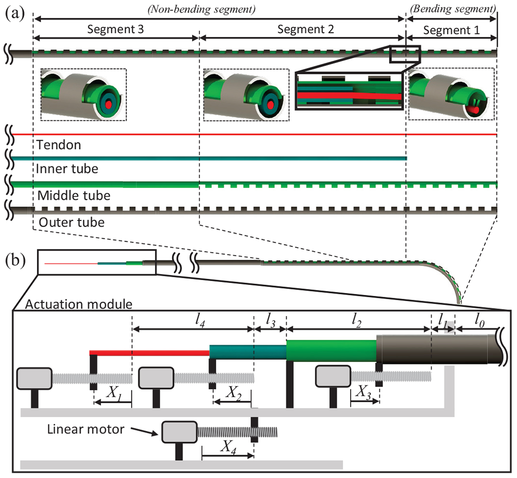
(a) Schematic of the coaxially aligned steerable (COAST) guidewire robot with the various tubes used in the assembly, (b) Schematic of the actuation module used to control the tendon and coaxial tubes.
The proposed coaxially aligned tubes and tendon are connected to an actuation module (see Fig. 1(b)). The tendon, inner tube, and outer tube, are connected to linear motors respectively, while the middle tube is fixed to the actuation module itself. Therefore, the actuation module has four control variables: , and , corresponding to tendon stroke, relative distance between the inner and middle tubes, displacement of the outer tube, and displacement of the actuation module respectively.
Given the control variables, the proposed mechanism can form the shape of any arc within geometric constraints, since and control the curvature and arc length of bending segment, respectively (see Fig. 2(a) - details are introduced in Section III). Therefore, the bending segment can follow the curved path of the vasculature, which is a function of the curvature and arc length by controlling and as well as feeding the actuation module , which leads to a follow-the-leader motion during guidance along a curved path (see Fig. 2(b)) without any passive support from the vasculature wall. Finally, the outer tube can slide and proceed further along the curved middle tube (see Fig. 2(c)); It can provide a stable passage for the middle tube to reach proper locations as an introducer sheath, while retaining the curvature at the location of the curved path. This entire procedure can then be repeated at the next curved path to reach the final target location. The proposed mechanism therefore provides easy insertion of the guidewire into tortuous vasculature without replacement of guidewire, thereby significantly reducing the procedure time.
Fig. 2:
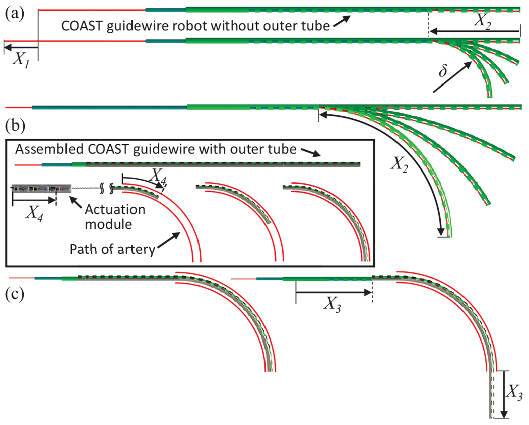
(a) Controlling the tendon stroke and joint length allows for variable curvature, (b) Controlling and while advancing the actuation module allows for follow-the-leader motion, (c) outer tube advanced individually to go further into a target vasculature, while retaining the curvature at the location of the vessel tortuosity.
The proposed COAST guidewire was constructed and assembled as shown in Fig. 3. The outer and middle tubes are made using superelastic nitinol for high bending capability and their notch patterns are fabricated on a femtosecond laser (WS-Flex Ultra-Short Pulse Laser Workstation, Optec, Frameries, Belgium). The tendon is also made of nitinol for ease of insertion through the tubes and ease of attachment. Finally the inner tube is stainless steel, since it has a higher stiffness than nitinol. The outer tube, the inner tube, and the tendon are connected to linear motors (Maxon Precision Motors, MA, United States, resolution ) and generate linear motion, sliding on each surface (see Fig. 3(c)). Through the motor strokes, we can control the tendon displacement and the bending joint length , thereby achieving variable curvatures at several bending joint lengths (see Fig. 3(b)). The entire actuation stage is installed on the base stage with a linear guide and actuated by a base linear motor (to control ). The tendon is connected to a miniature force sensor [21] to measure the tendon tension. The dimensions of the tubes used in the prototype are summarized in Table I. In this paper, the prototype of the COAST guidewire was fabricated with a shorter length than that of conventional guidewires for in vitro feasibility test.
Fig. 3:
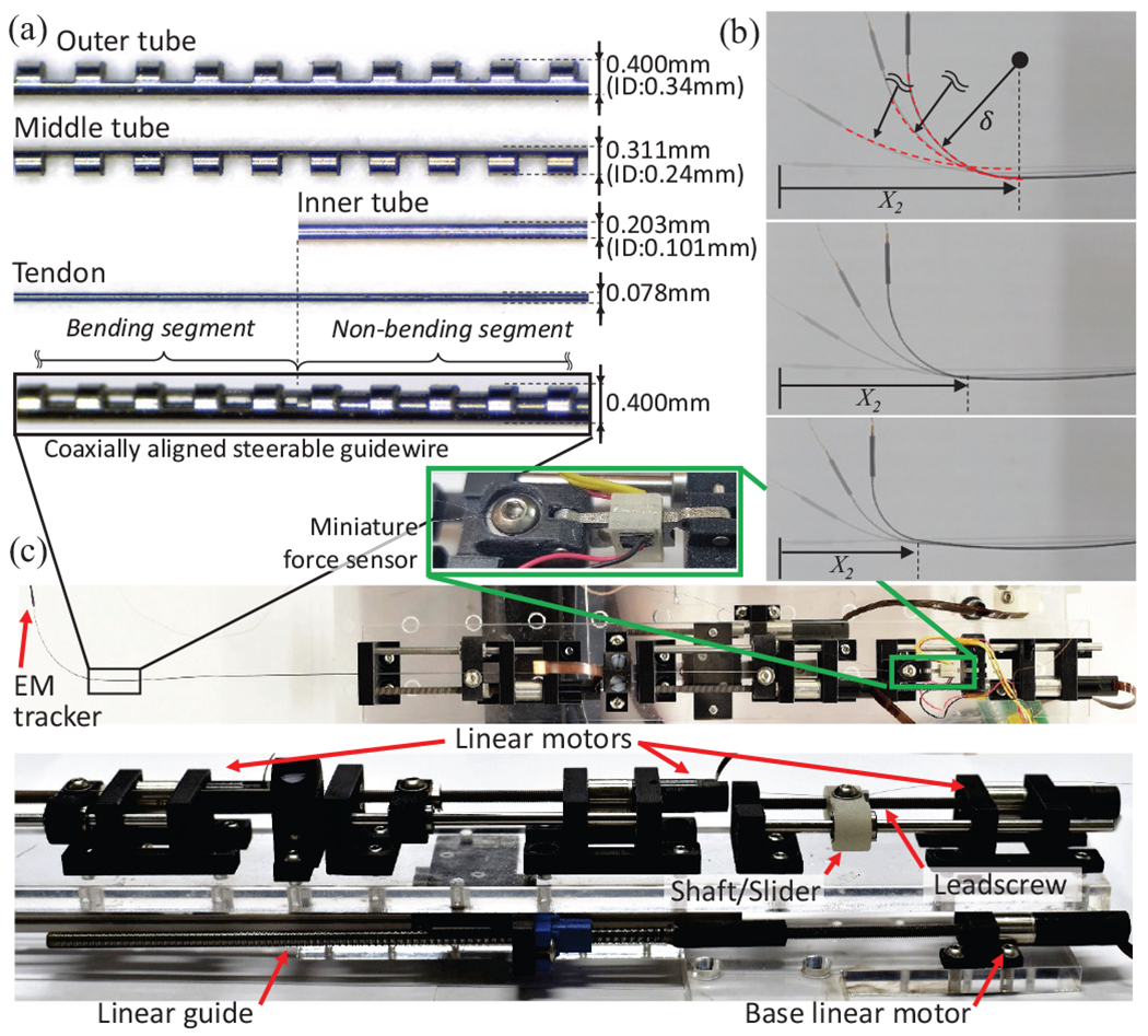
(a) Coaxial tubes and dimensions, (b), Demonstration of COAST achieving various curvatures at different arc lengths (c) Actuation stage showing individual linear motors to control the COAST guidewire.
TABLE I:
Specifications of the COAST guidewire prototype.
| Items | Outer tube | Middle tube | Inner tube | Tendon | |
|---|---|---|---|---|---|
| Total length | 188.4mm | 240.0mm | 256.6mm | 280.0mm | |
| Length of the notched section | 94.0mm | 57.0mm | - | - | |
| Outer diameter, | 0.400mm | 0.311mm | 0.203mm | 0.078mm | |
| Inner diameter, | 0.340mm | 0.240mm | 0.102mm | - | |
| d | 0.270mm | 0.249mm | - | - | |
| h | 0.3mm | 0.3mm | - | - | |
| c | 0.3mm | 0.3mm | - | - | |
| Young’s modulus | 77.3GPa | 77.3GPa | 200GPa | 53.965GPa | |
|
| |||||
| Items | l 0 | l 1 | l 2 | l 3 | l 4 |
| Dimension | 136.9mm | 14.0mm | 89.1mm | 16.5mm | 92.6mm |
III. Kinematic and Static Models
In this section, we derive the relationship between the tendon stroke , the desired curvature , and bending joint length . We also derive a static model for the bending portion of the guidewire and a model for the coupling in non-bending portions. We begin by considering the case of a single notched tube (either the outer or middle tube) with notch depth, , notch width, , and notches in the joint (see Fig. 4(a)). Furthermore, and are the outer and inner radii of the tube respectively and laser micromachining creates a cross-section of area at the notches (see Fig. 4(a)(inset)). This cross-section is expressed as a sector of area, , subtracted from a sector of area, , where is the central angle created by laser micromachining. To derive the kinematics of joint, we must first arrive at an expression for the neutral axis of the joint. As can be seen in Fig. 4(a), the neutral axis of the joint is shifted away from the central axis of the tube along the -axis, due to the notch pattern. The location of this axis for the outer circular sector with area, , is given as , and for the inner circular sector with area, , it is given as . Finally, the neutral axis of a composite structure such as our notch cross-section with area, , is given as follows:
| (1) |
Fig. 4:
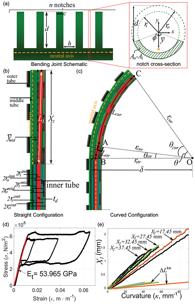
(a) Bending joint schematic and notch cross-section view, (b)-(c) The coaxial tube structure geometry in the straight configuration and with curvature , (d) Stress-strain curve for the Nitinol tendon, (e) relationship for several values of (black lines indicate the experimental value - colored lines indicate theoretical values).
Therefore, the location of the neutral axis of our notched tube is given as follows:
| (2) |
The second moment of area of the notched segment of area, , about the central axis of the tube is given by:
| (3) |
Now, from the parallel axis theorem and the Eq. (2), the second moment of area of the notched segment about the neutral axis of the tube is given by:
| (4) |
In Eqs. (2) and (4), the subscript represents either the outer, middle, or inner tubes.
A. Joint Kinematics
Given a desired curvature, , and the joint length, , the bending angle required is given by . A schematic of the bending portion of the robot along with the various lengths and radii of the tubes is shown in Fig. 4(b). The tendon diameter is indicated as . The initial length of the tendon in this straight configuration is given by . Here, , is the offset between the inner tube and the middle notch joint. This is the length at which the joint begins to bend and is therefore critical to eliminate any slacking of the tendon at any stage.
As the bending segment of the guidewire bends to a certain curvature , the inner wall of the middle tube forms an arc of angle with center ‘’ (see Fig. 4(c)). As a result, the path of the tendon through the middle tube can be divided into two portions. The straight portion of the tendon, denoted by line segment in Fig. 4(c), runs from the inner wall of the inner tube and intersects the bending portion of the middle tube at point ‘’ such that the line is tangential to the bending curve at point ‘’. The second portion, denoted by arc in Fig. 4(c), bends with the middle tube, running along the inner wall of the middle tube with radius, . Furthermore, (derived in Eq. (2) and abbreviated as in future references) is the location of the neutral axis of the notched section of the middle tube in its central coordinate frame. From geometry, we observe that the triangle formed by the straight portion of the tendon, , is a right angled triangle, where , and . Furthermore, is the radius of curvature of the middle joint and is the radius of the tendon cross-section. The length of the straight portion of the tendon is then given as . The interior angle between the sides and is given as and the length of the curved portion of the tendon is: . Finally, the tendon displacement needed for the target geometry combination of is given by . Furthermore, motor stroke, , is highly dominated by tendon elongation for any combination [22]. We therefore add an elongation term to our kinematics model as follows:
| (5) |
Here, the applied tendon tension is and is the un-elongated original length of the entire tendon from the tip of the robot to the actuator. is the Young’s modulus of the Nitinol tendon in its austenite phase and was experimentally derived (see Fig. 4(d)). To test our kinematics model, we evaluate for several joint length, , values (see Fig. 4(e)). For each experiment, the tendon tension, , was used to evaluate and account for tendon elongation. Motor stroke data from the encoder was used as the ground truth for each case. Finally, for each case, the kinematics term, , is also plotted. In each case, the tendon elongation dominates the joint kinematics. Furthermore, Eq. (5) correctly predicts the joint kinematics, especially for higher values of in Fig. 4(e), . We infer that the higher deviation from the model at lower values ( in Fig. 4(e), ) is due to higher friction losses as the joint stiffens with decreasing joint length.
B. Statics Model
Ideally, the design goal is that a tendon stroke of will result in a curvature, in the bending segment (see ‘segment 1’ in Fig. 1), while the non-bending segments (see ‘segment 2 and 3’ in Fig. 1) will not undergo any deformation. However, due to the arrangement of the coaxial tubes within the non-bending segment and the coupling between segments, these segments too undergo a small amount of deformation. In this section, we will develop and validate a statics model for segment 1 and a coupling model relating joint notch depths and coupling effects on the non-bending segments. Segment 1 (see inset in Fig. 5(a)) is composed of the middle and outer notched tubes, actuated by the tendon placed along the inner wall of the middle tube. Since the tendon is connected to the distal tip of the middle tube, a moment, , is applied to the entire structure. Here, the moment arm, is the displacement between the tendon and neutral axis of the middle tube in segment-n (see segments 1-3 in Fig. 5(a)). Furthermore, due to the actuation of the tendon, the middle tube gets displaced and touches the outer tube (see the cross-section of the Segment 2 in Fig. 5(a)). The moment arm of the tendon tension, , still remains constant. We assume that the bending of any of the notched tubes (middle or outer) occurs due to the accumulation of the bending segments at every notch along the tube. Since the number of notches in each joint is high for the middle and outer tubes respectively), for a single notched element of a tube, the curvature achieved by the bending element may therefore be considered negligible for a bend in the joint). Furthermore, in this work, we assume that the total bending angle is distributed uniformly across all the notches, while the segment of length, (see Fig.4(a)), between two notches does not undergo any bending. Assuming uniform notch spacing within a certain segment, we define: , to indicate the ratio of the width of an individual notch to the sum of notched and un-notched individual section of the joint. The notched and un-notched sections are uniformly repeated for the specific joint segment. Note that the middle and outer tube were designed with a same value of in this work. By applying the Euler beam equation for the relationship for the Segment 1, we obtain:
| (6) |
Fig. 5:
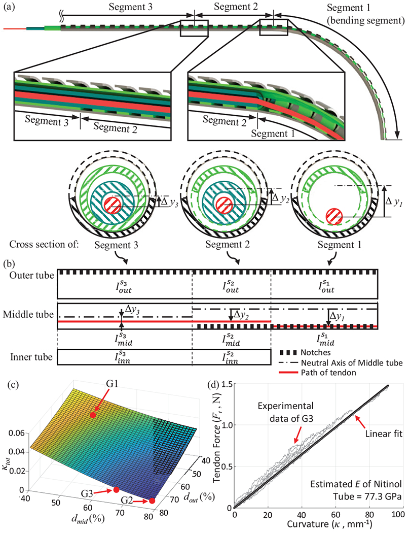
(a) Cross-sections of the three segments of the robot, (b) Schematic of each segment with inertia values. (c) The decoupling estimate, for various middle and outer tube depths (in terms of percentage of each tube’s outer diameter), (d) Experimental result for relationship.
Since the two tubes are not bonded together and are allowed to slide over each other, the resulting curvature, , occurs due to the sum of inertial terms in the above equation. In the above equation, a second moment of area of each tube for the Segment 1, , where , is defined in Eq. (4). For segment 2, the tendon is no longer located at the inner wall of the middle tube, but is located inside the inner tube (as seen in the cross-section view in Fig. 5(b)). This reduces the moment arm of the applied tendon tension to .
Furthermore, the addition of the inner tube in segment 2 adds an inertia term in the statics model (see Fig. 5(b)):
| (7) |
As mentioned previously, the inner tube is made of 304 stainless steel and therefore, we assume from manufacturer’s datasheet. Furthermore, the inner tube is not notched and therefore from Eq. (4). Since tendon tension stays constant throughout the length of the robot, we can substitute the value of from Eq. (6) in Eq. (7) to get the following coupling ratio between the curvatures of segments 1 and 2 (namely and ):
| (8) |
Similar to segment 2, segment 3 is composed of all three tubes. However, the key difference is that in this segment, the middle tube is not notched (see Fig. 5(c)). The moment arm of the applied tendon tension is reduced to and the coupling relationship between segment 1 and segment 3 is given as follows:
| (9) |
Here, is the moment of inertia of the un-notched middle tube and is defined in Eq. (4). From Eqs. (8) and (9), it is clear that the ratio of coupling between the bending and non-bending segments depends only on the geometry of the cross-section of the segments (and not their relative lengths). Therefore, are the only two parameters that can affect coupling. In this work, we have simply used a sum of the coupling ratios, as a cost function for optimization. Fig. 5(c) shows () vs. . The parameters () are denoted as a percentage of their corresponding outer diameters. As the depth of the micromachined notch increases, the extent of coupling between segments reduces. However, this decoupling is achieved at the expense of robot tip stiffness. We micromachined three samples corresponding to varying values of () (see Fig. 6). As expected, we find the highest coupling in ‘G1’ and negligible coupling in ‘G2’ (see Fig. 6). While joint ‘’ is sufficiently stiff for navigating vasculature but highly coupled, sample ‘G2’ is extremely compliant and can be used only in cases where a large curvature is required with minimal interaction with the walls of the blood vessels. As a result, for the purpose of this paper, we choose the joint ‘’ as the most likely candidate to achieve high curvatures with minimal coupling and high stiffness. Next, we validated our statics model for segment 1 (see Eq. (6)) for this sample ‘’. We actuated the COAST guidewire to reach several curvatures to obtain a relationship (see Fig. 5(d)). First, we must note that for a variety of curvatures and bending joint lengths (, the relationship stays constant and can be approximated for this geometry by a linear fit . Using this linear approximation and Eq. (6), and knowing the values for from the geometry of sample ‘’, we can estimate the elastic modulus of the assembly, , which is within the range of valid values for superelastic nitinol in the austenite phase.
Fig. 6:

Three samples with varying depths of middle and outer tubes demonstrate varying coupling between the bending and non-bending segments.
IV. Control and Experiment
A. Actuation and Control
From Eqs. (5) and (6), we derive a direct relationship between and with given as follows:
| (10) |
Therefore, can be directly controlled by without the need for any force information.
Based on Eq. 10 and the geometric information of the vessel, , (see Fig. 7), we can control the variables (i.e, , and ) to follow the specific path of the vasculature. It is assumed that of the vasculature can be identified by using non-invasive imaging observations such as fluoroscopy or MRI and the curve has a constant curvature. The intervention distance, , in the form of a path variable, along the central line of the vessel is fed into the kinematic/static model with and it generates references of -th linear actuators, . Then, , according to in each vascular section (i.e., P1, P2, or P3 in Fig. 7) is follows:
| (11) |
Fig. 7:

Control system for the COAST guidewire robot.
Fig. 8(a) shows coordinates of the tip following given reference curved paths with various curvatures by using the proposed control scheme in free space (here and are assumed to be 0) and were measured from the EM tracker in a single tracking trial. There are relatively small errors in low curvature paths (mean ), however, the error significantly increases in paths having high curvatures (mean ). We believe this mainly occurs from the coupling of segments 2 and 3 (identified and modeled in Section III-B) which shifts the coordinate of the Segment 1. However, it is to be noted that this robot is meant to be actuated in a constrained space and this coupling issue can be compensated in the constrained space like vasculature. The detailed compensation range will be identified along with a design optimization in a future in vivo study.
Fig. 8:
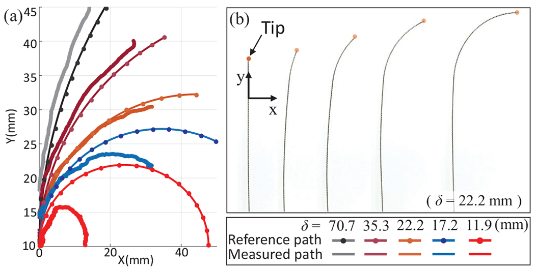
(a) Follow-the-leader motions of the COAST guidewire with respect to given reference paths in free space, (b) Demonstration of the follow-the-leader motion with .
B. Experiment with vascular mock-up model
To validate the proposed COAST guidewire, a vascular phantom model replicating pediatric carotid arteries, aortic arches, and the aortic bifurcation with a range of curvatures between and [23]–[25] was 3D-printed with various paths (see Fig. 9). The guidewire was fed into a linear passage ( in Eq. (11)) and makes a curved shape of constant curvature to follow the given reference path at a bifurcation ( in Eq. (11)). When the distal tip of the robot reaches the end of the curved path, the outer tube slides over the curved middle tube in Eq. (11)) and proceeds further (see Fig. 10), which can provide the stable passage for the middle tube to reach the next operational point as the introducer sheath. The entire procedure is repeated at the next curved path. Therefore, we successfully demonstrated the intervention and navigation function of the proposed COAST guidewire at bifurcations with various curvatures in the vascular phantom model. We believe that this feature can prevent the kinking and breakage issues common with guidewires in current clinical practice without replacement of the guidewire, and provide a stable and fast intervention process to treat CVDs in a minimally invasive manner.
Fig. 9:
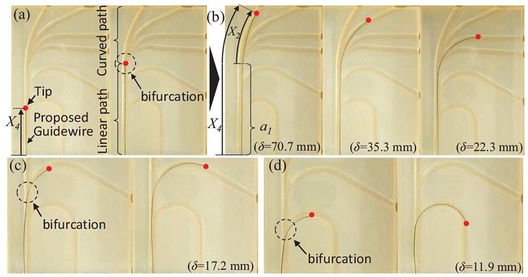
(a) The COAST guidewire is advanced to a point of bifurcations in a linear path, (b)-(d) Given an , the guidewire can advance along any of the channels in the bifurcation. A red dot indicates the guidewire tip.
Fig. 10:

(a)-(d) Advancement of outer tube over the interior tubes after a vessel bifurcation has been successfully crossed .
V. Conclusions and Future Work
In this work, we proposed a novel coaxially aligned steerable (COAST) guidewire robot designed using three coaxial tubes and a single tendon. Independent control of the bending arc length and the curvature allows the robot to follow the vascular curvatures of varying lengths and bending angles using its inherent follow-the-leader motion. Kinematic and static models of the robot were derived and a control algorithm was proposed based on these models to control the COAST mechanism. This prototype of the robot has a diameter of , which is compatible with commercially used guidewires. The performance of the proposed mechanism was evaluated in free space and with a phantom vascular model. We demonstrate that the robot is successfully able to pass through several high curvature vascular structures. In our future work, we will work towards the navigation and control of this proposed guidewire robot through three dimensional phantom vasculature with vascular stiffness properties and a pulsatile blood flow system under fluoroscopic guidance.
Supplementary Material
Acknowledgments
This paper was recommended for publication by Editor Pietro Valdastri upon evaluation of the Associate Editor and Reviewers’ comments. Research reported in this publication was supported in part by the National Heart, Lung, And Blood Institute of the National Institutes of Health under Award Number R01HL144714. The content is solely the responsibility of the authors and does not necessarily represent the official views of the National Institutes of Health.
References
- [1].Benjamin EJ, Virani SS, Callaway CW, Chamberlain AM, Chang AR, Cheng S, Chiuve SE, Cushman M, Delling FN, Deo R et al. “Heart disease and stroke statistics-2018 update: a report from the american heart association.” Circulation, vol. 137, no. 12, p. e67, 2018. [DOI] [PubMed] [Google Scholar]
- [2].Biondi-Zoccai G, Agostoni P, Sangiorgi G, Dalla LP, Armano F, Nicolini S, Alek J, and Fusaro M, “Mastering the antegrade femoral artery access in patients with symptomatic lower limb ischemia: learning curve, complications, and technical tips and tricks.” Catheterization and cardiovascular interventions: official journal of the Society for Cardiac Angiography & Interventions, vol. 68, no. 6, pp. 835–842, 2006. [DOI] [PubMed] [Google Scholar]
- [3].Ellis SG, Vandormael MG, Cowley MJ, DiSciascio G, Deligonul U, Topol EJ, and Bulle TM, “Coronary morphologic and clinical determinants of procedural outcome with angioplasty for multivessel coronary disease. implications for patient selection. multivessel angioplasty prognosis study group.” Circulation, vol. 82, no. 4 , pp. 1193–1202, 1990 [DOI] [PubMed] [Google Scholar]
- [4].Lee JJ, Kim JS, Jeong WS, Kim DY, Hwang SM, and Lim SY, “A complication of subclavian venous catheterization: extravascular kinking, knotting, and entrapment of the guidewire-a case report,” Korean journal of anesthesiology, vol. 58, no. 3, p. 296, 2010. [DOI] [PMC free article] [PubMed] [Google Scholar]
- [5].Merit Medical Systems, “Amplatz left,” https://meritoem.com/product-category/catheters-extrusions/diagnostic-cardiology/performa/amplatzleft/, [Online; accessed 11-February-2020].
- [6].Surmely J-F and Suzuki T, “Parallel-wire techniques,” Chronic Total Occlusions: A Guide to Recanalization, pp. 83–86, 2009. [Google Scholar]
- [7].Atmakuri SR, Lev EI, Alviar C, Ibarra E, Raizner AE, Solomon SL, and Kleiman NS, “Initial experience with a magnetic navigation system for percutaneous coronary intervention in complex coronary artery lesions,” Journal of the American College of Cardiology, vol. 47, no. 3, pp. 515–521, 2006. [DOI] [PubMed] [Google Scholar]
- [8].Wagner LK, McNeese MD, Marx MV, and Siegel EL, “Severe skin reactions from interventional fluoroscopy: case report and review of the literature,” Radiology, vol. 213, no. 3, pp. 773–776, 1999. [DOI] [PubMed] [Google Scholar]
- [9].Kim Y, Parada GA, Liu S, and Zhao X, “Ferromagnetic soft continuum robots,” Science Robotics, vol. 4, no. 33, p. eaax7329, 2019. [DOI] [PubMed] [Google Scholar]
- [10].Kim J, Nguyen PB, Kang B, Choi E, Park J-O, and Kim C-S, “A novel tip-positioning control of a magnetically steerable guidewire in sharply curved blood vessel for percutaneous coronary intervention,” International Journal of Control, Automation and Systems, vol. 17, no. 8, pp. 2069–2082, 2019. [Google Scholar]
- [11].Chitalia Y, Wang X, and Desai JP, “Design, modeling and control of a 2-dof robotic guidewire,” in 2018 IEEE International Conference on Robotics and Automation (ICRA). IEEE, 2018, pp. 32–37. [Google Scholar]
- [12].Soyama T, Yoshida D, Sakuhara Y, Morita R, Abo D, and Kudo K, “The steerable microcatheter: a new device for selective catheterisation,” Cardiovascular and interventional radiology, vol. 40, no. 6, pp. 947–952, 2017. [DOI] [PubMed] [Google Scholar]
- [13].Amanov E, Nguyen T-D, and Burgner-Kahrs J, “Tendon-driven continuum robots with extensible sections—a model-based evaluation of path-following motions,” The International Journal of Robotics Research, p. 0278364919886047, 2019. [Google Scholar]
- [14].Sears P and Dupont P, “A steerable needle technology using curved concentric tubes,” in 2006 IEEE/RSJ international conference on intelligent robots and systems. IEEE, 2006, pp. 2850–2856. [Google Scholar]
- [15].Webster RJ III, Romano JM, and Cowan NJ, “Mechanics of precurved-tube continuum robots,” IEEE Transactions on Robotics, vol. 25, no. 1, pp. 67–78, 2008. [Google Scholar]
- [16].Lee D-Y, Kim J, Kim J-S, Baek C, Noh G, Kim D-N, Kim K, Kang S, and Cho K-J, “Anisotropic patterning to reduce instability of concentric-tube robots,” IEEE Transactions on Robotics, vol. 31, no. 6, pp. 1311–1323, 2015. [Google Scholar]
- [17].Oliver-Butler K, Epps ZH, and Rucker DC, “Concentric agonist-antagonist robots for minimally invasive surgeries,” in Medical Imaging 2017: Image-Guided Procedures, Robotic Interventions, and Modeling, vol. 10135. International Society for Optics and Photonics, 2017, p. 1013511. [Google Scholar]
- [18].Swaney PJ, York P, Gilbert HB, Webster RJ III, Mahoney AW, and Wellborn P, “Surgical device tip with arc length varying curvature,” Mar. 21 2019, uS Patent App. 16/176,068.
- [19].York PA, Swaney PJ, Gilbert HB, and Webster RJ, “A wrist for needle-sized surgical robots,” in Robotics and Automation (ICRA), 2015 IEEE International Conference on. IEEE, 2015, pp. 1776–1781. [DOI] [PMC free article] [PubMed] [Google Scholar]
- [20].Chitalia Y, Wang X, Nguyen V, Melkote S, Chern J, and Desai JP, “Design and analysis of a bidirectional notch joint for a robotic pediatric neuroendoscope,” in International Symposium on Experimental Robotics. Springer, 2018, pp. 24–33. [Google Scholar]
- [21].Jeong S, Chitalia Y, and Desai JP, “Miniature force sensor based on dual-photointerrupter with high linearity and disturbance compensation,” IEEE Sensors Journal, vol. 20, no. 11, pp. 5855–5864, 2020. [Google Scholar]
- [22].Chitalia YC, Jeong S, Deaton N, Chern JJ, and Desai JP, “Design and kinematics analysis of a robotic pediatric neuroendoscope tool body,” IEEE/ASME Transactions on Mechatronics, 2020. [Google Scholar]
- [23].Alberta HB, Secor JL, Smits TC, Farber MA, Jordan WD, and Matsumura JS, “Differences in aortic arch radius of curvature, neck size, and taper in patients with traumatic and aortic disease,” journal of surgical research, vol. 184, no. 1, pp. 613–618, 2013. [DOI] [PubMed] [Google Scholar]
- [24].Jamil M, Tan GXY, Huq M, Kang H, Lee ZR, Tang PH, Hu XH, and Yap CH, “Changes to the geometry and fluid mechanics of the carotid siphon in the pediatric moyamoya disease,” Computer methods in biomechanics and biomedical engineering, vol. 19, no. 16, pp. 1760–1771, 2016. [DOI] [PubMed] [Google Scholar]
- [25].Shah P, Scarton H, and Tsapogas M, “Geometric anatomy of the aortic–common iliac bifurcation.” Journal of anatomy, vol. 126, no. Pt 3, p. 451, 1978. [PMC free article] [PubMed] [Google Scholar]
Associated Data
This section collects any data citations, data availability statements, or supplementary materials included in this article.


