

Abstract
Lithium-ion (Li-ion) battery has played a key role for the development of electric vehicle (EV) at present, while the Li-ion batteries in the market come from different manufactures. Verifying the performance of the battery management system (BMS) for various battery chemistries is a complex undertaking. This paper proposes a high-fidelity Li-ion battery emulator for EV applications. The emulator utilizes a battery model parameterized by a series of performance tests and a special-designed hardware platform. A three-order battery equivalent circuit model (ECM) is selected to provide the voltage and current reference signal in the processor. Subsequently, the hardware generates the high voltage and current signal in accordance with the reference. To ensure the high accuracy of the battery ECM, a 37 Ah nickel manganese cobalt (NMC) battery was selected for testing under both charge and discharge conditions, as well as across a temperature range of − 30℃ to 45℃. The battery emulator is verified on charge and discharge mode for both accuracy and dynamic performance validations.
Keywords: Lithium-ion battery, Emulator, Equivalent circuit model, Electric vehicle
Subject terms: Batteries, Energy science and technology
Introduction
With the widespread popularity of electric vehicles (EVs), Lithium-ion (Li-ion) batteries as their power core have received unprecedented attention1,2. The performance of Li-ion batteries is directly related to the driving range, safety and service life of EVs3–5. Therefore, it is of paramount importance to accurately simulate and test them. In this context, Li-ion battery simulator, as a tool that can effectively simulate the performance of batteries under various working conditions, is widely used in the development and testing of EV battery management systems (BMS)6,7. At present, the research on Li-ion battery simulator has made some progress. These simulators can simulate the basic electrochemical characteristics of batteries, such as voltage, current, temperature, etc., providing an important testing platform for the development of EVs. However, existing simulators still have some limitations in terms of accuracy, dynamic response and adaptability, and it is difficult to fully meet the needs of increasingly complex EV applications. For example, current Li-ion battery simulators are often difficult to take into account both the speed and accuracy of dynamic response when simulating high-precision battery behavior8,9. In addition, with the continuous emergence of new battery materials, the adaptability of simulators to different battery types has become a challenge. Many simulators can only be tested for a specific type of battery, and are not flexible enough to respond to the diverse battery needs in the market. Therefore, the development of a high-performance Li-ion battery simulator is of great significance for the application of BMS and EVs. This paper proposes a high-power simulator for EV and BMS development, which uses third-order RC equivalent circuit model (ECM) and a parameterization method considering a wide temperature range. It is expected that the simulator can effectively improve its accuracy, dynamic response ability, and adaptability to different battery types, thereby better serving the research and testing of EVs.
The main contributions of this paper lie in the following three aspects.
(1) A high-fidelity battery emulator (maximum 600 A) is designed including both the software and hardware system, and its accuracy is validated on both charge and discharge mode and the dynamics response conditions.
(2) The parameters of the three-order RC ECM are calculated in three different polarization time scales according to the electrochemical reactions inside a Li-ion battery.
(3) A three-order RC ECM-based battery emulator is capable of adapting to a variety of state of charge (SOC) and temperatures. Its parameters are extracted from a 37 Ah nickel manganese cobalt (NMC) battery with a wide temperature range (45℃, 25℃, 10℃, 0℃, − 10℃, − 30℃).
The context has five sections. Section II introduces the system design of the battery emulator. Section III shows the parameterization method for the three-order RC ECM under various SOCs and temperatures. Section IV validates the performance of the battery emulator. Section V presents the conclusion of this paper.
Related work
Recently, many studies focus on simulating the characteristics of the Li-ion battery accurately with ECM or electrochemical model10,11. Hu et al. compared 12 lumped Li-ion battery models in literature including the combined model, zero-state hysteresis model, the enhanced self-correcting model and also the first/second/third order ECM models, etc.12. Among all the battery models, ECM has proven to be a better choice for both NMC and LiFePO4-based battery13. In addition, many scholars have studied common electrochemical models, mainly discussing pseudo-two-dimensional (P2D) model, single particle model (SPM) and extended SP model14–16. Although electrochemical models appear to be an accurate solution for battery simulation, the initialization of the model requires the input of a significant number of microscopic parameters, which are not readily available. Furthermore, the partial differential equations of electrochemical models also impose a significant computational burden, rendering real-time simulation impractical. The comparison of various battery model types also proves that ECM model is a good balance of accuracy and complexity, which compares ECM with SPM in dynamic driving cycles17. Krewer et al. also pointed out that even though electrochemical models have good accuracy, they are not suitable for real-time execution due to computational burden18. In recent years, with the development of artificial intelligence, some researchers have attempted to establish data-driven battery models19. Abu-Seif et al. proposed a dynamic mode decomposition linear model to model the Li-ion battery, which subsequently facilitated the estimation of an accurate SOC20. Huang et al. proposed a data-driven model with Gaussian process regression to estimate the battery state of health21. Although those data-driven models show good performances in different applications, large dataset and high performance processor are needed for using the data driven methods. As a result, data-driven model should also not be the first choice of a battery emulator. It is important to note that the aforementioned research is limited to the software level, without any consideration of hardware simulation or the interaction of the simulator with a real BMS. The above studies illustrate that the ECM model strikes a good balance between accuracy and complexity, is suitable for multiple types of Li-ion batteries, and performs well in dynamic driving cycles. However, ECM models may not adequately capture the electrochemical processes inside the battery, especially under extreme conditions (such as high temperature, low temperature, or rapid charge and discharge). In addition, the parameters of the model may vary with changes in battery life and usage environment, and need to be updated regularly to ensure accuracy. Electrochemical models (such as P2D, SPM) provide a deep understanding of the chemical reactions inside the battery with high precision. However, electrochemical models require a substantial number of microscopic parameters within the battery, which may be impractical in practical applications. In addition, electrochemical models are computationally heavy and difficult to achieve real-time simulation, especially in systems that require fast responses. Finally, data-driven battery models can be trained on large data sets to accurately estimate the state of the battery. However, these models are highly dependent on the quality and quantity of data. In situations where the dataset is limited or of low quality, the accuracy of the model can be severely affected. In addition, the data-driven approach requires high-performance processors to do a lot of data computation and storage, which can be a limiting factor in some application scenarios. In conclusion, while numerous battery models have been discussed in the literature, each model possesses distinctive advantages and application scenarios. Currently, no single model is capable of performing optimally across all aspects.
In addition to software simulation, a limited number of works have been created that employ a combination of hardware and software to design a battery simulator22. Barreras et al. designed a hardware in the loop (HIL) simulation system for BMS testing, which uses a host PC and dSPACE GmbH to establish the test bench23. It was not difficult to understand that such a system could not provide the high power of the commercial battery at present. Bui et al. used a similar HIL simulation structure with dSPACE, and a real battery tester MACCOR was also involved in the test bench. The function of the simulator was still limited by the power24. Buccolini et al. added a 48 V power source to increase the voltage ability of the battery simulator25. Messier et al. proposed an OPAL-RT-based simulator that can supply voltage and current to multiple cells26. Nevertheless, the current capacity of the power amplifier is limited to 2 A, which is considerably below the actual current output of the commercial battery27. Hidalgo-León et al. simulated ICR-26650 Li-ion battery with a three-phase interleaved DC-DC boost converter, and the battery was also modeled by two-order RC ECM28. Although the good accuracy of the emulator was proved by experimental validation, the proposed battery emulator could only work in discharge mode and the maximum current was limited to 25 A. For the purpose of conducting a comprehensive validation of its performance and quality, BMS requires the battery simulator to be employed at both the signal level and the high power level29. Although the experimental verification proves the good accuracy of the simulator, the proposed battery simulator has major problems in terms of power and current limitations. In the context of actual production testing, BMS requires not only signal-level battery simulators, but also high-power-level battery simulators to fully verify its performance and quality. The performance of the current simulator is not sufficient to meet the standards required for practical applications.
The preceding studies indicate that while the proposed data-driven model exhibits satisfactory application effects, it demands high performance and is therefore unsuitable for use in battery emulators. In addition, most of the hardware simulators proposed at present can only work in discharge mode, and the maximum current is limited to 25 A, so the application effect in the actual production test is not good. Therefore, to better simulate the battery of EVs, a high-fidelity Li-ion battery simulator is proposed in this study, which is expected to improve the simulation accuracy of EV batteries, so as to promote the development of EVs.
Battery emulator system
For the purpose of high power level simulation, the battery emulator in this paper consists of both hardware and software system. The overall system design principle is illustrated as shown in Fig. 1, which includes a three-order RC ECM battery model with parameters update and a scalable high-power supply to provide enough power for loads in EV. The power supply is provided by the Delta-Q Technologies brand, with a power rating of 600A and an adjustable voltage range up to 4.2 V. LabVIEW software is used to control the hardware system to achieve accurate voltage and current output.
Fig. 1.

The overall system design of the battery emulator.
The battery model is running in a real-time system for providing the references voltage and current to the power supply. The power supply can output as high as 600 A current to meet the requirements of the commercial battery, and H bridge modules are utilized to finish the power conversion. Simulation of the battery performance is one of the key techniques for the overall emulator system. The parameters should be fully used to build the three-order RC ECM. In this paper, the structure of battery model is established as shown in Fig. 2.
Fig. 2.

Battery simulation model in the system.
Figure 2 shows the structure diagram of the battery simulation model used in the battery simulator system, it is necessary to mention that the voltage and current from the load will be measured and then provided as feedback to the battery simulator. In this way, the SOC can be updated in a timely manner, while also establishing a comprehensive control framework for the entire system. According to the temperature setting and the SOC, the parameters of the battery model can be renewed by checking the 3D look-up tables. The establishment of the 3D loop-up tables will be detailed in Section III. Utilizing the structures in Figs. 1 and 2, the emulator can provide high power to the load for BMS verification or other EV tests. In reality, the working environment of EVs is very complex. An accurate battery model needs to consider factors such as temperature, SOC, and aging. To build a high-fidelity Li-ion battery emulator for EV, the ECM is selected as the basic model due to its good trade off of accuracy and complexity. The three-order RC ECM is selected as illustrated in Fig. 3 for a better accuracy, which is a high order choice in literature30–32.
Fig. 3.
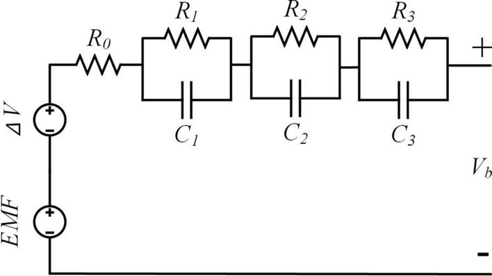
Three-order battery ECM.
As shown in Fig. 3 three-order RC ECM consists of two voltage sources (EMF and ΔV) and three RC network (R1C1, R2C2, and R3C3). EMF is the electromotive force of battery. ΔV means the voltage hysteresis after battery charge or discharge. The three RCs R1C1, R2C2, and R3C3 represent the Ohmic polarization, concentration polarization and electrochemical polarization. According to the above definitions, the equations of the three-order RC ECM can be expressed, as shown in Eq. (1).
| 1 |
Vb(t) is the battery terminal voltage. R0 represents the internal resistance. V1(t), V2(t), and V3(t) are the three polarization voltages of the battery. Considering the voltage response of the RC network as the zero state, the following Eq. (2) can be obtained for calculating the voltages of each RC.
| 2 |
| 3 |
| 4 |
For modeling a battery with three-order RC ECM, Eqs. (1)-(4) have already enough to provide a suitable voltage reference signal. If the parameters such as R1, C1, R2, C2, R3, C3, EMF and ΔV are properly defined, the three-order RC ECM battery model can be used as a battery simulator. However, the parameters of the battery ECM cannot be directly measured due to the sealed case outside of the battery and the fact that the parameters are variable with temperature and SOC, which makes parameter identification challenging in practice33.
Parameter Identification of the ECM with SOC and Temperature Variations
As previously described, the parameters of the three-order RC ECM are varied with external factors such as SOC and temperature. Accurate identification of the parameters for the battery model is extremely a critical task for the battery simulation. A test procedure is designed here that considers both temperature and SOC variation. This is achieved by using a current pulse to obtain the parameters in a three-order RC ECM, as shown in Fig. 4.
Fig. 4.

The test procedure for parameterizing the three-order ECM.
The over test procedure starts from setting a proper test temperature TeoC in a thermostat. When the battery reaches its thermal equilibrium (more than 4 h), capacity test will be initialized to measure the battery capacity at first. During the capacity test, the battery needs to be charged with constant charge constant voltage (CCCV) and discharged using constant current. Afterwards, the current pulse test is executed to measure the values for the RC elements. In current pulse test, the battery firstly charges with Ic to a specific SOC = x and rests for 1.5 h to reach its internal equilibrium. Then, the previous two steps repeat until the battery is fully charged. A similar procedure is used for current pulse test during discharge process. It is important to note that the CCCV mode is employed to charge the battery when the SOC is above 95% to mitigate the risk of overcharge. Similarly, CC is utilized for discharging in current pulse tests. Once the SOC approaches 0% or 100%, the termination of the test will be triggered by evaluating the battery terminal voltage rather than all tested SOC. To finish the test, the values in Table 1 are set for defining the details in the test procedure.
Table 1.
The setting of the test procedure.
| Variable | Value |
|---|---|
| Te | 45 °C, 25 °C, 10 °C, 0 °C, − 10 °C, − 30 °C |
| x | 5%, 10%, 20%, 30%, 40%, 50%, 60%, 70%, 80%, 90%, 95% |
| y | 95%, 90%, 80%, 70%, 60%, 50%, 40%, 30%, 20%, 10%, 5% |
As listed in Table. 1, the Te includes seven different temperature levels ranging from − 30 °C to 45 °C. During the test, the battery SOC changes with 10% interval from 0 to 100%. Two measured points SOC = 5% and 95% are inserted into x and y. A 37 Ah NMC battery, whose parameters are listed in Table 2, is chosen as the sample to implement the battery modeling procedure.
Table 2.
The specification of the NCM battery.
| Specification | Value |
|---|---|
| Nominal capacity | 37 Ah |
| Nominal voltage | 3.75 V |
| Vmax | 4.2 V |
| Vmin | 2.75 V |
Table 2 shows that the settings of Vmax and Vmin are 4.25 V and 2.75 V, respectively. Then, the test bench in Fig. 5 is established to finish the procedure in Fig. 4.
Fig. 5.
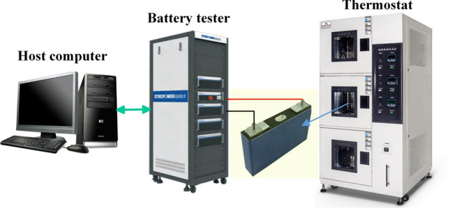
The battery test bench in this work.
As can be seen from Fig. 5, for this battery test, a high-performance battery tester of Stropower brand was selected, which has excellent test accuracy and can provide 0.02% FS (full scale) accuracy, which is ideal for accurate battery performance testing. At the same time, in order to ensure the stability and consistency of the test environment, Tianbo auto thermostat 3,928,639 was selected as the temperature control component. Made of high-quality materials with good thermal conductivity and corrosion resistance, this thermostat is designed for engines such as Shangchai D6114C, Cummins 6CT, Yuchai, etc., but its superior performance is also suitable for battery test environments. Its compact size and precise interface design allow for solid installation, reliable sealing, and stable maintenance of the battery within a preset temperature range to ensure the accuracy and reliability of test data. The sampling time is set to 1 s for all the tests. The test profiles of the battery for capacity test and current pulse test are shown in Fig. 6.
Fig. 6.

The voltage and current of the NMC battery under different conditions. (a) Capacity test, (b) Discharge tests, (c) Charge test.
Figure 6 shows the voltage and current changes of the NMC cell under different conditions, including capacity tests and charge and discharge pulse tests. Figure 6a shows the capacity test profile of the battery which is a combination of CCCV charge and CC discharge. Figures 6b,c are the charging and discharging current pulse test with 1C current rate as the maximum value. Subsequently, the parameters of the three-order RC ECM model can be calculated for the purpose of initializing the battery simulation. In this instance, a voltage response is extracted from the discharging process, as illustrated in Fig. 7.
Fig. 7.
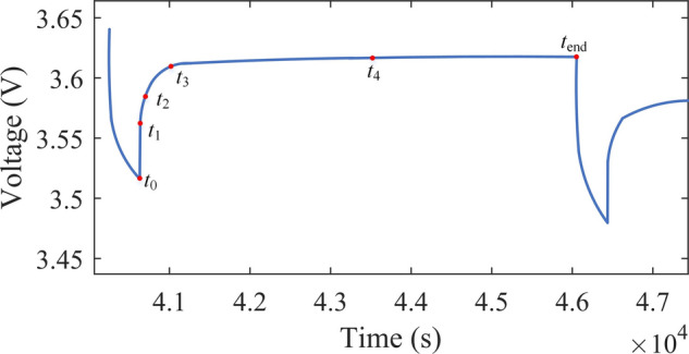
The voltage response during discharge.
Figure 7 shows the voltage response curve extracted during the discharge process, which is used to calculate the parameters of the third-order RC ECM model. The EMF of the battery is obtained from the average OCV of charge and discharge, the calculation formula is expressed as shown in Eq. (5).
| 5 |
OCVcharge and OCVdischage are the battery OCV in charge and discharge test. According to Fig. 7, the voltage at tend can be chose as the OCV. The following Eqs. (6) and (7) are used to obtain the OCVcharge and OCVdischarge.
| 6 |
| 7 |
Next, the voltage hysteresis ΔV between charge and discharge is calculated as shown in Eq. (8).
| 8 |
To calculate those RC elements through the current pulse test, the voltage response can be divided into five sections by t0, t1, t2, t3, t4, and tend. The partitions of the voltage should follow the principle of the time scales for the electrochemical reactions of the battery. The voltage I∙R0 is the instantaneous voltage change after current interruption, mainly caused by the Ohmic resistance of the battery, which is extracted from the voltage response from t0 to t1. The V1(t), V2(t), and V3(t) can be obtained through the time intervals t1-t2, t2-t3, and t3-t4. The following Eqs. (9) and (10) are used to extract the RC parameters from voltage variations. Defining VIR as the voltage variation due to the ohmic resistance, (9) and (10) can be used to calculate R0.
| 9 |
| 10 |
Then, the measurement V1(t), V2(t), and V3(t) are used to calculate the three RC networks using the following Eq. (11).
| 11 |
i can be 1, 2, and 3. As I and t are known in Eq. (11), the rest parameters can be obtained by fitting the voltage curve with the following function.
| 12 |
A and b are the parameter to be determined by the curve fitting methods such as nonlinear least squares.
Once a and b are fitted through the voltage measurement, the RC elements are calculated as shown in Eqs. (13) and (14).
| 13 |
| 14 |
Finally, all the parameters in three-order ECM can be calculated through the above equations. In this work, the parameters of NMC battery are shown in Fig. 8.
Fig. 8.

The calculated parameters of the three-order RC ECM for NMC battery.
Verification of the battery emulator on accuracy and dynamic performance
To verify the accuracy of the designed battery emulator, the same dynamic current profile is given to the emulator in both charging and discharging mode. A comparison of the emulator with the real measurement of the NMC battery is shown in Fig. 9During the comparison and verification process between the battery simulator shown in Fig. 9 and the actual NMC battery in charge and discharge mode, a constant temperature condition was maintained during the pulse test to ensure the accuracy and reliability of the test results. The entire test process is carried out at a standard laboratory temperature of 25 °C ± 2 °C, which is widely used for battery performance testing and helps to reduce the impact of temperature fluctuations on test results.
Fig. 9.

Verification of the battery emulator in charge and discharge mode. (a) Charge test, (b) Discjharge test.
Figure 9 shows the comparison between the battery simulator and the actual NMC battery in charge and discharge mode, which verifies the simulator's high prediction accuracy. In Fig. 9a, under the charging test, the output value of the simulator differs little from the reference value, where the maximum difference and minimum difference are 0.02 V and 0.00 V, respectively. In Fig. 9b, under discharge test, the difference between the output value of the simulator and the reference value is also very small, where the maximum and minimum difference are 0.01 V and 0.00 V, respectively. The above results show that the proposed battery simulator has a high prediction accuracy. In order to further verify the comprehensiveness and accuracy of the battery simulator, it is particularly important to test under different temperature conditions. Table 3 shows the performance of the battery simulator compared to the actual NMC battery at different temperatures.
Table 3.
Detailed performance data comparison between the battery simulator and the actual NMC battery.
| Temperature | Item | Battery simulator | The actual NMC battery | Difference value |
|---|---|---|---|---|
| 25 °C ± 2 °C | Initial voltage (V) | 4.20 | 4.21 | − 0.01 |
| Termination voltage (V) | 3.00 | 3.02 | − 0.02 | |
| Charging Capacity (Ah) | 2.05 | 2.03 | 0.02 | |
| Discharge capacity (Ah) | 1.98 | 2.00 | − 0.02 | |
| Charge and discharge efficiency (%) | 96.3 | 97.5 | − 1.2 | |
| Internal resistance (mΩ) | 85 | 80 | 5 | |
| 0 °C ± 2 °C | Initial voltage (V) | 4.18 | 4.19 | − 0.01 |
| Termination voltage (V) | 2.95 | 2.98 | − 0.03 | |
| Charging Capacity (Ah) | 1.80 | 1.78 | 0.02 | |
| Discharge capacity (Ah) | 1.72 | 1.75 | − 0.03 | |
| Charge and discharge efficiency (%) | 95.5 | 96.5 | − 1.0 | |
| Internal resistance (mΩ) | 120 | 115 | 5 | |
| 45 °C ± 2 °C | Initial voltage (V) | 4.22 | 4.23 | − 0.01 |
| Termination voltage (V) | 2.98 | 3.00 | − 0.02 | |
| Charging Capacity (Ah) | 2.10 | 2.08 | 0.02 | |
| Discharge capacity (Ah) | 2.02 | 2.00 | 0.02 | |
| Charge and discharge efficiency (%) | 96.8 | 97.0 | − 0.2 | |
| Internal resistance (mΩ) | 70 | 65 | 5 |
Table 3 shows the detailed performance data of the battery simulator and the actual NMC battery at 25 °C ± 2 °C, 0 °C ± 2 °C, and 45 °C ± 2 °C respectively. As can be seen from Table 3, under the standard temperature condition of 25 °C ± 2 °C, the initial voltage and termination voltage of the battery simulator are 4.20 V and 3.00 V respectively, which are very close to the measured values of the actual NMC battery (4.21 V and 3.02 V), and the difference is very small. This proves the high accuracy of the simulator in voltage simulation. At the same time, in terms of charging capacity and discharge capacity, the difference between the simulator and the actual battery is 0.02 Ah and -0.02 Ah, respectively, showing the simulator's good performance in capacity simulation. In terms of charge and discharge efficiency, the efficiency of the simulator is 96.3%, while the efficiency of the actual battery is 97.5%, which is acceptable considering that the efficiency of the actual battery is affected by factors such as temperature and aging. As for the internal resistance, the simulator value is 85 mΩ, the actual battery value is 80 mΩ, the difference is 5 mΩ, which is within a reasonable range. At a much lower temperature of 0 °C ± 2 °C, the simulator's initial and termination voltages drop slightly, but the difference from the actual battery is still small. Charging and discharging capacity is also reduced, but the difference between the simulator and the actual battery remains low. The charge and discharge efficiency has decreased, but the difference between the simulator and the actual battery is still small. The internal resistance has increased, but the difference between the simulator and the actual battery remains within a reasonable range. At a higher temperature of 45 °C ± 2 °C, the initial and termination voltages of the simulator rise slightly, while the charging and discharging capacities increase. The charge and discharge efficiency is also improved, and the difference between the simulator and the actual battery is further reduced. The internal resistance decreased, showing the simulator's adaptability to different temperature conditions. In summary, regardless of the temperature conditions, the battery simulator has shown high accuracy and comprehensiveness, and its performance is very close to that of the actual NMC battery. This further verifies the reliability and practicability of the battery simulator. To quantify the accuracy of the battery emulator, mean squared error (MSE) and mean absolute error (MAE) are calculated as listed in Table 4.
Table 4.
The MSE and MAE of the battery emulator.
| Error type | Charge test | Discharge test |
|---|---|---|
| MSE | 5.5433 × 10⁻⁵ | 4.9861 × 10⁻⁵ |
| MAE (V) | 0.1204 | 0.0602 |
It is easily seen from the results that all the parameters change with SOC and temperature. ΔV and EMF vary more significantly with SOC than temperature, while the RC elements are more sensitive to temperature. As the temperature obviously affects the electrochemical reactivity, the resistances increase when temperature becomes lower.
In Table 4, the MSEs are 5.5433 × 10⁻⁵ and 4.9861 × 10⁻⁵, which are both in a very low level. Meanwhile, the MAEs on the two cases are no more than 0.15 V. The good accuracy of the designed battery emulator is proved in this subsection. The dynamic performance of the battery emulator is also quite important for its application, because the response of the battery itself is relatively fast in milliseconds. To validate the results, the voltage of the emulator is first altered from -50 A to -450 A in charge mode, and then a voltage step is defined from 50 to 450 A in discharge mode. The current response of the battery emulator in the above two cases are shown in Fig. 10.
Fig. 10.

The dynamic performance of the battery emulator. (a) –50 A — –450 A. (b) 50 A — 450 A.
Figure 10 shows the dynamic performance of the battery simulator in charge and discharge mode, showing fast response speed and stability. In Fig. 10, when the current steps from -50A to -450A in charging mode, the response time of the simulator is 1 ms, the overshoot is 2.5%, and the stabilization time is 5 ms, showing very fast response speed and stability. In discharge mode, when the current jumps from 50 to 450A, the response time is 2 ms, slightly slower than in charge mode, but the overshoot is smaller, at 1.8%, and the stability time is 6 ms, which also performs well. Overall, the battery simulator has good performance in dynamic response and can meet the rapidly changing current requirements. In summary, through detailed data comparison and analysis, the accuracy and dynamic performance of the designed battery simulator are further verified. The simulator is comparable to the actual NMC battery in terms of voltage, capacity, efficiency, etc. It also demonstrates satisfactory dynamic response, effectively following controller instructions and exhibiting minimal overshoot and rapid stabilization. These results prove the reliability and effectiveness of the battery simulator in practical applications.
Conclusion
This paper proposed a high-fidelity emulator for Li-ion battery in EV application, which can provide current as high as 600 A with low latency less than 2 ms. The overall system structure included a real-time battery simulator as the software to provide the reference for the hardware system. To provide enough accuracy for the simulation, a three-order ECM battery model was designed along with a parametrization method. A 37 Ah NMC battery was subjected to testing in both charge and discharge modes across a range of temperatures, including 45 oC, 25 oC, 10 oC, 0 oC, -10 oC, and -30 oC. This approach enabled the parameters of the three-order ECM to adapt to a variety of SOCs and temperatures, thereby facilitating the development of more robust and effective real-world applications. The reference signals from the battery model such as the voltage and current could be amplified through the hardware, and then the BMS could be validated in power-in-loop conditions. The battery emulator's validations in both charge and discharge conditions demonstrated its high degree of accuracy and the emulator's dynamic response to a 400 A current variation of less than 2 ms with minimal overshoot.
Although the lithium-ion battery simulator proposed in this paper performs well in terms of accuracy, dynamic response and adaptability, there are still some limitations. First, as new battery technologies continue to evolve, simulators need to constantly validate their applicability on different types of batteries. Secondly, the effect of battery aging on the performance of the simulator has not been fully considered, and this factor should be further explored in future studies. In addition, the hardware cost of emulator systems is relatively high, which also limits its popularity in some application scenarios. In view of the above limitations, future work will focus on the following aspects: First, verify the application of battery simulator in a variety of battery technologies to ensure wide applicability; The second is to study the effect of battery aging on the simulator and include it in the model parameterization. Finally, modern computing tools such as neural networks are used to optimize the model to improve the simulation accuracy and adaptability.
Author contributions
Bin Fan: conceptualization, methodology. Baoqing Zhang: writing—original draft preparation, writing—review and editing, formal analysis. Yongxing Shi: investigation. Yanting Chang: software, visualization. All authors have read and agreed to the published version of the man-uscript.
Funding
The work is supported by the National Key R&D Program of China (2022YFB2403900) and the Science and Technology Project of SGCC (State Grid Corporation of China).
Data availability
The original contributions presented in the study are included in the article, further inquiries can be directed to the corresponding author.
Competing interests
The authors declare no competing interests.
Footnotes
Publisher's note
Springer Nature remains neutral with regard to jurisdictional claims in published maps and institutional affiliations.
References
- 1.EV-Volumes: The Electric Vehicle World Sales Database. Available online: https://www.ev-volumes.com/ (accessed on 23 August 2022).
- 2.Liu, W., Placke, T. & Chau, K. T. Overview of batteries and battery management for electric vehicles. Energy Rep.8, 4058–4084. 10.1016/j.egyr.2022.03.016 (2022). 10.1016/j.egyr.2022.03.016 [DOI] [Google Scholar]
- 3.Zhao, G., Wang, X. & Negnevitsky, M. Connecting battery technologies for electric vehicles from battery materials to management. Iscience10.1016/j.isci.2022.103744 (2022). 10.1016/j.isci.2022.103744 [DOI] [PMC free article] [PubMed] [Google Scholar]
- 4.Ouyang, D., Liu, B., Huang, J. & Wang, Z. Degradation and safety performance of lithium-ion cells under high-rate charging/discharging scenarios. Process Safety Environ. Protect.185, 76–85. 10.1016/j.psep.2024.03.064 (2024). 10.1016/j.psep.2024.03.064 [DOI] [Google Scholar]
- 5.Chen, C., Lee, C. & Tang, Y. Fundamental understanding and optimization strategies for dual-ion batteries: A review. Nano-Micro Letters15(1), 121. 10.1007/s40820-023-01086-6 (2023). 10.1007/s40820-023-01086-6 [DOI] [PMC free article] [PubMed] [Google Scholar]
- 6.Han, X. et al. A Review on the key issues of the lithium ion battery degradation among the whole life cycle. eTransportation10.1016/j.etran.2019.100005 (2019). 10.1016/j.etran.2019.100005 [DOI] [Google Scholar]
- 7.Kong, X. et al. Foreign matter defect battery and sudden spontaneous combustion. eTransportation10.1016/j.etran.2022.100170 (2022). 10.1016/j.etran.2022.100170 [DOI] [Google Scholar]
- 8.Feng, X. et al. Thermal runaway mechanism of lithium ion battery for electric vehicles: A review. Energy Storage Mater.10, 246–267. 10.1016/j.ensm.2017.05.013 (2018). 10.1016/j.ensm.2017.05.013 [DOI] [Google Scholar]
- 9.Yuan, X., Zhang, C., Hong, G., Huang, X. & Li, L. Method for evaluating the real-world driving energy consumptions of electric vehicles. Energy141, 1955–1968. 10.1016/j.energy.2017.11.134 (2017). 10.1016/j.energy.2017.11.134 [DOI] [Google Scholar]
- 10.Keil, J. & Jossen, A. Electrochemical modeling of linear and nonlinear aging of lithium-ion cells. J. Electrochem. Soc.10.1149/1945-7111/aba44f (2020). 10.1149/1945-7111/aba44f [DOI] [Google Scholar]
- 11.Plett, G.L. Battery Management Systems, Volume II: Equivalent-Circuit Methods. NewYork: Artech House Publishers, US. (2015).
- 12.Hu, X., Li, S. & Peng, H. A comparative study of equivalent circuit models for li-ion batteries. J. Power Sourc.198, 359–367. 10.1016/j.jpowsour.2011.10.013 (2012). 10.1016/j.jpowsour.2011.10.013 [DOI] [Google Scholar]
- 13.Zhou, J., Xing, B. & Wang, C. A review of lithium ion batteries electrochemical models for electric vehicles. E3S Web Conf10.1051/e3sconf/202018504001 (2020). 10.1051/e3sconf/202018504001 [DOI] [Google Scholar]
- 14.Fuller, T. F., Doyle, M. & Newman, J. Simulation and optimization of the dual lithium ion insertion cell. J. Electrochem. Soc.141, 1–10. 10.1149/1.2054684 (1994). 10.1149/1.2054684 [DOI] [Google Scholar]
- 15.Guo, M., Sikha, G. & White, R. E. Single-Particle model for a lithium-ion cell: Thermal behavior. J. Electrochem. Soc.158, A122. 10.1149/1.3521314 (2011). 10.1149/1.3521314 [DOI] [Google Scholar]
- 16.Khaleghi Rahimian, S., Rayman, S. & White, R. E. Extension of Physics-based single particle model for higher charge: Discharge rates. J. Power Sourc.224, 180–194. 10.1016/j.jpowsour.2012.09.084 (2013). 10.1016/j.jpowsour.2012.09.084 [DOI] [Google Scholar]
- 17.Meng, J. et al. Overview of lithium-ion battery modeling methods for state-of-charge estimation in electrical vehicles. Appl. Sci.8, 659. 10.3390/app8050659 (2018). 10.3390/app8050659 [DOI] [Google Scholar]
- 18.Krewer, U. et al. Review: Dynamic models of li-ion batteries for diagnosis and operation: A review and perspective. J. Electrochem. Soc.165, A3656–A3673. 10.1149/2.1061814jes (2018). 10.1149/2.1061814jes [DOI] [Google Scholar]
- 19.Li, S., He, H., Su, C. & Zhao, P. Data driven battery modeling and management method with aging phenomenon considered. Appl. Energy10.1016/j.apenergy.2020.115340 (2020).33199939 10.1016/j.apenergy.2020.115340 [DOI] [Google Scholar]
- 20.Abu-Seif, M. A., Abdel-Khalik, A. S., Hamad, M. S., Hamdan, E. & Elmalhy, N. A. Data-Driven modeling for li-ion battery using dynamic mode decomposition. Alex Eng. J.61, 11277–11290. 10.1016/j.aej.2022.04.037 (2022). 10.1016/j.aej.2022.04.037 [DOI] [Google Scholar]
- 21.Huang, H. et al. An enhanced data-driven model for lithium-ion battery state-of-health estimation with optimized features and prior knowledge. Automot. Innov.5, 134–145. 10.1007/s42154-022-00175-3 (2022). 10.1007/s42154-022-00175-3 [DOI] [Google Scholar]
- 22.Di Rienzo, R., Verani, A., Baronti, F., Roncella, R. & Saletti, R. Modular battery emulator for development and functional testing of battery management systems: The cell emulator. Electron11, 1215. 10.3390/electronics11081215 (2022). 10.3390/electronics11081215 [DOI] [Google Scholar]
- 23.Barreras, J. V. et al. An advanced HIL simulation battery model for battery management system testing. IEEE Trans. Ind. Appl.52, 5086–5099. 10.1109/TIA.2016.2585539 (2016). 10.1109/TIA.2016.2585539 [DOI] [Google Scholar]
- 24.Bui, T.M.N., Niri, M.F., Worwood, D., Dinh, T.Q., Marco, J. An advanced hardware-in-the-loop battery simulation platform for the experimental testing of battery management system. In Proceedings of the 2019 23rd International Conference on Mechatronics Technology (ICMT), 10.1109/ICMECT.2019.8932115, (2019).
- 25.Buccolini, L., Orcioni, S., Longhi, S., Conti, M. Cell battery emulator for hardware-in-the-loop BMS test. In Proceedings of the 2018 IEEE International Conference on Environment and Electrical Engineering and 2018 IEEE Industrial and Commercial Power Systems Europe (EEEIC / I&CPS Europe), 10.1109/EEEIC.2018.8493731. (2018).
- 26.Messier, P., LeBel, F.-A., Rouleau, J., Trovao, J.P.F. Multi-Cell emulation for battery management system validation. In Proceedings of the 2018 IEEE Vehicle Power and Propulsion Conference (VPPC) 10.1109/VPPC.2018.8604959. (2018).
- 27.Haupt, H., Plöger, M. & Bracker, J. Hardware-in-the-Loop test of battery management systems. IFAC Proc.46, 658–664. 10.3182/20130904-4-JP-2042.00042 (2013). 10.3182/20130904-4-JP-2042.00042 [DOI] [Google Scholar]
- 28.Hidalgo-León, R., Urquizo, J., Litardo, J., Muñoz-Jadán, Y., Singh, P., Wu, J. Simulation of battery discharge emulator using power electronics device with cascaded PI control. In Proceedings of the 2020 IEEE International Conference on Industrial Technology (ICIT), 10.1109/ICIT45562.2020.9067170. (2020)
- 29.Bischof, S., Kuecuek, C., Blank, T., Weber, M. A battery cell emulator for hardware in the loop tests of reconfigurable lithium-ion and post-lithium batteries. In Proceedings of the PCIM Europe 2018; International Exhibition and Conference for Power Electronics, Intelligent Motion, Renewable Energy and Energy Management, 1–7. (2018).
- 30.Zhou, W., Zheng, Y., Pan, Z. & Lu, Q. Review on the battery model and SOC estimation method. Process9, 1685. 10.3390/pr9091685 (2021). 10.3390/pr9091685 [DOI] [Google Scholar]
- 31.Singirikonda, S. & Obulesu, Y. P. Battery modelling and state of charge estimation methods for energy management in electric vehicle: A review. IOP Conf. Ser. Mater. Sci. Eng.937, 12046. 10.1088/1757-899x/937/1/012046 (2020). 10.1088/1757-899x/937/1/012046 [DOI] [Google Scholar]
- 32.Xiong, R., He, H., Guo, H. & Ding, Y. Modeling for lithium-ion battery used in electric vehicles. Procedia Eng.15, 2869–2874. 10.1016/j.proeng.2011.08.540 (2011). 10.1016/j.proeng.2011.08.540 [DOI] [Google Scholar]
- 33.Stroe, A. I. et al. Influence of battery parametric uncertainties on the state-of-charge estimation of lithium titanate oxide-based batteries. Energies11, 735. 10.3390/en11040795 (2018). 10.3390/en11040795 [DOI] [Google Scholar]
Associated Data
This section collects any data citations, data availability statements, or supplementary materials included in this article.
Data Availability Statement
The original contributions presented in the study are included in the article, further inquiries can be directed to the corresponding author.