Abstract
Introduction:
Currents in the brain flow inside neurons and across their boundaries into the extracellular medium, create electric and magnetic fields. These fields, which contain suitable information on brain activity, can be measured by electroencephalography (EEG), magnetoencephalography (MEG), and direct neural imaging.
Methods:
In this paper, we employed an electromagnetic model of the neuron activity and human head to derive electric and magnetic fields (brain waves) using a full-wave approach (ie. without any approximation). Currently, the brain waves are only derived using the quasi-static approximation (QSA) of Maxwell’s equations in electromagnetic theory.
Results:
As a result, source localization in brain imaging will produce some errors. So far, the error rate of the QSA on the output results of electric and magnetic fields has not been investigated. This issue has become more noticeable due to the increased sensitivity of modern electroencephalography (EEG) and magnetoencephalography (MEG) devices. This work introduces issues that QSA encounters in this problem and reveals the necessity of a full-wave solution. Then, a full-wave solution of the problem in closed-form format is presented for the first time. This solution is done in two scenarios: the source (active neurons) is in the center of a sphere, and when the source is out of the center but deeply inside the sphere. The first scenario is simpler, but the second one is much more complicated and is solved using a partial-wave series expression.
Conclusion:
One of the significant achievements of this model is improving the interpretation of EEG and MEG measurements, resulting in more accurate source localization.
Keywords: Brain waves, Quasi-static approximation, Full-wave analysis, Brain imaging, Human head modeling
Highlights
Currently, the brain waves are only derived using the quasi-static approximation of Maxwell’s equations in electromagnetic theory. As a result, source localization in brain imaging can produce some errors
This study provides an electromagnetic model of the neuron activity and human head to derive electromagnetic fields using a full-wave approach (without any approximation).
One of the significant results of the proposed model is improvement in the interpretation of electroencephalography (EEG) and magnetoencephalography (MEG) measurements, resulting in more accurate source localization.
Plain Language Summary
One of the important issues in recognizing brain disorders and cognitive functions is detecting the location and distribution of active neurons in the brain based on the measured electromagnetic fields. To deal with this inverse problem, it is necessary to provide a mathematical model that links neuronal sources to measured signals. Due to the low-frequency nature of brain activity, all of these models have been derived only by quasi-static approximation of Maxwell equations. This study provides an electromagnetic model of the neuron activity and human head to derive electromagnetic fields using a full-wave approach (without any approximation). This method can lead to significant improvement in the interpretation of EEG and MEG measurements, resulting in more accurate source localization.
1. Introduction
Currents in the brain flow inside neurons and across their boundaries into the extra-cellular medium, create electric and magnetic fields. These fields, which contain suitable information on brain activity, can be measured by electroencephalography (EEG), magnetoencephalography (MEG), and direct neural imaging. One of the important issues in recognizing brain disorders and cognitive functions is detecting the location and distribution of active neurons in the brain based on the measured electric and magnetic fields. This process is known as the inverse problem. To handle an inverse problem, it is necessary to provide a mathematical model that links neuronal sources to measured signals. This measurement is a forward problem that calculates the electric and magnetic field produced by a predefined neuronal current in a special location (Supek, 2016; Ito, 2015).
Over the past few decades, several mathematical-electromagnetic models have been used in analytical studies to explain the forward problem (Geselowitz, 1970; Cuffin & Cohen, 1977; Sarvas, 1987). A crucial part of all these models is a volume conductor model that characterizes the effect of head conductivity and permittivity profile on neutrally driven electric currents. The analytic solutions are given for different conductivity profiles, including a single homogenous sphere (Heller, 2004), multilayer non-isotropic sphere (Petrov, 2012; Nieminen & Stenroos, 2016), and even for slightly more realistic spheroidal (Huerta & Gonzalez, 1983; De Munck, 1988; De Munck et al., 1988) and ellipsoidal (Giapalaki & Kariotou, 2006) geometries.
Due to the low-frequency nature of brain activity, all of these models have been derived only by quasi-static approximation (QSA) of Maxwell equations (Malmivuo, 2012). QSA simplifies Maxwell’s equations by ignoring capacitive, inductive, and wave propagation effects (Bossetti et al., 2007). While the extracellular potential is thought to be exclusively generated by the transmembrane currents, recent studies suggest that the extracellular diffusive, advective, and displacement currents may contribute considerably to extracellular potential recordings (Gratiy et al., 2017; Bédard & Destexhe, 2009; Jain & Wiart, 2015). However, QSA implicitly assumes that the tissue conductivity is independent of the physiological range frequency and that the diffusion, advection, and displacement currents are negligible compared to the conductive return current (Gratiy et al., 2017).
To overcome QSA’s issues, we derived a full-wave analytical expression for a current dipole’s electric and magnetic fields positioned into a homogenous conductor sphere. The full-wave analysis results in the enrichment of information obtained from EEG/MEG measurements. To start the full-wave solution, we assume the source is a small current dipole placed into the scatterer (sphere).
Due to the angular dependence of the field components in the boundary, this issue is explored by utilizing the partial-wave series expression (PWSE) technique. The technique solves scattering problems by decomposing constituent angular components of fields to apply boundary conditions (Balanis, 2012; Mitri, 2015).
This paper is organized as follows. Section 2 presents the background knowledge about the generation of EM fields by the neurons. Then, the traditional role of QSA in the solution of EM fields and related references is introduced. Next, some landmark notes and objections about applying QSA in EEG/MEG forward problems are discussed. In section 3, the theoretical equations for the full-wave EEG/MEG forward problem are developed. This part is done in two scenarios: The centered and off-centered sources. For this purpose, the scattering problem for a current dipole inside a sphere is solved using the PWSE technique. Section 4 represents the numerical computations and simulation results to illustrate the theory. Section 5 deals with the convergence of the addition theorem as one of the main challenges of this work. Finally, in the section 6, the conclusions are presented.
2. Problem Overview
Proposed scheme
This section introduces the electromagnetic model of an active neuron inside the brain. When a neuron is activated, a primary current (JP) flows into it. Because the neurons are located in an electrically conducting medium, the extracellular current, the return current (JR), follows a path that depends upon the conductivity profile of the extracellular medium. The return current is the ohmic current that is taken to be the product of the local conductivity σ and the electric field E (JR=σE). So, the total current is J=JP+σE. The primary and return currents form the electric and magnetic fields. Figure 1 shows an active neuron with primary and return currents with induced electric and magnetic fields around it.
Figure 1.
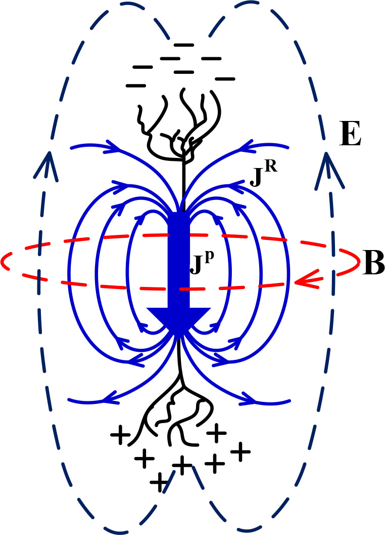
A conceptual representation of an active neuron with volume current distribution and electric and magnetic fields
Since the length of a neuron is negligible compared with the head size, it is assumed that all the primary current is concentrated at a single position r′ and has a moment of p. Thus, the primary current is described by equivalent current dipole and mathematically is written as JP(r)=pδ3(r−r′) where δ is the Dirac delta function. Among different ways to model neurons as the current source, the equivalent current dipole is widely used in clinical applications (Koubeissi & Azar, 2017).
In the forward problem, the electric and magnetic fields are determined from the neuronal current distribution. This calculation is done by the classical electromagnetic theory that is described in Maxwell’s equations as follows:
| 1. |
, where E, B, J, and/are the electric field, magnetic field, current source density, and displacement current density, respectively. Because of the low frequency of neuronal activities, the formulations are traditionally done based on the QSA, ie, ignoring time-varying terms (ie, and ) in the Maxwell’s equations in all corresponding articles and books. The argument is that because the two inequalities 2πfɛ/σ«1 and μ0 σ2πfR2«1 are hold, we can use QSA. In those two inequalities, f is the frequency of neuronal activity, μ0,ɛ and σ are the constitutive parameters of the brain tissue, and R is the radius of the human head (Zakharova et al., 2017; Hämäläinen et al., 1993).
Based on QSA, the analytic solution of a forward problem for special geometries of the head model has been introduced (Geselowitz, 1967; Zhang, 1995). One of the most important shapes is a sphere in which the electrical conductivity is assumed to depend only on the distance from the origin (Doschoris & Kariotou, 2017). This shape approximates the shape of the human head and can serve as a basis for understanding the measurements of the brain’s electric and magnetic fields (Cuffin & Cohen, 1977). Basically, the starting point to derive these field equations is attempting to solve the problem for a simple homogeneous sphere (Cuffin & Cohen, 1977). Derivation of analytical solutions for simplified geometries (such as a sphere) has important roles in EEG/MEG test interpretation, leading to valuable rules-of-thumb, calibration of EEG/MEG equipment, verifying numerical methods for realistic model geometries, and so on.
QSA challenges
As mentioned earlier, due to the low-frequency nature of neuron activities, the time-varying terms in Maxwell’s equations are ignored, resulting in QSA being used. However, QSA has some objections and significant challenges, which are listed below.
First, in physical problems, when a datum is the sum of two or more components so that one of them is much smaller than the other, from an engineering point of view, the smallest component is usually ignored (such as ignoring high-order sentences in Taylor’s expansion). In the literature from 1967 (Plonsey & Heppner, 1967) till now, it is argued that the time-variant terms in Maxwell’s equations(ie, and terms in Equation 1) is negligible, and the form of Maxwell’s equations is reduced to the quasi-static form. Although it simplifies solving the problem, valuable information may be lost. However, this ignorance should be quantitatively investigated to evaluate the electric and magnetic fields. No report uses the perfect form of Maxwell’s equations (full-wave form) to measure the quasi-static errors. Recent advances in neuronal current imaging using more sensitive EEG/MEG devices and better shielding techniques have made measuring the smallest changes in electric and magnetic fields possible. Recently, there have been an EEG with an accuracy level of 2.7 nv/√Hz (Scheer et al, 2011; Fedele et al., 2015) and an MEG with an accuracy level of 0.01fT √cm3/Hz (Dang et al., 2010; Baranga, 2010). So, if the difference between the quasi-static and full-wave results is too low, it is detectable with today’s modern devices.
Second, it has already been mentioned that one of the conditions that establish a quasi-static approximation is (Hämäläinen et al., 1993). Unlike the outside, this condition is correct for inside the head. Because in the outside of the head, σ=0 and then 2πfɛ/σ→∞. Thus, for the outside of the head, time-varying terms are considerable.
Third, Gratiy et al. emphasized that the displacement current (∂D/∂t) in Ampere–Maxwell’s law is responsible for the capacitive charging of neural membranes and cannot be neglected (Gratiy et al., 2017). Furthermore, Albanese and Monk. (2006) stated that “since the goal of the inverse source problem was the monitor of dynamic neuronal events (an action potential has a rise time on the order of 0.5 ms (Wilson, 1999), it might be that the displacement current is not negligible. This problem has already been pointed out in studies of source problems related to monitoring neurons in the arm (Kuiken et al., 2001)”.
Fourth, in all argumentations presented to ignore time-varying terms in Maxwell equations, it is assumed that the brain media is linear, isotropic, and homogeneous. While the human brain does not really have these properties (Vorwerk et al., 2014).
These uncertainties encourage us, for the first time, to solve the forward problem using the full-wave method instead of QSA. Obviously, the full-wave solution of an electromagnetic problem gives the full solution (including time-varying terms), not an approximation. Thus, the above issues have been automatically resolved. In the next section, we establish the full-wave analysis formulation of the problem for two scenarios: One for a centered source and another for an off-centered source.
3. The Full Wave Solution of the Forward Problem
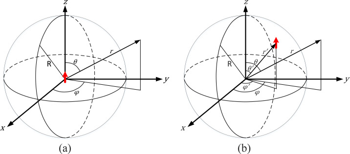
In this section, we want to introduce the convenient relationships for solving the scattering of waves emanating from a finite source placed in a spherical object (scatterer). Let us consider a homogenous conductor sphere of radius R and the electromagnetic parameters of ɛr and σ. Assume that the medium outside the sphere is free space (wave number β0) and inside is a lossy dielectric (wave number β̇d) represented by a relatively complex permittivity ɛ̇d (ɛ̇d=ɛ0 ɛr−j σ/ω). The formulation path can be different depending on the source location inside the sphere (either centered or out of center). For this reason, we represent our formulations in two scenarios: One for a centered source and another for an off-centered source. These scenarios are shown in the Figure 2.
Figure 2.
The current dipole in the structure under study
a) The Current dipole in the center, b) The current dipole in the arbitrary off-centered location
Source origin
We start the problem’s solution in the simplest situation, ie, a source in the center of the desired sphere. Figure 2a shows the geometry of the problem. As can be seen, a current dipole, ie, a very thin linear electric current element of very short length (l<<λ) and a constant current I, as a neuron source, is positioned at the center of the sphere. The problem is finding the EM field inside and outside the conductor sphere. To this end, we use the magnetic vector potential A defined in electromagnetic terminology. The dipole’s incident field can be represented by A (Harrington, 2001):
| 2. |
, where β · d=ω√(μɛ̇r) is the wave number Ĥ1(2) is Schelkunoff spherical Hankel function of the second kind, P1 is the Legendre function of the first kind, and Il is the current dipole moment. The index i in Ari is referred to the incident field from the source to the bounded media. Upon the interaction of the electromagnetic wave with the sphere in its boundary, the scattered beam is composed of two parts: Inside scattered wave (Ars−) and outside scattered wave (Ars+). Because the field must be finite everywhere in the sphere, including r=0, and has a standing form, the inside scattered wave is written as follows:
| 3. |
In the outside of the sphere, the field must have a traveling form as follows
| 4. |
In these equations, b and c are the sphere scattering coefficients to be determined by applying appropriate boundary conditions. The total vector potential is Art−)=Ari+Ars− inside the sphere and Art+=Ars+ outside it. Thus, the electric and magnetic fields are obtained from the following equations by eliminating the zero components (Harrington, 2001).
| 5. |
In which, Ψ equals Art− for r≤R and Ψequals Art+ for r>R. The tangential components of the fields inside and outside the sphere are derived as follows:
| 6. |
| 7. |
| 8. |
| 9. |
By applying the boundary conditions on r=R:
| 10. |
The coefficients and are determined as:
| 11. |
, where
| 12. |
| 13. |
| 14. |
| 15. |
| 16. |
| 17. |
| 18. |
| 19. |
3.2. Source Off-Origin
Now we assume that the source is positioned out of the center in point r′=(r′, θ′, φ′) and oriented along the z-axis. Figure 2b shows the structure. Note that the assumption of the removable z-directed dipole in the problem does not detract from the generality of the problem because the sphere is perfectly symmetrical. The magnetic vector potential is as follows (Harrington, 2001):
| 20. |
, where h0(2) is a spherical Hankel function of the second kind. When dealing with spherical wave scattering of waves generated by current dipole radiator located away from the origin at r′, it is convenient to express its radiation in terms of spherical wave function arising from the origin of the coordinate system. It can be accomplished using the “addition theorem” of spherical wave functions, which states that Equation 20 can be expressed as follows (Harrington, 2001):
| 21. |
, where
Also, Pnm (.) is the associated Legendre function. The reason for choosing a z-directed representation of A instead of radially directed shows that the addition theorem for its radially directed representation is not found. Bessel functions jn (βr) were selected to represent the fields for r<r′ because the field must be finite everywhere, including r=0, and Hankel functions were chosen for r>r′ to represent the traveling nature of the wave. The expression for the inside scattered wave (As−) will be of similar forms as the first expression of Equation 21 and for the outside scattered wave (As+) will be of similar forms as the second expression of Equation 21 and written as follows:
| 22. |
| 23. |
, where and are the sphere scattering coefficients to be determined by applying appropriate boundary conditions. The superscript minus (−) is used to identify the vector potentials and associated fields on and within the sphere (r ≤R), while the plus (+) is used to identify those on and outside the sphere (r≥R).
The appropriate boundary conditions must be applied on the surface of the sphere and the continuity of the tangential electric and magnetic fields. It must derive the total electric and magnetic field inside and outside the sphere. Thus, the total vector potential inside the sphere (At−) is composed of the incident plus inside scattered vector potentials (Ai+As−) and outside the sphere (At+) is only outside scattered vector potential (As+). All the components of the total EM fields, as well as incident plus scattered, can be found from vector potential using the following equations:
| 24. |
| 25. |
| 26. |
| 27. |
In these equations, if we want electromagnetic fields inside the sphere, let Ψ=Azt− and for outside the sphere, let Ψ=Azt+. The scattering coefficients bn and cn for the sphere can now be determined after applying the boundary condition to the total tangent electric field. After simplifying and arrangement, this procedure leads to two systems of linear equations, one for Eθ and the other for Eφ:
| 28. |
| 29) |
, where the functions Γnm (θ, φ), Λnm (θ, φ), and Πnm (θ, φ) in Equation 28 are expressed, respectively, as follows:
| 30. |
and Ψ_nm (θ, φ), Φnm (θ, φ) and Θnm (θ, φ) in Equation 29 are expressed, respectively, as follows:
| 31. |
In equations 30 and 31, the coefficients Anm,Bnm,CnmDnm,Fnm, and Gnm depend only on the structure of the problem (eg, source position, source moment, frequency, sphere radius, sphere material) as follows:
| 32. |
| 33) |
| 34. |
| 35. |
| 36. |
| 37. |
, where the primes denote a derivative with respect to the argument. Note that the functions Γm (θ, φ), Λm(θ, φ), Πm (θ, φ), Ψm (θ, φ), Φm (θ, φ), and Θm (θ, φ) are dependent on the polar angle θ and the azimuthal angle φ for a fixed frequency or wave number β. The angular dependency must be eliminated to solve the system of linear Equations 28 and 29. To this end, first, it is required to expand the boundary condition of Equations 28 and 29. in PWSEs with separable variables and match each partial wave n, m. Accordingly, Equations 28 and 29. are equated to the Laplace series as follows:
| 38. |
| 39. |
, where Ynm (θ, φ) is spherical harmonic function. To remove the dependence on the polar angle and the azimuthal angle, the following orthogonality conditions can be applied to equations 38 and 39:
| 40) |
, whereYpq* (θ, φ) denotes the complex conjugate of the spherical harmonic function Ypq (θ, φ) and δ_ij is the Kronecker delta function. Equating the left- and right-hand sides in equations 38 and 39 for each partial wave and applying the orthogonality condition of Equation 40, a new system of linear equations is obtained, which allows appropriate determination of the scattering coefficients bn and cn for the sphere. They are now rewritten as follows:
| 41. |
, where
| 42. |
| 43. |
| 44. |
| 45. |
| 46. |
| 47. |
The procedure for determining bn and cn requires first the determination of Equation 42 through Equation 47 by numerical integration. Once the scattering coefficients bn and cn are obtained, they can be used to compute the field components by inserting Equation 21 through Equation 23 into Equation 24 through Equation 27.
4. Numerical Results and Discussion
We simulated the magnetic field for a point current dipole with a moment 700 nA.m in a homogeneous sphere of radius 8 cm. Also, the conductivity of the sphere is chosen at 0.33 S/m, representative of the brain’s white and gray matter based on the available anatomical data (Petrov, 2012; Nieminen & Stenroos, 2016).
Centered source
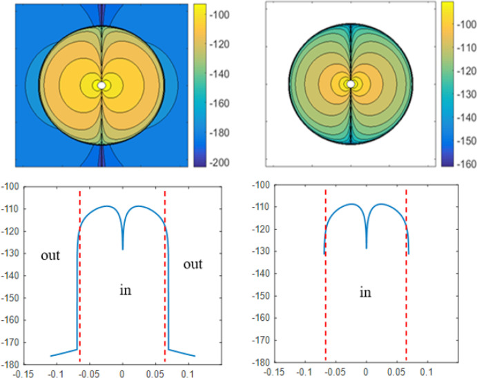
For a centered current source scenario, the coefficients b and c in equations 3 and 4 are calculated from Equation 11. The magnetic field distribution in the yz-plane due to a current dipole positioned at the center of the sphere is shown in Figure 3 using a MATLAB® code. In this Figure, the values are translated to dB for better coloring.
Figure 3.
The magnetic field pattern of a current dipole at the sphere center
Up-right) 2D simulation by using QSA, Up-left) 2D simulation by using the full-wave analysis, Down-right) Sampled values of quasi-static magnetic field on horizontal line passed through the sphere center, Down-Left) Sampled values of full-wave magnetic field on horizontal line passed through sphere center
The magnetic field distribution and pattern in both analyses match, showing that full-wave analysis can play a reliable role in future research. As an important note that can be seen from Figure 3, in quasi-static analysis, the outside magnetic field is zero because, in a quasi-static regime, a radial dipole creates no magnetic field outside the conductor (Sarvas, 1987). In applying MEG, the full-wave analysis shows attainable data out of the head, which contrasts with the QSA method. In other words, in full-wave analysis, the field is not zero, and MEG should not be eliminated from the radial sources. It is worth noticing that in the present traditional MEG analysis, the radial-oriented neurons are not detected at all, while the full-wave analysis can detect these neurons.
For a better comparison of these two solutions, we used the relative difference measure (RDM) (Meijs et al., 1989).
| 48. |
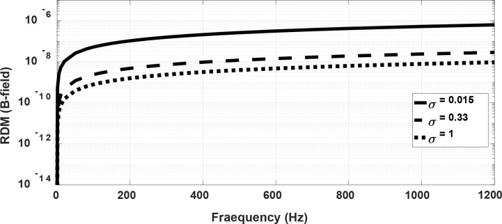
In Equation 48, i is the number of each node, BiQ is the magnetic field obtained from QSA and BiF is the magnetic field obtained from full-wave analysis. We divided the square of the result in Figure 3 into N=700×700 nodes and sampled the magnetic field in each node. The full-wave magnetic field is saved in different frequencies, from 1 to 1200 Hz, and RDM is calculated for each frequency. Figure 4 shows the RDM of the magnetic field as a function of frequency in three conductivity values. As seen in this Figure, the difference between QSA and full-wave results has been increased by raising the frequency, and the necessity of a full-wave solution is more sensed. We especially see a difference between these two in the MEG frequency range (0.1–1000 Hz). Furthermore, the higher the conductivity, the greater the difference would be, indicating that the more conductive layers of the human head lead to the greater the error in QSA.
Figure 4.
Relative difference measure between quasi-static and full-wave magnetic field as a function of frequency for three values of conductivity
Off-centered source
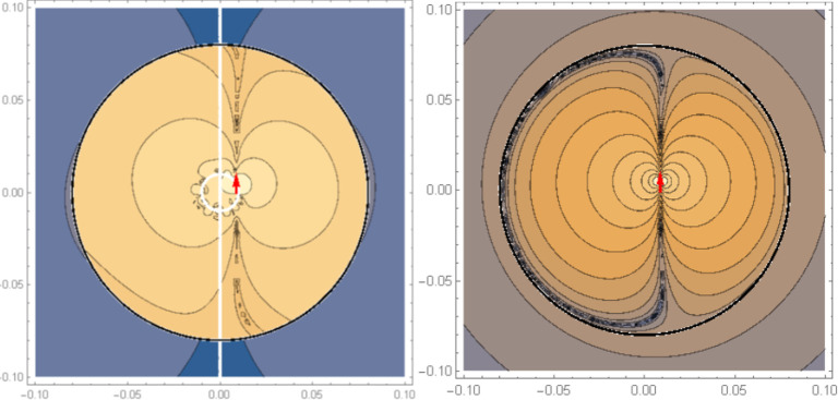
In the scenario of an off-centered dipole, the coefficients and are calculated by developing a Mathematica code to obtain the numerical solution of the system of linear Equation 41 through Equation 47. Distributions of magnetic fields over the sphere’s cross section at yz-plane produced by a z-directed dipole source (positioned at r′=2 cm, θ′=60°, φ′=90°) are shown in Figure 5. The right picture is the magnetic field derived from QSA based on Equation 7, and the left one is from full-wave analysis at 1000 Hz based on the equations included in section 3, part B. Both simulations have the same pattern and behavior inside and outside the sphere.
Figure 5.
The magnetic field pattern of a current dipole in a homogenous sphere with conductivity of 0.33 S/m
Right) Quasi-static, Left) Full-wave
To better compare the two methods above, the sampled values of fields on a horizontal line passed from the center of the sphere, ie, on the line z=0 in the yz-plane, are shown in Figure 6. The right curve is the magnetic field derived from quasi-static approximation, and the left one is from full-wave analysis. The comparison of the two curves shows that the results obtained by PWSE full-wave are excellent. In the other off-centered points, we have a challenge described in the next section.
Figure 6.
The magnetic field in yz-plane sampled at line z=0
Left) Full-wave, Right) Quasi-static
These results provide an advanced approach to accurately compute the brain’s electromagnetic fields for a relatively simple structure. This outcome shows that for more complex structures (e.g. multilayer sphere, etc.) and near-surface sources, the error rate of QSA results is significant. The accurate resolution of full-wave analysis can help people interpret the EEG and MEG data more precisely and nearer to real in the inverse problem for source localization. Of course, it should be noted that the full-wave analysis requires more calculations than QSA, which is one of the drawbacks of this approach. However, this approach will be under more development in the future, and its benefits will become more evident, especially with powerful processing and modern measurement equipment.
5. Convergence of Addition Theorem
The addition theorem helps solve electromagnetic and acoustic scattering problems. It is a series expansion of off-center Bessel and Hankel functions to separate field points and source points from each other. In other words, the addition theorem transforms the implicit form of Bessel and Hankel functions into the explicit form referred to as the origin. The addition theorem of the spherical Hankel function of zero-order and the second kind is given in the Equation 49:
| 49. |
, whereand. cos ξ = cos θ cos θ′+ sin θ sin θ′ cos(φ − φ′) and .
In these equations, ξ is the angle between r and r′ and r=(r, θ, φ) and (r′)=(r′, θ′, φ′) are the locations of the field point and source point, respectively. In other words, this equation attributes an out-of-center source to the summation of weighted-centered sources. This outcome enables engineers to solve many problems related to acoustic and electromagnetic scattering. However, the addition theorem encounters a critical problem in the vicinity of r′, ie, the lack of convergence in this region. To demonstrate this, we evaluate the addition theorem in r=r′. Thus, it should be a concern to both sides of Equation 49 to consider r equal to r′ as derived in below:
| 50. |
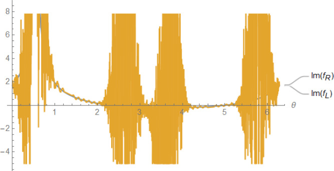
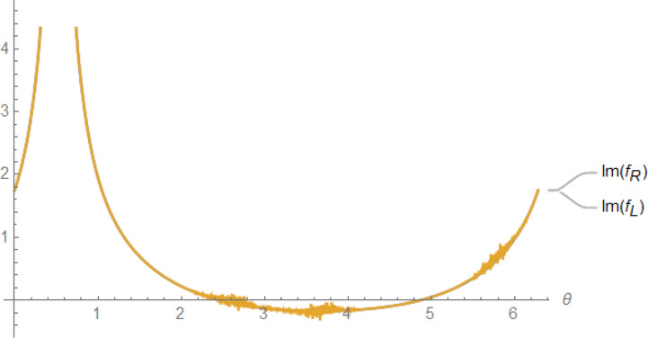
On both sides of Equation 50, θ and φ (not r′) are variables. For convenience, we named the right-hand side of this Equation as fR (θ, φ) and the left-hand side as fL (θ, φ). Then, we draw the curve of each side of this Equation, ie, the curve of fR (θ, φ) and fL (θ, φ), in terms of θ and at a fix φ. In the right-hand side of Equation 50, the number of terms (N) in summation is an important parameter. Increasing this parameter reveals the convergence/divergence behavior of summation. The curve of real and imaginary parts of fR (θ, φ) and fL (θ, φ)) is plotted in Figure 7 for N=20.
Figure 7.
Real and Imaginary Parts of fR (θ, φ) and fL (θ, φ)
As seen in Figure 7, the real part of the two expressions is exactly equal; thus, the series expansion of the off-center spherical Hankel function is convergent. But the imaginary part of the series expansion of off-center spherical Hankel function fR (θ, φ) has oscillations around its analytic formula. A question arises: What are the results when N is large? To answer this question, we plotted the curves for a larger value of N=50. Figure 8 shows the result. The imaginary part of the series expansion is divergent and unstable at large N. The curve of the imaginary part of both sides of Equation 50 at r=0.9r′ for N=50 is plotted in Figure 9. This Figure reveals the farther we go from the r′, the better the convergence situation. It indicates the improvement of series converges as moving away from r′. This challenge stops the extraction of other point results to compare QSA and full-wave PWSE, the subject of our future works.
Figure 8.
Imaginary part of fR (θ, φ) at N=50
Figure 9.
Imaginary part of series expansion at r=0.9r′ with N=50
6. Conclusion
This paper has opened a new window to investigate brain waves using the full-wave method instead of the traditional QSA method. We have argued the need for full-wave analysis to derivate the brain’s electric and magnetic fields. We derived a full-wave solution to analytically predict the electric and magnetic field from a current source (current dipole) inside a spherical conductor. It was done using a formal solution based on the auxiliary vector potential and scattering theory. The problem was once solved for a centered source and then an off-centered source. Thus, we used the PSWE technique in the off-centered source to apply appropriate boundary conditions and eliminate angular dependence. The results showed the merits of full-wave solution over quasi-static solution and encouraged us to continue in a professional format. The difference between these two in the MEG frequency range (0.1–100 Hz) shows the importance of the full wave for brain wave analysis. Our detailed simulations will be presented in the next article, and our goal here was to represent the idea of full-wave analysis of brain waves.
Ethical Considerations
Compliance with ethical guidelines
There is no ethical consideration to be considered in this research.
Funding
This paper was taken from the PhD dissertation of Sattar Samadi, approved by Department of Electrical Engineering, Faculty of Electrical and Computer Engineering, Babol Noshirvani University of Technology.
Authors’ contributions
All authors equally contributed to preparing this article.
Conflict of interest
The authors declared no conflict of interest.
References
- Albanese R., Monk P. B. (2006). The inverse source problem for Maxwell’s equations. Inverse Problems, 22(3), 1023. [DOI: 10.1088/0266-5611/22/3/018] [DOI] [Google Scholar]
- Balanis C. A. (2012). Advanced engineering electromagnetics. New Jersey: John Wiley & Sons. [https://www.google.com/books/edition/Advanced_Engineering_Electromagnetics/_q35KChOfVwC?hl=en&gbpv=0] [Google Scholar]
- Baranga A. B. (2010). Brain’s magnetic field: A narrow window to brain’s activity. Electromagnetic field and the human body workshop, 1–30 [https://scholar.google.com/scholar?q=Baranga%2C%2BA.%2BB.%2B(2010).%2BBrain%E2%80%99s%2Bmagnetic%2Bfield%3A%2Ba%2Bnarrow%2Bwindow%2Bto%2Bbrain%E2%80%99s%2Bactivity.&hl=en&as_sdt=0%2C5]
- Bédard C., Destexhe A. (2009). Macroscopic models of local field potentials and the apparent 1/f noise in brain activity. Biophysical Journal, 96(7), 2589–2603. [DOI: 10.1016/j.bpj.2008.12.3951] [DOI] [PMC free article] [PubMed] [Google Scholar]
- Bossetti C. A., Birdno M. J., Grill W. M. (2007). Analysis of the quasi-static approximation for calculating potentials generated by neural stimulation. Journal of Neural Engineering, 5(1), 44–53. [DOI: 10.1088/1741-2560/5/1/005] [DOI] [PubMed] [Google Scholar]
- Cuffin B. N., Cohen D. (1977). Magnetic fields of a dipole in special volume conductor shapes. IEEE Transactions on Bio-Medical Engineering, 24(4), 372–381. [DOI: 10.1109/TBME.1977.326145] [DOI] [PubMed] [Google Scholar]
- Dang H. B., Maloof A. C., Romalis M. V. (2010). Ultrahigh sensitivity magnetic field and magnetization measurements with an atomic magnetometer. Applied Physics Letters, 97(15), 151110. [DOI: 10.1063/1.3491215] [DOI] [Google Scholar]
- De Munck J. C. (1988). The potential distribution in a layered anisotropic spheroidal volume conductor. Journal of Applied Physics, 64(2), 464–470. [DOI: 10.1063/1.341983] [DOI] [Google Scholar]
- De Munck J. C., Van Dijk B. W., Spekreijse H. (1988). Mathematical dipoles are adequate to describe realistic generators of human brain activity. IEEE Transactions on Biomedical Engineering, 35(11), 960–966. [DOI: 10.1109/10.8677] [DOI] [PubMed] [Google Scholar]
- Doschoris M., Kariotou F. (2017). Mathematical foundation of electroencephalography. Electroencephalography. London: In-Tech. [DOI: 10.5772/68021] [DOI] [Google Scholar]
- Fedele T., Scheer H. J., Burghoff M., Curio G., Körber R. (2015). Ultra-low-noise EEG/MEG systems enable bimodal non-invasive detection of spike-like human somatosensory evoked responses at 1 kHz. Physiological Measurement, 36(2), 357–368. [DOI: 10.1088/0967-3334/36/2/357] [DOI] [PubMed] [Google Scholar]
- Geselowitz D. (1970). On the magnetic field generated outside an inhomogeneous volume conductor by internal current sources. IEEE Transactions on Magnetics, 6(2), 346–347. [DOI: 10.1109/TMAG.1970.1066765] [DOI] [Google Scholar]
- Geselowitz D. B. (1967). On bioelectric potentials in an inhomogeneous volume conductor. Biophysical Journal, 7(1), 1–11. [DOI: 10.1016/S0006-3495(67)86571-8] [DOI] [PMC free article] [PubMed] [Google Scholar]
- Giapalaki S. N., Kariotou F. (2006). The complete ellipsoidal shell-model in EEG imaging. Abstract and Applied Analysis, 2006, 1–18. [DOI: 10.1155/AAA/2006/57429] [DOI] [Google Scholar]
- Gratiy S. L., Halnes G., Denman D., Hawrylycz M. J., Koch C., Einevoll G. T., et al. (2017). From Maxwell’s equations to the theory of current-source density analysis. The European Journal of Neuroscience, 45(8), 1013–1023. [DOI: 10.1111/ejn.13534] [DOI] [PMC free article] [PubMed] [Google Scholar]
- Hämäläinen M., Hari R., Ilmoniemi R. J., Knuutila J., Lounasmaa O. V. (1993). Magnetoencephalography-theory, instrumentation, and applications to noninvasive studies of the working human brain. Reviews of Modern Physics, 65(2), 413. [DOI: 10.1103/RevModPhys.65.413] [DOI] [Google Scholar]
- Harrington R. F. (2001). Time-harmonic electromagnetic fields. New York: McGraw-Hill. [DOI: 10.1109/9780470546710] [DOI] [Google Scholar]
- Heller L., Ranken D., Best E. (2004). The magnetic field inside special conducting geometries due to internal current. IEEE Transactions on Biomedical Engineering, 51(8), 1310–1318. [DOI: 10.1109/TBME.2004.827554] [DOI] [PubMed] [Google Scholar]
- Huerta M. A., Gonzalez G. (1983). The surface potentials produced by electric sources in stratified spherical and prolate spheroidal volume conductors. International Journal of Electronics, 54(5), 657–671. [DOI: 10.1080/00207218308938765] [DOI] [Google Scholar]
- Ito T., Otsubo H., Shiraishi H., Yagyu K., Takahashi Y., Ueda Y., et al. (2015). Advantageous information provided by magnetoencephalography for patients with neocortical epilepsy. Brain and Development, 37(2), 237–242. [DOI: 10.1016/j.braindev.2014.04.006] [DOI] [PubMed] [Google Scholar]
- Jain S. M., Wiart J. (2015). Full wave modeling of brain waves as electromagnetic waves. Progress In Electromagnetics Research, 151, 95–107. [DOI: 10.2528/PIER15011404] [DOI] [Google Scholar]
- Koubeissi M. Z., Azar N. J. (2017). Epilepsy board review a comprehensive guide. Berlin: Springer. [DOI: 10.1007/978-1-4939-6774-2] [DOI] [Google Scholar]
- Kuiken T. A., Stoykov N. S., Popović M., Lowery M., Taflove A. (2001). Finite element modeling of electromagnetic signal propagation in a phantom arm. IEEE Transactions on Neural Systems and Rehabilitation Engineering: A Publication of the IEEE Engineering in Medicine and Biology Society, 9(4), 346–354. [DOI: 10.1109/7333.1000114] [DOI] [PubMed] [Google Scholar]
- Malmivuo J. (2012). Comparison of the properties of EEG and MEG in detecting the electric activity of the brain. Brain Topography, 25(1), 1–19. [DOI: 10.1007/s10548-011-0202-1] [DOI] [PubMed] [Google Scholar]
- Meijs J. W., Weier O. W., Peters M. J., van Oosterom A. (1989). On the numerical accuracy of the boundary element method (EEG application). IEEE Transactions on Biomedical Engineering, 36(10), 1038–1049. [DOI: 10.1109/10.40805] [DOI] [PubMed] [Google Scholar]
- Mitri F. G. (2015). Axisymmetric scattering of an acoustical Bessel beam by a rigid fixed spheroid. IEEE Transactions on Ultrasonics, Ferroelectrics, and Frequency Control, 62(10), 1809–1818. [DOI: 10.1109/TUFFC.2014.006811] [DOI] [PubMed] [Google Scholar]
- Nieminen J. O., Stenroos M. (2016). The magnetic field inside a layered anisotropic spherical conductor due to internal sources. Journal of Applied Physics, 119(2), 1–12. [DOI: 10.1063/1.4939469] [DOI] [Google Scholar]
- Petrov Y. (2012). Anisotropic spherical head model and its application to imaging electric activity of the brain. Physical Review. E, Statistical, Nonlinear, and Soft Matter Physics, 86(1 Pt 1), 011917. [DOI: 10.1103/PhysRevE.86.011917] [DOI] [PubMed] [Google Scholar]
- Plonsey R., Heppner D. B. (1967). Considerations of quasi-station-arity in electrophysiological systems. The Bulletin of Mathematical Biophysics, 29(4), 657–664. [DOI: 10.1007/BF02476917] [DOI] [PubMed] [Google Scholar]
- Sarvas J. (1987). Basic mathematical and electromagnetic concepts of the biomagnetic inverse problem. Physics in Medicine and Biology, 32(1), 11–22. [DOI: 10.1088/0031-9155/32/1/004] [DOI] [PubMed] [Google Scholar]
- Scheer H. J., Fedele T., Curio G., Burghoff M. (2011). Extension of non-invasive EEG into the kHz range for evoked thalamocortical activity by means of very low noise amplifiers. Physiological Measurement, 32(12), N73–N79. [DOI: 10.1088/0967-3334/32/12/N02] [DOI] [PubMed] [Google Scholar]
- Supek S., Aine C.J. (2016). Magnetoencephalography, from signals to dynamic cortical networks. Berlin: Springer Berlin Heidelberg. [https://www.google.com/books/edition/_/XJsVvgAACAAJ?hl=en&sa=X&ved=2ahUKEwjx3pmWgIiHAxWQwAIHHZNkDrMQ7_IDegQICRAE] [Google Scholar]
- Vorwerk J., Cho J. H., Rampp S., Hamer H., Knösche T. R., Wolters C. H. (2014). A guideline for head volume conductor modeling in EEG and MEG. NeuroImage, 100, 590–607. [DOI: 10.1016/j.neuroimage.2014.06.040] [DOI] [PubMed] [Google Scholar]
- Wilson H. R. (1999). Spikes, decisions, and actions: The dynamical foundations of neurosciences. Oxford: Oxford University Press. [https://books.google.de/books?id=6LzZngEACAAJ&hl=de&source=gbs_book_other_versions] [Google Scholar]
- Zakharova T. V., Karpov P. I., Bugaevskii V. M. (2017). Localization of the activity source in the inverse problem of magnetoencephalography. Computational Mathematics and Modeling, 28(2), 148–157. [DOI: 10.1007/s10598-017-9353-6] [DOI] [Google Scholar]
- Zhang Z. (1995). A fast method to compute surface potentials generated by dipoles within multilayer anisotropic spheres. Physics in Medicine & Biology, 40(3), 335–349. [DOI: 10.1088/0031-9155/40/3/001] [DOI] [PubMed] [Google Scholar]


