

Abstract
A dislocation-density based crystalline plasticity (DCP) and nonlinear finite element (FE) analysis were used to predict, and fundamentally understand how and why fracture nucleation and propagation are related to the interrelated microstructural mechanisms of dislocation-density pileups, GB structure, orientation, and total and partial dislocation density interactions within and adjacent for a random low angle grain boundary (LAGB) and a random high angle GB (HAGB). The GB orientations and structures were obtained from micropillar experiments, such that LAGBs and the HAGBs can be accurately represented and used for the modeling predictions. The normal stress, density of pileups, and dislocation-density accumulation along and within the GB were higher for the low angle GB bicrystal. These interrelated phenomena delineate how fracture for high angle GBs nucleate and propagate at lower nominal strains than the lower angle GB bicrystal case. These predictions underscore how fundamental mechanisms can be identified and used to understand how failure nucleates and propagates for different GB structures and orientations.
Subject terms: Mechanical properties, Metals and alloys
Introduction
Intergranular (IG) fracture is one of the dominant failure modes in crystalline metals and alloys. Hence, it is essential to fundamentally understand the reliability and durability of aerospace, nuclear, marine, and myriad materials, and systems. One of the significant microstructural defects that affect failure at different scales are grain-boundary (GB) orientations and structures and how they interact with planar defects, such as dislocations. Local dislocation density interactions along and within GBs not only strengthen1, but can also affect the nucleation of transgranular and intergranular fracture modes2–4.
SEM in situ tensile experiments for Cu bicrystal specimens indicate that high-angle GBs can impede slip bands and lead to necking and fracture5. TEM bicrystal tensile tests for gold show that Shockley partial dislocations can enclose stacking faults (SFs) that form at the GB in each grain before fracture occurs6. Moreover, Shockley partial dislocations and SFs are precursor events for crack nucleation, as atomistic investigations for various GBs in crystalline materials have shown. For example, MD simulations have delineated how Shockley partials in f.c.c. CSL GBs are adjacent to crack nucleation sites7, and SFs are ahead of IG crack fronts for symmetric tilt GBs of h.c.p. magnesium8. In addition, experiments related to nickel-based super alloys, such as Inconel 718, indicate how perfect and partial dislocation interactions, with precipitates and GBs, can result in dislocation pileups, which leads to IG creep fracture9,10. Partial dislocations can be emitted by GBs, which can form twins7,8. However, experiments and observations based on high resolution TEM and SEM and atomistic scale models are limited due to temporal and spatial scales and the inability to gain a fundamental understanding of evolving microstructural behavior, such as large strain deformation and failure modes11.
On the microstructural scale, experimental observations have shown that the morphology and structure of GBs is linked to phenomena, such as dislocation-density pileups, which can be a dominant event leading to fracture nucleation. Random high angle GBs (HAGB) can have pileups12,13, as well as low angle GBs (LAGB)14,15. Furthermore, mesoscale approaches have shown how pileups leading to stress accumulation or fracture nucleation, such as crystal plasticity16–18, discrete dislocation dynamics18,19, and phase field modeling20,21. These investigations further underscore that a fundamental understanding is needed to quantify how GB structures and orientations affect defect interactions, such as dislocation-densities, and how this is related to fracture nucleation and propagation.
Hence, this investigation will focus on total and partial dislocation-density interactions and pileups, for a representative low angle and high angle GB, and how this is linked to IG fracture nucleation and propagation. We couple a dislocation density based crystalline plasticity (DCP) framework with a proposed fracture criterion specifically tailored to dislocation-density pileups and the transmission or blockage of dislocation-densities adjacent to and within the GBs. This paper is organized as follows: the DCP for total and partial dislocations and the proposed fracture approach are detailed in Section II; the experimental approach is discussed in Section III; the Results and Discussion are given in Section IV for the low angle and high angle GBs; and a summary is given in Section V.
Dislocation density coupled crystalline plasticity (DCP) formulation and intergranular fracture (IG) approach
DCP formulation
To account for defect evolution in DCP, the dislocation density evolution equations incorporate mobile, and immobile, dislocation density22. The mobile and immobile dislocation densities are statistically stored quantities that are independent from grain size and specimen size. As the deformation evolves, the two types of dislocation density are coupled with the strain rate in the evolution Eqs. (3) of the -th slip system as
| 1 |
where the different coefficients correspond to different mobile and immobile dislocation interactions and mechanisms as outlined in Table 1. The coefficients, which are assumed as unknown are updated at each increment, are discussed in detail in the previous work22.
Table 1.
Coefficients for the evolution equations.
| Expression | General coefficient description | |
|---|---|---|
| Dislocation-density source term | ||
| Mobile and immobile dislocation density interactions | ||
| Recovery for annihilation of dislocation-densities |
The DCP formulation and numerical approach2,21–23 are based on first assuming a reference shear stress, , of the -th slip system that is based on the Taylor formulation as
| 2 |
where is the static yielding stress; is the shear modulus; nss is the total number of the slip system; is the Burger's vector on the slip system; is the reference temperature; is the thermal softening exponent; is the immobile dislocation density; and is the Taylor coefficient that account for dislocation interaction. This representation is for statistically stored densities22–24 and does not explicitly account for grain-size effects. Grain-size effects are accounted in the FE domain, and the grain sizes are based on the experimental EBSD measurements.
To determine the partial dislocation-densities, the Taylor coefficients are obtained based on dislocation interactions that perfect dislocation density are decomposed into Shockley partial dislocation densities. A minimum energy criterion is used to identify resultant partials for each perfect dislocation-density interaction16,22,25–27. The perfect dislocation-densities relevant to each interaction can be obtained by a distribution tensor, as
| 3 |
where and correspond to the different slip-systems16. The distribution tensor allocates the dislocation density of slip system α to each slip interaction based on the density of slip system β. A binary mapping tensor, is then obtained for each partial dislocation-density interaction, and is then used to determine partial dislocation-density, , as
| 4 |
where the partials are given in Table 2. The shear strain rate is defined as
| 5 |
where the shear strain rate is a function of the resolved stress with as the rate sensitivity parameter; is the reference shear slip rate; and the grain boundary transmission factor () is defined with the GB energy barriers , and normalized by the Boltzmann constant, k, and Kelvin temperature, T, that are discussed in Refs.2,28,29 and is given by
| 6 |
where and are geometric constant, , is effective Burger’s vector and is defined by the residual Burger’s vector and the intersection angles, , of incoming and outgoing slip planes28,29.
Table 2.
Partial dislocation-densities .
| Shockley | Shockley | Lomer | ||||||
| Lomer | 1/3 [001] | Hirth | ||||||
| 1/3 [100] | ||||||||
| 1/3 [010] |
Intergranular fracture criteria
The dislocation density blockage at GBs can lead to dislocation density pileups. To determine dislocation density pileup, Orowan’s relation are utilized to include the traveling speed with the slip-rate. The dislocation density pileup rate was defined as
| 7 |
where GB width, w, and effective residual Burger’s vectors, , were normalized with Burger’s vector16. The effective residual Burger’s vectors are the difference between the slip directions in the two neighboring grains forming the GB. By integrating though solution increments, the dislocation density of pileups is obtained by integrating with time step as
| 8 |
where the initial pileup density, , is chosen as the initial immobile dislocation density.
The number of pileups is defined as the pileup density times the local area of the GB areas. Since plane strain is used, the local GB area is defined as GB width times the unity in the out of plane direction as
| 9 |
where the width of the GB, , is chosen as 1.5 times of the lattice constant, and is a geometric constant defined with the square root of the ratio of the GB length and the lattice constant as 258 for the demonstration model in these sections16. The critical fracture stress associated with intergranular (IG) criterion is defined as2
| 10 |
where h is the interplanar spacing which is chosen as of Burger’s vector magnitude. This critical fracture stress is used as a criterion by comparing it with the tractions on the GB planes to further determine the failure modes, so if the critical stress (10) is exceeded, then crack nucleation is initiated based on
| 11 |
where stands for the normalized normal directions of GB planes. This fracture approach is implemented with the phantom node overlap method developed by Zikry and as detailed in Ref.2.
Experimental approach
To validate the GB orientations, structures, and loading orientations two micropillar compression experiments were undertaken for a low angle and a high angle GB. The details of these micropillar experiments are given in Ref.16, and only a brief outline will be given here. An oxygen-free high-thermal-conductivity (OFHC) copper plate was utilized here, which underwent heat treatment at 900 under a vacuum of 5.4 × 10⁻⁵ mbar for a duration of 35 min. Micropillars, consisting of two crystal grains, were fabricated with dimensions of 7.5 μm in diameter and 15 μm in height, utilizing the focused ion beam (FIB) technique employing the cutting-edge FEI Helios 600 Nanolab DualBeam system. For the final polishing stage, a beam current of 100 pA and a voltage of 30 keV were applied. To enable real-time visualization of the fabrication process, a Hysitron/Bruker PI-89 Picoindentor equipped with a diamond indenter tip with 10 μm in diameter was employed. This led to a quasi-static strain rate of approximately 10−3 s−1 in the Thermo Fisher Scientific Apreo SEM. Subsequently, post-experiment analysis involved slip trace examination using MATLAB in combination with the MTEX package15, enhancing the accuracy and efficiency of the analysis process.
Results and discussions
A micropillar, comprising two grains separated by a LAGB, was prepared for investigation shown in SEM images (Fig. 1a). The image obtained after compression reveals consistent and uniform traces across the boundary at 15% nominal strain. The micropillar underwent homogeneous deformation, leading to a smooth side surface. The schematic diagrams of slip traces of both grains are given in Fig. 1b, which show the dominant slip systems were identified as for Grain 1 and for Grain 2. Shown in Fig. 1c, the inverse pole figure (IPF) map of the top surface presents the EBSD measurements that the misorientation angle associated with the GB is approximately 7 degrees. The loading direction of Grain 1 is near [] (1.0000 -3.1170 1.8027), while Grain 2 was loaded along [1 2 1] (1.0000 1.9917 0.7962).
Fig. 1.

The results of LAGB bicrystal pillar. (a) The front and back view secondary electron image of the pillar after compression showing the slip traces in Grain 1 and Grain 2. (b) Schematic diagram of slip traces in Grain 1 and Grain 2. (c) Inverse pole figures (IPF) map showing the orientation of the top surface of the pillar.
For the HAGB case, the details of the micropillar can be found in our previous work16. For the HAGB case, the GB is precisely positioned at the midpoint of the pillar, and it is aligned perpendicular to the compression direction. The slip traces apparent on the side surface conspicuously on the grain boundary plane. This phenomenon likely results from incompatible slip in the two adjoined grains. The slip on these systems shears the two grains individually in different directions, and it leads to a clear offset or cracking along the boundary plane. In Grain 1, the dominant slip systems are , , and . Conversely, the primary slip systems in Grain 2 are and . Based on the Inverse Pole Figure (IPF) map of the upper surface for the HAGB, the measured misorientation angle associated with the boundary is approximately 39°.
From the experimental measurements and observations, the HAGB pillar has the more conspicuous slip traces and discontinuities at the HAGB. The discontinuity of dislocation density pileups and normal stress accumulation are consistent with the modeling results detailed in Ref.16, but more importantly shows how slip on different slip systems behaves near GBs, and it is almost continuous and uniform across the LAGB. The more distinct slip traces and offset would imply IG cracks were more likely to occur in HAGBs. For the modeling predictions, a tensile displacement load is applied perpendicular to the GBs, while, in experiments, the compressive direction is parallel to the GBs. Even with these inherent differences in boundary and loading conditions, there are similarities in the bulge directions. More importantly the GB orientations from the micropillar experiments were used for the LAGBs and the HAGBs in the modeling for a physical representation of GB orientation and structures.
For modeling the IG fracture modes, two GB misorientations, a low-angle and a high-angle GB misorientation, are shown in Fig. 2a and were obtained by varying the orientations of the bottom grain. The bicrystal model consists of a reference grain (Grain 1) with a cube texture and a misoriented grain (Grain 2). The maximum low angle misorientations was five, and the maximum high angle misorientation was 30° from the normal direction (ND). The stereographic projections of the two bicrystals are shown in Fig. 2b, the circles correspond to the reference grain, the triangles correspond to the random low-angle model GB, and the diamonds correspond to the high-angle GB model.
Fig. 2.
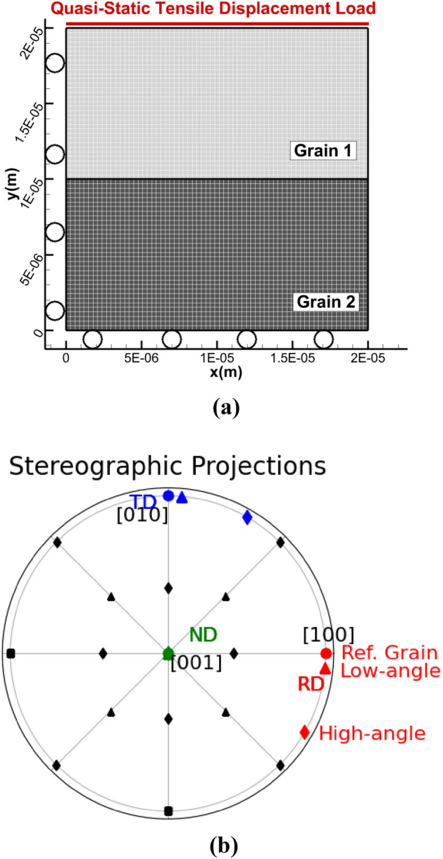
Grains of (a) the bicrystal with quasi-static loading conditions, (b) stereographic projections of the random high-angle GB (diamonds) and the low-angle random GB (triangles) models with Grain 1 as the reference grain (circles).
Both bicrystals were subjected to a quasi-static tensile displacement load along the top edge, while constrained with roller boundaries on the left and bottom edges for geometrical symmetry. The displacement load is aligned with the normal direction (ND), for a tensile strain rate of 10−4 s−1 for plane strain loading conditions. A nonlinear FEM method as detailed in Refs.2,23 with a convergent mesh of 4422 elements was used. The material properties are given in Table 3.
Table 3.
Modeling parameters.
| Parameter | Values |
|---|---|
| Young’s modulus, | 110 GPa |
| Poisson ratio | 0.3 |
| Static yielding stress, | 110 MPa |
| Cleavage plane fracture stress, | 440 MPa |
| Initial mobile density, | 106 m−2 |
| Initial immobile density, | 108 m−2 |
| Saturation density, | 1015 m−2 |
| Loading strain rate, | 10−4 s−1 |
The normalized global stress-stain behavior for both cases are shown in Fig. 3, where red corresponds to the random low angle GB, and green corresponds to the random high angle GB. The LAGB attained a maximum normalized load of 2.6 times (the stresses were normalized by the static yield stress) before fracture nucleation, which corresponds to a global unloading at 0.8% nominal strain. The random HAGB attained a normalized load of 2.3 before fracture nucleation at 0.4% nominal strain. As seen in Fig. 3, the high angle GB unloads or fractures at an earlier nominal strain than the low angle GB.
Fig. 3.
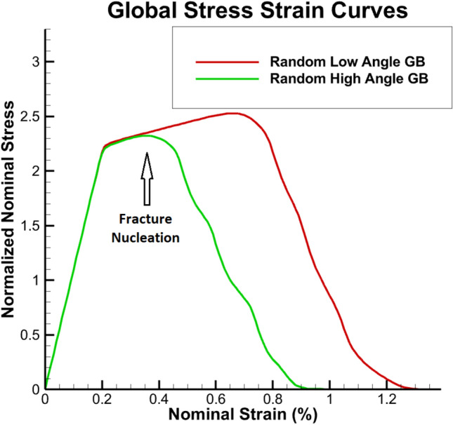
Normalized global stress–strain responses (the stresses were normalized by static yield, 110 MPa) of the low-angle and the high angle GB fractures earlier than the low-angle GB model.
To gain further understanding of these global events, the normalized normal local stress contours at 0.8% nominal strain for both the random low- and high-angle GBs were obtained. The normal stress for the low angle GB case (Fig. 4a) had a normalized normal stress accumulation ahead the crack front of approximately 3.8 times. For the high angle GB case (Fig. 4b), the normal stress accumulation ahead of crack front, had a normalized normal stress of 3.6. Based on this, the stresses for the LAGB are slightly higher than the HAGB by approximately 5.5%. At this nominal strain, for the LAGB case, the crack has just started to nucleate an IG crack, as denoted by the red box in Fig. 4a, whereas, the IG crack had already elongated 13 µm for the HAGB (Fig. 4b).
Fig. 4.
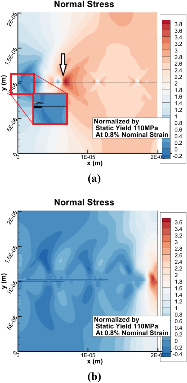
The normal stress distribution in (a) the low-angle model with the maximum normalized value of 3.8 times of the static yield, and in (b) the high angle model with a maximum normalized stress of 3.6.
It is evident that IG fracture is more likely for the HAGB than the LAGB. To further understand why, the shear slip (total accumulated plastic strain on all active slip systems) is shown in Fig. 5a for the low angle GB and in Fig. 5b for the high angle GB at the same nominal strain of 0.8%. There is slightly higher shear slip for the high angle case, but the maximum values are behind the crack front, which indicates that there is not enough shear slip activity ahead of the crack front, which would impede or blunt the long crack pertaining to the high angle case. These localized shear slip patterns occur due to the dislocation-density activities near the GB. And as they evolved, they propagated to the free boundary in different bands. This is consistent with experimental observations related to localized shear slip5,6. Furthermore, cracks can nucleate at low nominal strains in f.c.c. materials. Experimentally, it is difficult, if not impossible, to show nucleation, in-situ. But an MD investigation by Ref.30, has shown that voids in aluminum bicrystals can nucleate under tension, at nominal strains much lower than 1%. They attribute this to the large GB width of bicrystals and the interactions of dislocations with the GB.
Fig. 5.

Shear slip at 0.8% nominal strain of (a) the low-angle GB case and (b) the high angle GB case, where the fracture nucleation sites are denoted with white arrows.
Furthermore, this has also been substantiated by experiments for copper and steel at different strain-rates that indicate crack nucleation can occur at relatively low strains31.
This can be further substantiated by the GB dislocation-density activities near the crack nucleation and propagation sites. The normalized total dislocation density pileups, based on Eqs. (6) and (7) (which were normalized by the initial mobile dislocation density) for the low angle GB case (Fig. 6a) and the high angle GB case (Fig. 6b), dislocation-density pile-ups play a significant role. For the most active slip system, , at 0.8% nominal strain, the maximum normalized GB pileups density is 85, while for the high angle GB, it is 38. This indicates that the high angle GB case required lower dislocation-density pileups before nucleating IG fracture than the low angle GB case.
Fig. 6.
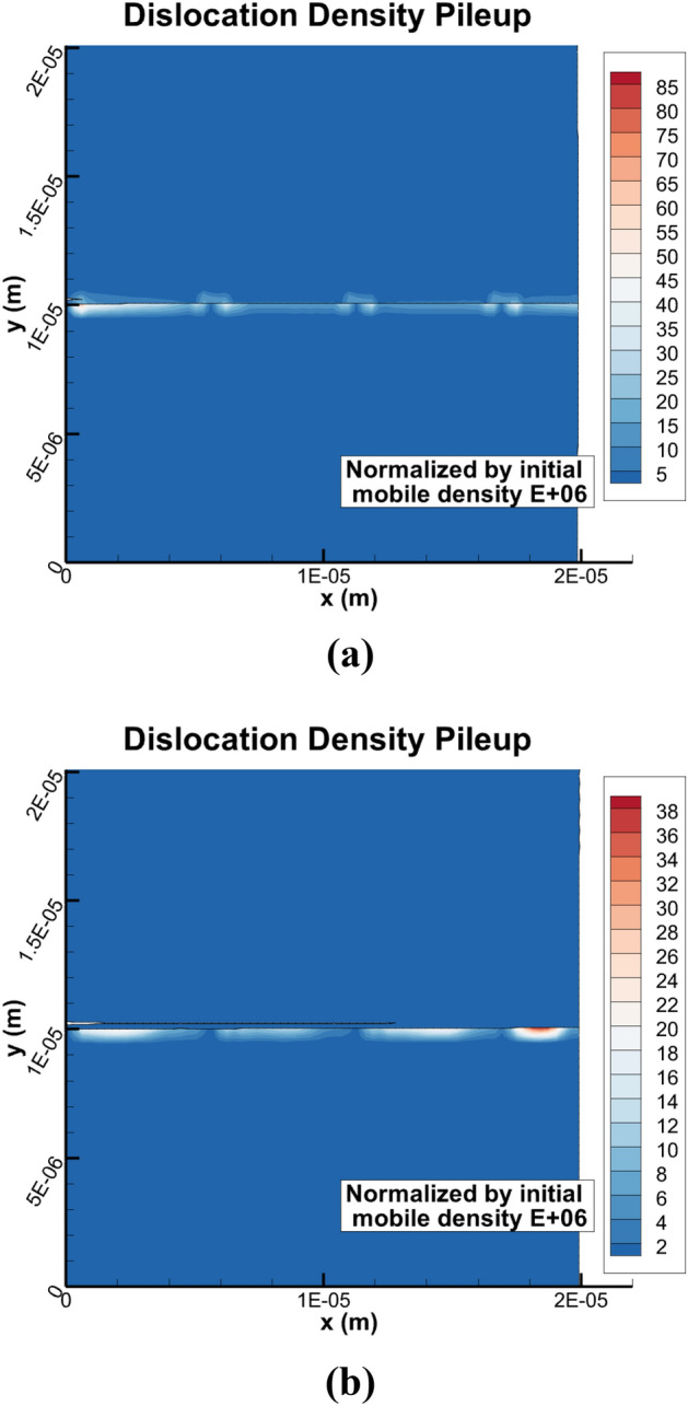
The total dislocation density pileups in (a) the low-angle model with the dominant slip system of , and in (b) the high angle model with the dominant slip system of .
In addition to the total dislocation density pileups, partial dislocation density pileups also play a critical role for fracture nucleation and propagation and dislocation-density interactions along the GB region. The most dominant interaction of total dislocation-densities in the pile-up region result in Hirth partial dislocation-densities, . The interactions are formed by slip systems 4 with 9 as
| 12 |
and for slip systems 3 with 10 as
| 13 |
Both interactions form Hirth partial dislocation-density pileups along both the low and high angle GBs at 0.8% nominal strain (Fig. 7a,b). For the Hirth partial dislocation-densities, for system , they are concentrated at the fracture nucleation sites for both the low and the high angle GBs. For the random LAGB case (Fig. 7a), the pileups attain a maximum value of at the crack front and reach an extremum at the fracture nucleation site with a value of . For the random HAGB case (Fig. 7b), the intergranular nucleated crack elongates as the pileups accumulate along the GB. The Hirth partial pileup attains the maximum value of . Because high angle GBs tend to nucleate fracture earlier than the low angle GBs do, the high angle GBs can only accumulate lower partial pileups than the low angle GBs. While Hirth partial dislocations within GBs is not as common as Shockley partials, it can occur as shown by the atomistic investigations32–34.
Fig. 7.

The normalized partial dislocation density pileups at 0.8% nominal strain in (a) the low-angle model with the dominant partials of 1/3[010], and in (b) the high angle model with the dominant partials of 1/3[010].
This behavior further underscores how partial and perfect dislocation density pileups play a significant role in fracture nucleation and propagation. The random HAGB nucleate fracture earlier than the random LAGB, such that the high angle GB unloads earlier than the low angle GB does. The HAGB requires less pileup dislocation-density to attain fracture nucleation than the LAGB. These predictions are consistent with experimental observations showing that HAGB can have less pile-ups than LAGB, but that they form at an earlier stage of deformation12–15.
Summary
This investigation focused on fundamental understanding how total and partial dislocation-density pileups and GB orientations and structures are intricately related to IG fracture for LAGB and HAGB for a Cu bicrystal. The GB orientations and structures were obtained from micropillar experiments, such that LAGBs and the HAGBs can be accurately represented and used for the modeling predictions. For the HAGB, there were fewer pileups and dislocation-density and stress accumulation at the crack front, and this resulted in cracks nucleating at lower nominal strains in comparison with the LAGB. The normal stresses and the dislocation-densities for the LAGB were higher than HAGB GB case. This indicates that the lower angle case could sustain higher stresses and dislocation-density accumulation before the onset of IG crack nucleation in comparison with the higher angle case. These microstructural mechanisms are the dominant mechanisms that lead to IG in f.c.c. bicrystals. This proposed approach can lead to accurate predictions and new fundamental understanding of how failure nucleates and evolves in polycrystalline metals and alloy.
Acknowledgements
This work is supported by the Laboratory Directed Research and Development (LDRD) Directed Research (DR) Program 20210036DR at Los Alamos National Laboratory and North Carolina State University. This work was performed, in part, at the Center for Integrated Nanotechnologies, an Office of Science User Facility operated for the U.S. Department of Energy (DOE) Office of Science. Los Alamos National Laboratory, an affirmative action equal opportunity employer, is managed by Triad National Security, LLC for the U.S. Department of Energy’s NNSA, under contract 89233218CNA000001.
Author contributions
All authors contributed equally to this manuscript.
Data availability
The datasets generated are available from the corresponding author upon request.
Competing interests
The authors declare no competing interests.
Footnotes
Publisher's note
Springer Nature remains neutral with regard to jurisdictional claims in published maps and institutional affiliations.
References
- 1.Kheradmand, N., Vehoff, H. & Barnoush, A. An insight into the role of the grain boundary in plastic deformation by means of a bicrystalline pillar compression test and atomistic simulation. Acta Mater.61, 7454–7465. 10.1016/j.actamat.2013.08.056 (2013). 10.1016/j.actamat.2013.08.056 [DOI] [Google Scholar]
- 2.Bond, D. M. & Zikry, M. A. Differentiating between intergranular and transgranular fracture in polycrystalline aggregates. J. Mater. Sci.53, 5786–5798. 10.1007/s10853-017-1847-2 (2018). 10.1007/s10853-017-1847-2 [DOI] [Google Scholar]
- 3.Miyamoto, H., Koga, H., Mimaki, T. & Hashimoto, S. Intergranular stress corrosion cracking of pure copper <111> tilt bicrystals. Interface Sci.9, 281–286. 10.1023/A:1015167030009 (2001). 10.1023/A:1015167030009 [DOI] [Google Scholar]
- 4.Robertson, I. M., Lee, T. C. & Birnbaum, H. K. Application of the in situ TEM deformation technique to observe how “clean” and doped grain boundaries respond to local stress concentrations. Ultramicroscopy40, 330–338. 10.1016/0304-3991(92)90130-C (1992). 10.1016/0304-3991(92)90130-C [DOI] [Google Scholar]
- 5.Guo, Y. Z., Li, F. D., Suo, T., Tang, Z. B. & Li, Y. L. A close observation on the deformation behavior of bicrystal copper under tensile loading. Mech. Mater.62, 80–89. 10.1016/J.MECHMAT.2013.04.001 (2013). 10.1016/J.MECHMAT.2013.04.001 [DOI] [Google Scholar]
- 6.Kiani, M. T. et al. In Situ TEM tensile testing of bicrystals with tailored misorientation angles. Acta Mater.224, 117505. 10.1016/J.ACTAMAT.2021.117505 (2022). 10.1016/J.ACTAMAT.2021.117505 [DOI] [Google Scholar]
- 7.Zhang, L., Lu, C. & Tieu, K. Atomistic simulation of tensile deformation behavior of ∑5 tilt grain boundaries in copper bicrystal. Sci. Rep.4, 5919–5919. 10.1038/srep05919 (2015). 10.1038/srep05919 [DOI] [PMC free article] [PubMed] [Google Scholar]
- 8.Xing, Z., Fan, H. & Kang, G. Molecular dynamics simulations on the intergranular crack propagation of magnesium bicrystals. Comput. Mater. Sci.210, 111058. 10.1016/j.commatsci.2021.111058 (2022). 10.1016/j.commatsci.2021.111058 [DOI] [Google Scholar]
- 9.You, X. et al. Intermediate temperature creep and deformation behavior of a nickel-based superalloy prepared by electron beam layer solidification. Scr. Mater.187, 395–401. 10.1016/j.scriptamat.2020.06.056 (2020). 10.1016/j.scriptamat.2020.06.056 [DOI] [Google Scholar]
- 10.Arcari, A., Zikry, M. A., Callahan, P. G., Horton, D. J. & Chen, M.-J. Modeling hydrogen diffusion in precipitation hardened nickel-based alloy 718 by microstructural modeling. Corros. Rev.10.1515/corrrev-2024-0013 (2024). 10.1515/corrrev-2024-0013 [DOI] [Google Scholar]
- 11.Granger, L., Chen, M.-J., Brenner, D. & Zikry, M. The challenges of modeling defect behavior and plasticity across spatial and temporal scales: A case study of metal bilayer impact. Metals12, 2036. 10.3390/met12122036 (2022). 10.3390/met12122036 [DOI] [Google Scholar]
- 12.Kim, Y. et al. Effect of a high angle grain boundary on deformation behavior of Al nanopillars. Scr. Mater.107, 5–9. 10.1016/j.scriptamat.2015.05.005 (2015). 10.1016/j.scriptamat.2015.05.005 [DOI] [Google Scholar]
- 13.Malyar, N. V., Micha, J. S., Dehm, G. & Kirchlechner, C. Size effect in bi-crystalline micropillars with a penetrable high angle grain boundary. Acta Mater.129, 312–320. 10.1016/j.actamat.2017.03.003 (2017). 10.1016/j.actamat.2017.03.003 [DOI] [Google Scholar]
- 14.Imrich, P. J., Kirchlechner, C., Motz, C. & Dehm, G. Differences in deformation behavior of bicrystalline Cu micropillars containing a twin boundary or a large-angle grain boundary. Acta Mater.73, 240–250. 10.1016/j.actamat.2014.04.022 (2014). 10.1016/j.actamat.2014.04.022 [DOI] [Google Scholar]
- 15.Chen, S. & Yu, Q. The role of low angle grain boundary in deformation of titanium and its size effect. Scr. Mater.163, 148–151. 10.1016/j.scriptamat.2018.10.054 (2019). 10.1016/j.scriptamat.2018.10.054 [DOI] [Google Scholar]
- 16.Chen, M.-J., Xie, D., Li, N. & Zikry, M. A. Dislocation-density evolution and pileups in bicrystalline systems. Mater. Sci. Eng. A.10.1016/j.msea.2023.144812 (2023). 10.1016/j.msea.2023.144812 [DOI] [Google Scholar]
- 17.Eidel, B. Crystal plasticity finite-element analysis versus experimental results of pyramidal indentation into (001) fcc single crystal. Acta Mater.59, 1761–1771. 10.1016/j.actamat.2010.11.042 (2011). 10.1016/j.actamat.2010.11.042 [DOI] [Google Scholar]
- 18.Chang, H.-J., Cordero, N. M., Déprés, C., Fivel, M. & Forest, S. Micromorphic crystal plasticity versus discrete dislocation dynamics analysis of multilayer pile-up hardening in a narrow channel. Arch. Appl. Mech.86, 21–38. 10.1007/s00419-015-1099-z (2016). 10.1007/s00419-015-1099-z [DOI] [Google Scholar]
- 19.Zheng, Z., Balint, D. S. & Dunne, F. P. E. Discrete dislocation and crystal plasticity analyses of load shedding in polycrystalline titanium alloys. Int. J. Plast.87, 15–31. 10.1016/j.ijplas.2016.08.009 (2016). 10.1016/j.ijplas.2016.08.009 [DOI] [Google Scholar]
- 20.Koslowski, M., Cuitiño, A. M. & Ortiz, M. A phase-field theory of dislocation dynamics, strain hardening and hysteresis in ductile single crystals. J. Mech. Phys. Solids50, 2597–2635. 10.1016/S0022-5096(02)00037-6 (2002). 10.1016/S0022-5096(02)00037-6 [DOI] [Google Scholar]
- 21.Spatschek, R., Brener, E. & Karma, A. Phase field modeling of crack propagation. Philos. Mag.91, 75–95. 10.1080/14786431003773015 (2011). 10.1080/14786431003773015 [DOI] [Google Scholar]
- 22.Shanthraj, P. & Zikry, M. A. Dislocation density evolution and interactions in crystalline materials. Acta Mater.59, 7695–7702. 10.1016/J.ACTAMAT.2011.08.041 (2011). 10.1016/J.ACTAMAT.2011.08.041 [DOI] [Google Scholar]
- 23.Zikry, M. A. An accurate and stable algorithm for high strain-rate finite strain plasticity. Comput. Struct.50, 337–350. 10.1016/0045-7949(94)90004-3 (1994). 10.1016/0045-7949(94)90004-3 [DOI] [Google Scholar]
- 24.Zikry, M. A. & Kao, M. Large-scale crystal plasticity computations of microstructural failure modes. Comput. Syst. Eng.6, 225–240. 10.1016/0956-0521(95)00024-T (1995). 10.1016/0956-0521(95)00024-T [DOI] [Google Scholar]
- 25.Kolar, H. R., Spence, J. C. H. & Alexander, H. Observation of moving dislocation kinks and unpinning. Phys. Rev. Lett.77, 4031–4034. 10.1103/PhysRevLett.77.4031 (1996). 10.1103/PhysRevLett.77.4031 [DOI] [PubMed] [Google Scholar]
- 26.Voisin, T. et al. In situ TEM observations of high-strain-rate deformation and fracture in pure copper. Mater. Today33, 10–16. 10.1016/j.mattod.2019.11.001 (2020). 10.1016/j.mattod.2019.11.001 [DOI] [Google Scholar]
- 27.Yan, Z. & Lin, Y. Lomer–Cottrell locks with multiple stair-rod dislocations in a nanostructured Al alloy processed by severe plastic deformation. Mater. Sci. Eng. A747, 177–184. 10.1016/j.msea.2019.01.066 (2019). 10.1016/j.msea.2019.01.066 [DOI] [Google Scholar]
- 28.de Koning, M., Miller, R., Bulatov, V. V. & Abraham, F. F. Modelling grain-boundary resistance in intergranular dislocation slip transmission. Philos. Mag. A82, 2511–2527. 10.1080/01418610208240050 (2002). 10.1080/01418610208240050 [DOI] [Google Scholar]
- 29.Shanthraj, P. & Zikry, M. A. Microstructurally induced fracture nucleation and propagation in martensitic steels. J. Mech. Phys. Solids61, 1091–1105. 10.1016/j.jmps.2012.11.006 (2013). 10.1016/j.jmps.2012.11.006 [DOI] [Google Scholar]
- 30.Velilla-Díaz, W., Pacheco-Sanjuan, A. & Zambrano, H. R. The role of the grain boundary in the fracture toughness of aluminum bicrystal. Comput. Mater. Sci.167, 34–41. 10.1016/j.commatsci.2019.05.031 (2019). 10.1016/j.commatsci.2019.05.031 [DOI] [Google Scholar]
- 31.Lim, S. J. & Huh, H. Ductile fracture behavior of BCC and FCC metals at a wide range of strain rates. Int. J. Impact Eng.159, 104050. 10.1016/j.ijimpeng.2021.104050 (2022). 10.1016/j.ijimpeng.2021.104050 [DOI] [Google Scholar]
- 32.Terentyev, D., Zhurkin, E. E. & Bonny, G. Emission of full and partial dislocations from a crack in BCC and FCC metals: An atomistic study. Comput. Mater. Sci.55, 313–321. 10.1016/j.commatsci.2011.11.010 (2012). 10.1016/j.commatsci.2011.11.010 [DOI] [Google Scholar]
- 33.Pang, W.-W., Zhang, P., Zhang, G.-C., Xu, A.-G. & Zhao, X.-G. Dislocation creation and void nucleation in FCC ductile metals under tensile loading: A general microscopic picture. Sci. Rep.4, 6981. 10.1038/srep06981 (2014). 10.1038/srep06981 [DOI] [PMC free article] [PubMed] [Google Scholar]
- 34.Aragon, N. K., Gravell, J. D. & Ryu, I. Dislocation interactions at the grain boundary in FCC bicrystals: An atomistically-informed dislocation dynamics study. Acta Mater.223, 117455. 10.1016/j.actamat.2021.117455 (2022). 10.1016/j.actamat.2021.117455 [DOI] [Google Scholar]
Associated Data
This section collects any data citations, data availability statements, or supplementary materials included in this article.
Data Availability Statement
The datasets generated are available from the corresponding author upon request.