

Abstract
Multiple harmonic generation is a key issue for coherence radiation generated by an electron beam modulated by the seeding laser. A new multiple harmonic generation scheme by combining the angular dispersion-induced microbunching (ADM) with the transverse echo effect, which can be easily generated by using pulsed dipoles, a pulsed quadrupole and a pulsed multipole, is investigated in a multi-bend achromatic storage ring. Simulation results demonstrate a triple of harmonic number compared to the case of pure ADM, making it possible to generate coherent extreme ultraviolet radiation in storage rings.
Subject terms: Lasers, LEDs and light sources; Free-electron lasers; Optics and photonics; High-harmonic generation; Nonlinear optics
Introduction
Multiple harmonic generation of a seeding laser is of great importance for both seeded free electron lasers (FEL) and storage ring-based coherent radiation. In the latter case, it becomes more challenging to get a high harmonic number due to the large energy spread of the stored beam and constraints on the ring twiss parameters. To overcome the limitations of large energy spread, a novel electron beam manipulation technique, the Angular Dispersion-Induced Microbunching (ADM) scheme, has been proposed in Ref.1,2 for the production of high harmonics. It takes advantage of the small vertical emittance of the electron beam in the storage ring to generate high harmonics of the seeding laser by coupling vertical phase space to longitudinal phase space with the assistance of the seeding laser3–7.
To enhance higher harmonics, cascaded ADM has been considered8; however, this approach introduces complexities to the storage ring design and needs an extremely long straight section to accommodate cascaded ADM insertion. Extra challenges may arise in a ring based on a multi-bend achromatic (MBA) lattice to maintain the small dynamic aperture without further reduction with the insertion.
Echo-Enabled Harmonic Generation (EEHG) in linac-based FEL has been proposed9,10 and successfully demonstrated11–16. EEHG applied to the storage ring has also been studied17–24, the most recent experimental demonstration at DELTA storage ring results got a very limited high harmonic number25. EEHG restricts its manipulation to the beam in the longitudinal phase space, and the large energy spread in the storage ring may be an issue for the storage ring-based EEHG. Although extremely high harmonic can be generated in simulations with EEHG, the required laser power is about orders of magnitude higher than ADM. Actually, investigations on echo effects in the transverse plane have been conducted since 199226,27 and have been successfully observed28,29, predating longitudinal phase space EEHG. The fundamental phenomenon underlying both EEHG and transverse echo is the same: the beam filamentation in phase space. However, the development of transverse echo in a storage ring requires hundreds or even thousands turns of evolution, making it feasible only in a hadron beam storage ring where radiation damping and quantum excitation are weak which prevents the smearing of fine phase space structure.
It was previously believed that transverse echo was impossible in an electron storage ring26–29. However, the situation may be changed when the MBA lattice becomes feasible. The MBA lattice exhibits strong nonlinear effects and large amplitude-dependent tune shifts (ADTS), which is one of the factors leading to a relatively small dynamic aperture. For such a large ADTS in an MBA lattice, a beam filament can develop quickly within few hundred turns before being destroyed by radiation damping and quantum excitation. Noting that the bunching factor of ADM depends on the vertical angular divergence, no matter for the entire beam or for a filament of the beam in vertical phase space, as long as it can be extracted. The bunching factor of ADM regarding to the transverse divergence is as follows1:
| 1 |
where is the n’th order of the Bessel function of the first kind, is the wave number of the seed laser, , is the energy spread of the electron beam and A is the energy modulation amplitude with respect to the electron beam energy spread. and are the dispersion and the momentum compaction generated in the dogleg respectively. is the vertical angular divergence.
To this end, this paper will explore the transverse echo effect in conjunction with ADM to generate high harmonics of the seed laser in an MBA storage ring. The paper is organized as follows: In section “Nonlinear effects and filamentation in MBA lattice”, we will discuss the nonlinear effects of MBA lattice and the diffusion phenomenon of electron beam after the action of pulsed dipoles. In section “Multiple harmonic generation by transverse echo effect”, we first utilize a pulsed quadrupole to manipulate the vertical phase space of the electron beam, and then analyze the high harmonics radiation brought about by the transverse echo effect. In section “Using a pulsed multipole to manipulate the phase space of the electron beam”, a pulsed sextupole or a pulsed octupole will be used to trim the vertical phase space of the electron beam, further enhancing the high harmonics of the seed laser. The discussions and conclusions will be given in section “Discussions and conclusions”.
Nonlinear effects and filamentation in MBA lattice
The storage ring employed in this paper is bought from Ref.3, which is a 3.5 GeV electron storage ring with a natural emittance of 20 pm·rad and a circumference of about 900 m. It should be noted that the lattice used in this paper is not a real machine but comes from a proposed machine. The ring is composed of 36 7BA higher-order achromat (HOA) unit cells. There are two long straight sections (LSS) with a length of about 30 m each, and the ADM section is arranged in one of the LSS opposite to the injection LSS. Figure 1 presents the layout of the entire storage ring with β-function in the injection LSS, and also includes a schematic representation of the longitudinal positions of the pulsed dipoles, pulsed quadrupole, and pulsed sextupole/octupole that will be used in subsequent simulations.
Fig. 1.
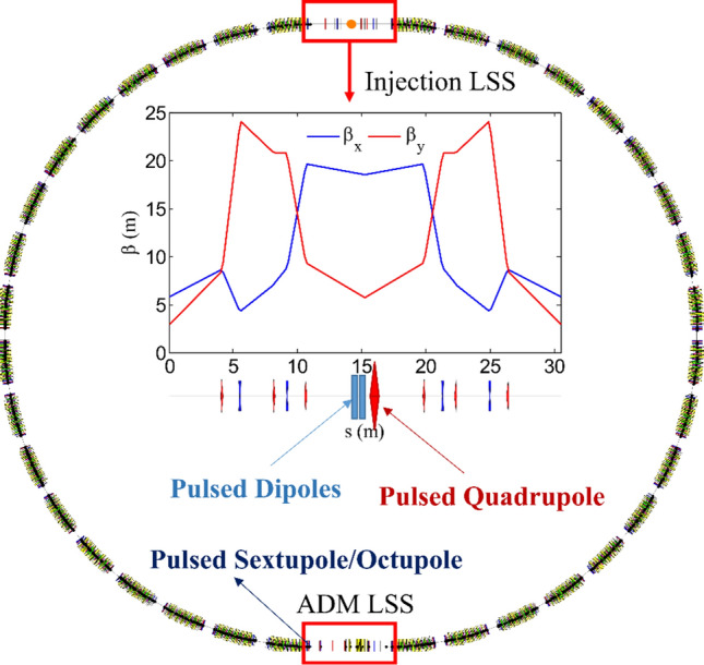
Layout of the entire storage ring along with β-function in the injection LSS, and schematic representation of the longitudinal positions of the pulsed dipoles, pulsed quadrupole, and pulsed sextupole/octupole.
Despite the consideration of nonlinear phase cancellation relationship within a single cell and between multiple cells during the linear design of this MBA lattice30,31, the overall nonlinear effect remains significant. The values of ADTS, second-order chromaticity, and third-order chromaticity of this MBA storage ring are shown in Table 1.
Table 1.
ADTS and high-order chromaticity parameters.
| Parameter | Symbol | Unit | Value |
|---|---|---|---|
| ADTS | dνx/dJx | m−1 | 2.25 × 10⁵ |
| dνx/dJy | m−1 | −1.39 × 10⁶ | |
| dνy/dJy | m−1 | −5.77 × 10⁶ | |
| Second-order chromaticity | dνx/dp2 | – | −1.01 × 10³ |
| dνy/dp2 | – | 1.55 × 10² | |
| Third-order chromaticity | dνx/dp3 | – | −5.88 × 10⁴ |
| dνy/dp3 | – | 5.13 × 10³ |
Figure 2 demonstrates the tune shift as the initial vertical amplitude varies. It can be observed that when the vertical amplitude changes within a range of 0.5 mm, the horizontal tune changes by approximately 0.07, while the vertical tune changes by approximately 0.14. The significant changes in vertical tune shift with the variation of vertical amplitude are consistent with the ADTS in Table 1.
Fig. 2.
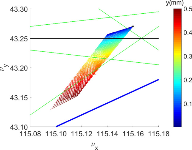
Tune shift versus the initial vertical amplitude along with a resonance diagram. The star in the figure represents the betatron tune (115.16, 43.27) of the storage ring.
The transverse echo effect takes advantage of the filamentation of the electron beam to manipulate its vertical phase space through the action of pulsed dipoles and a pulsed quadrupole. By clustering as many electrons as possible within a narrow range of vertical divergence coordinates y′, we can reduce the vertical angular divergence of the sliced electron beam and thereby increase its high harmonics radiation.
In the following, we will demonstrate the excellent performance of this scheme through simulation using the ELEGANT code32. A Gaussian distributed electron beam bunch was randomly initialized at the injection point, assumed to be at the center of the injection LSS, with parameters shown in Table 2, where H and V denote the horizontal and vertical directions, respectively. The ADM section has a total of 7 vertical dipoles to fulfill ADM conditions and achieve achromat in the vertical plane, which generates vertical dispersion, and the radiator is placed at a position where the vertical dispersion is approximately 11.8 mm (compared with the average horizontal dispersion at the horizontal bends in the arc of this MBA storage ring is 1.36 mm), resulting in a vertical emittance of 20 pm·rad.
Table 2.
Main parameters employed in the simulations.
| Parameter | Symbol | Unit | Value |
|---|---|---|---|
| Beam energy | E | GeV | 3.5 |
| Relative energy spread | – | 0.103% | |
| Geometric horizontal emittance | pm·rad | 20 | |
| Geometric vertical emittance | pm·rad | 20 | |
| Rms bunch length | mm | 1.8 | |
| Beta function in the injection LSS center (H, V) | (βx, βy) | m | (18.6, 5.7) |
| Revolution time | T0 | μs | 3.0 |
| Vertical damping time | τy | ms | 13.7 |
| Laser wavelength | nm | 266 |
The simulation used 50,000 particles. The electron beam first passes through a pulsed dogleg, which consists of two pulsed dipoles connected by a drift. The integral bending angle of one pulsed dipole is 0.526 mrad··meter, and the length of the drift between them is 0.2 m, resulting in a vertical offset in the vertical plane of 10σy (σy = 10.51 μm), and the distribution of electron beam in the vertical plane is shown in Fig. 3a. The blue points in Fig. 3a show the initial electron beam distribution in the vertical plane, while the red points show the distribution after kicked by pulsed dipoles.
Fig. 3.

Phase space of beam in the vertical plane at the injection LSS center: (a) blue points denote initial Gaussian distribution, while red points denote offset 10σy by pulsed dipoles; (b) tracking130 turns after pulsed dipoles (c) tracking 400 turns after pulsed dipoles; (d) tracking 600 turns after pulsed dipoles.
The larger the offset, the faster the filamentation develops. However, the amplitude should remain within the dynamic aperture to ensure no particle loss, including during subsequent manipulation. In making these compromises, the offset of the kick is chosen to be 10σy.
The electron beam was tracked in the storage ring, we found that when the electron beam circulates 130 turns, the head and tail of the electron beam in the vertical phase space are nearly connected, as shown in Fig. 3b. From Fig. 3c,d, we can see that the diffusion phenomenon of the electron beam is very serious, and the fine structure will soon disappear after around 600 turns due to the radiation damping and quantum excitation. It should be noted that in the simulations of Fig. 3 we did not include the intra-beam scattering (IBS) effect. The growth time of the IBS can be calculated by the Bjorken-Mtingwa’s formula33,34, which is 131.9 ms for a beam current of 150 mA. , therefore, the IBS effect is negligible in the simulation. We have compared the high harmonic results of 130 turns and 400 turns, which shows that 130 turns case is better, therefore, we choose the phase space at the 130th turn as the starting point for subsequent phase space manipulation. As shown in Fig. 3b, the vertical angular divergence of the sliced beam indicated in the red rectangular box is 0.59 μrad, while the initial electron beam's vertical angular divergence is 1.85 μrad as shown in Fig. 3a. The vertical angular divergence of the electron beam is reduced to about one-third of its original value. According to Eq. (1), this would be greatly beneficial for enhancing the high harmonics radiation if the beam density projected on the y′ coordinate can be peaked in a narrow area. To achieve this additional manipulation is needed.
The severe filamentation phenomenon is also depicted in Fig. 10a of Ref.3. However, it is mainly caused by the energy modulation in the ADM section through longitudinal to transverse coupling, which is slightly different from the manipulation discussed in this paper and is not adopted to produce transverse echo in this paper.
Fig. 10.
(a) The longitudinal phase space distribution of the electron beam at the radiator after pulsed octupole and (b) the corresponding bunching factor.
Multiple harmonic generation by transverse echo effect
The electron beam in Fig. 3b encounters a small pulsed quadrupole kick with an integrated strength of 0.2 m−1, the vertical phase space of the electron beam changes to the red points shown in Fig. 4. The main parameters of all pulse magnets used in this paper are summarized in Table 3. The storage ring has a total of 1500 buckets, and the pulse width of all pulse magnets is selected to be 500 ns. The pulsed magnets kick 250 bunches for the phase space manipulation each time. The kick strength and pulse width are feasible without encountering significant technical challenges.
Fig. 4.
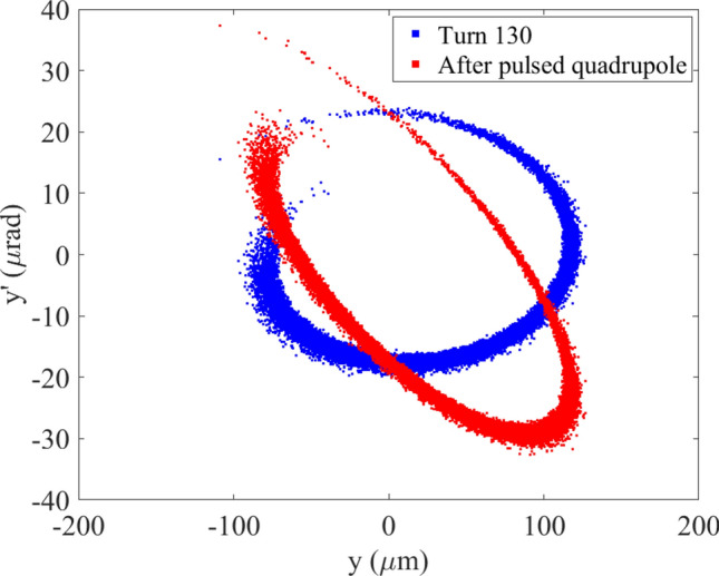
The phase space of the electron beam in the vertical plane at the 130th turn at the injection LSS center after the pulsed dipoles (blue points) and then after a pulsed quadrupole (red points).
Table 3.
The main parameters of pulse magnets.
| Parameter | Symbol | Unit | Value |
|---|---|---|---|
| Integrated strength of pulsed dipoles | mrad··m | 0.526 | |
| Integrated strength of pulsed quadrupole | m−1 | 0.2 | |
| Integrated strength of pulsed sextupole | m−2 | 30 | |
| Integrated strength of pulsed octupole | m−3 | 1.3 × 10⁵ | |
| Pulse width of all pulse magnets | tpulse | ns | 500 |
The electron beam after passing through the pulsed quadrupole was tracked in the storage ring. At 5.5 turns, (0.5 turn is starting from the midpoint of injection LSS to the first vertical dipole B0 in ADM section), the vertical phase space distribution at the entrance of the first vertical dipole B0 is shown in Fig. 5a. Figure 5b shows the statistical distribution projected to y′ coordinate. As can be seen from Fig. 5b, the vertical divergence coordinate y′ of the electron beam is mainly concentrated around − 4.26 μrad. This narrow range of electron beams serves as the primary source for achieving microbunching using the ADM scheme.
Fig. 5.
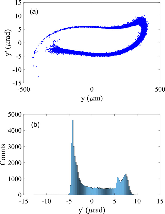
(a) The vertical phase space at the entrance of the first vertical dipole B0 after 5.5 turns and (b) Statistical distribution projected to y′ coordinates.
Here, we’d like to compare the traditional transverse echo with the phenomenon presented here. For traditional transverse echo, the time intervals between two kicks and the last kick to the observation moment should be equal. With such a setup, transverse dipole (centroid) oscillations will be observed by the beam position monitor (BPM). Since BPM cannot detect the phase space structure inside the beam, the traditional transverse echo may be under tighter constraints to be observed. For the beam manipulation in this paper, some kinds of structures in phase space will soon be developed before centroid oscillations occurs, thus the kick time interval and kick to the radiation moment are not necessarily to be equal. Though centroid oscillations have not occurred in this case which can be expected if further tracking is performed, we still call it transverse echo as the basic manipulation method and the underlying physics is similar.
Based on the electron beam distribution in Fig. 5, we conducted a simulation using the designed ADM transport line in Ref.3. The interaction between the laser and the electron beam was done in an undulator with a very small energy modulation amplitude of . The longitudinal phase space distribution of the electron beam at the radiator is shown in Fig. 6a, and the corresponding bunching factor is shown in Fig. 6b. Within a range of laser wavelengths, the electron beam forms two micro-bunches, with one being denser and defined as the main micro-bunch and the other as the sub micro-bunch. This is mainly due to the fact that there are two peaks in Fig. 5b. The sub micro-bunches are not at the exact middle of the main micro-bunches disrupted the harmonic pattern resulting in a lower bunching factor for a lower harmonic number compared to Ref.3, however the harmonic number can be increased to exceed 15.
Fig. 6.
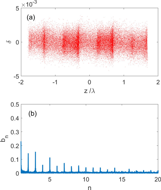
(a) The longitudinal phase space distribution of the electron beam at the radiator and (b) the corresponding bunching factor.
Using a pulsed multipole to manipulate the phase space of the electron beam
In section III, we have already analyzed the increasing of the bunching factor due to the distorted distribution of the electron beam in the vertical phase space. In this section, we add a pulsed multipole to further optimize the vertical phase space distribution of the electron beam, so that as many electrons as possible have their y’ distribution centered around -4.26 μrad, to increase the high harmonics radiation of the electron beam. We will correct the vertical phase space distribution of the electron beam in two different cases, which are by a pulsed sextupole or by a pulsed octupole kick. The following is a presentation of the simulation results for each case.
Pulsed sextupole Kick
The electron beam, after having passed through a pulsed quadrupole, is then passed through a pulsed sextupole with an integral strength of 30 m−2 after 5.5 turns in the storage ring, whose phase space in the vertical plane is shown in Fig. 7a. The blue points represent the phase space distribution before the pulsed sextupole, and the red points represent the phase space distribution after the pulsed sextupole. Figure 7b shows the statistical distribution of the vertical divergence coordinate y′ of the electron beam after pulsed sextupole. It can be seen that the number of electrons distributed between 5 to 8 μrad in the y′ coordinate is reduced, while the electrons close to − 4.26 μrad are concentrated. We conducted ADM simulation tracking on electron beam after passing through pulsed sextupole, obtaining the longitudinal phase space distribution at the radiator and the corresponding bunching factor as shown in Fig. 8. It can be seen that the bunching factor increased somewhat. The main micro-bunches in Fig. 8 are strengthened while the sub micro-bunches are weakened accordingly.
Fig. 7.

(a) The vertical phase space at the entrance of the first vertical dipole B0 before and after pulsed sextupole; (b) Statistical distribution projected to y' coordinates after pulsed sextupole.
Fig. 8.

(a) The longitudinal phase space distribution of the electron beam at the radiator after pulsed sextupole and (b) the corresponding bunching factor.
Pulsed octupole kick
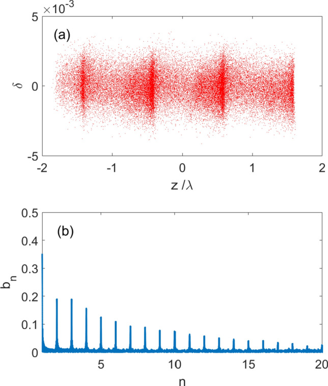
In this section, we replace the pulsed sextupole with a pulsed octupole to trim the vertical phase space of the electron beam. If the electron beam in Fig. 5a passes through a pulsed octupole with an integrated strength of 1.3 × 10⁵ m−3, its vertical phase space will be changed to Fig. 9a. The blue points represent the phase space distribution before the pulsed octupole, and the red points represent the phase space distribution after the pulsed octupole. Figure 9b shows the statistical distribution of the electrons in coordinate y′ after pulsed octupole. We can see that more electrons are concentrated around − 4.4 μrad. Similar to the previous simulation, we conducted ADM simulation tracking on the electron beam after passing through the pulsed octupole, obtaining the longitudinal phase space distribution at the radiator and the corresponding bunching factor as shown in Fig. 10. It can be seen that the bunching factor of the electron beam can be further increased, and the electron beam is basically clustered into main micro-bunches, while the sub micro-bunches disappear.
Fig. 9.
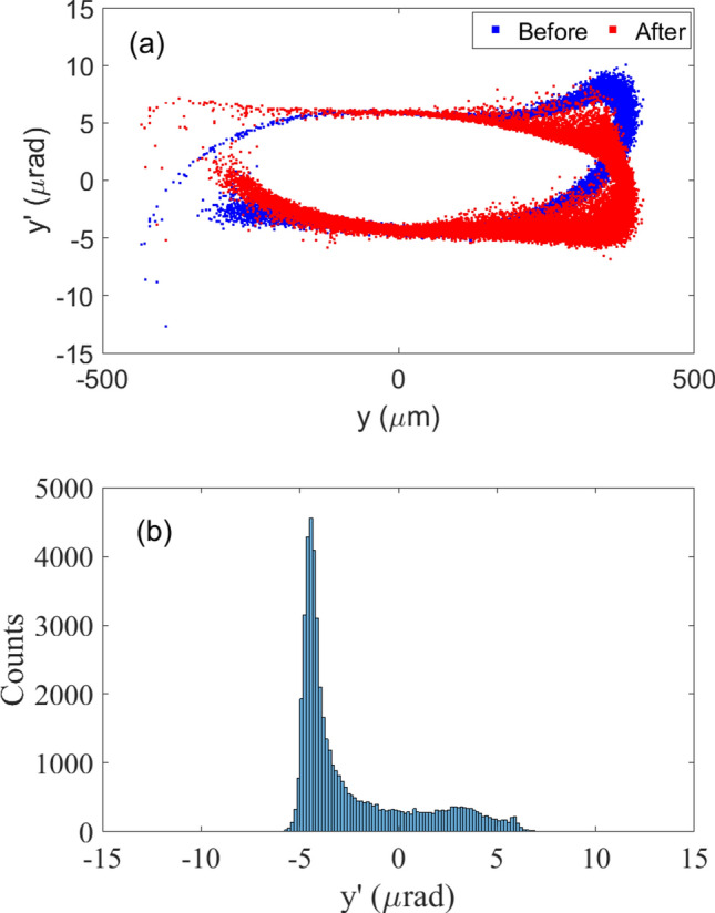
(a) The vertical phase space at the entrance of first vertical dipole B0 before and after pulsed octupole; (b) Statistical distribution projected to y′ coordinates after pulsed octupole.
It can be observed from Figs. 8 and 10 that the bunching factor of the electron beam is improved significantly in the case of using pulsed octupole. Compared with the results in Fig. 3 of Ref.3, the harmonic number can be tripled with the transverse echo effect as shown in Fig. 11. The 20th harmonic of the seed laser can be observed in this case, making it possible to generate coherent extreme ultraviolet (EUV) radiation in the storage ring.
Fig. 11.

The comparison of the bunching factor, where the blue line represents the results from Fig. 3 in Ref.3 and the red line represents bunching factors after the action of pulsed octupole.
Discussions and conclusions
The increase in horizontal emittance caused by the phase space manipulation is negligible. However, the increase in the vertical projected emittance due to phase space filamentation and energy modulation is significant. The vertical emittance of the electron beam after manipulation through the pulsed octupole in Fig. 9a is about 514 pm, which increases to 727 pm after modulation through the ADM. After emitting coherent radiation, the electron beam circulates in the storage ring and returns to its equilibrium state due to radiation damping. The evolution of the vertical projected emittance with the number of turns is shown in Fig. 12, from which it can be seen that the vertical emittance of the electron beam reaches a maximum value of 1.43 nm at about 90 turns, and then gradually decreases by radiation damping. The circumference of the storage ring is approximately 900 m, resulting in a revolution frequency of 333.33 kHz for the electron beam. After 20,000 turns, as illustrated in Fig. 12, the vertical emittance reaches equilibrium state, indicating that the repetition rate of a single bunch is 16.67 Hz. There are in total 1,500 buckets in the ring, 300 of which are filled with 1.5 nC-bunches for this scheme to produce high power radiation. The corresponding total repetition rate of the coherent radiation is 5 kHz.
Fig. 12.
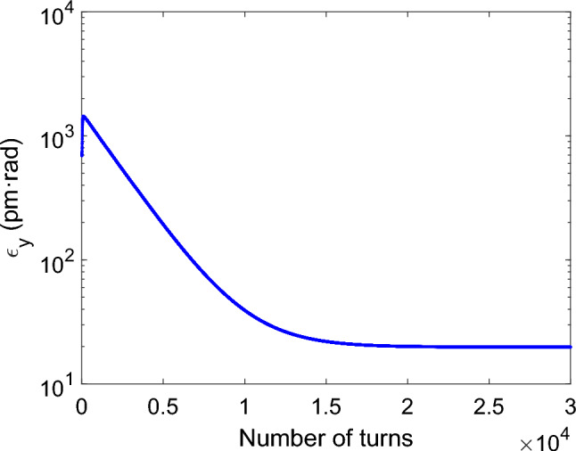
The vertical projected emittance evolves with the number of turns after the electron beam is manipulated by the pulsed octupole and a single energy modulation.
It should be noted that the operation of the proposed scheme in single bunch mode at 5 kHz will result in 300 modulated bunches being equidistantly spread out over the 20,000 turns. Beamline stations dedicated to this scheme will achieve synchrotron radiation with high coherence. However, the brightness seen by other users will be reduced. The average vertical emittance and energy spread seen by other users are 196 pm rad and 0.11%, respectively. For a two-meter long in-vacuum undulator (IVU) with a peak magnetic field of 0.9 T and a period length of 20 mm, the spectral brightness at 2.4 keV calculated with the SPECTRA code35 changed from the original 1.68 × 10²¹ phs/s/mm2/mrad2/0.1%BW to 5.16 × 10²⁰ phs/s/mm2/mrad2/0.1%BW.
Owing to the strong nonlinear effect of the MBA lattice, the transverse filamentation effect was observed in simulation in an electron storage ring. Compared to the initial ADM method, the combination of three transverse kicks (categorized as transverse echo) with the ADM results in a triple increase in harmonic number, making it possible to generate coherent EUV radiation in storage rings without encountering significant technical challenges.
In a real machine, determining the optimal number of turns for the electron beam to pass between the actions of pulsed dipoles and pulsed quadrupoles is crucial. This optimal number of turns is a key factor in the generation of multiple harmonics radiation and depends on specific machine parameters such as beam energy, damping time, ADTS, and dynamic aperture. However, observing filamentation in phase space, while straightforward in simulations, presents a significant challenge in practice. Therefore, the optimal number of turns will be determined through a trial-and-error process in the experiment. The pulsed magnets must have the capability to adjust the delay over a wide range of turns. Overall, the proposed scheme is robust, ensuring the successful generation of multiple harmonic radiation.
To meet the needs of different users, ultra-fast kickers with a pulse width for instance of 20 ns will be employed. These ultra-fast kickers are not overly aggressive, allowing only 10 bunches to produce multiple harmonic coherent radiations. As a result, specific users will target these 10 bunches, while other users will utilize the radiated light from the remaining bunches, similar to the femto-slicing scheme in a storage ring36,37.
Although the harmonic number is not very high in this paper, it is limited by the relatively large vertical emittance and the constrained vertical beta function at the ADM section. A dedicated design can significantly increase the harmonic number, such as reducing the beam energy to reduce the energy spread and vertical emittance, and increasing the vertical beta function at the entrance of the first vertical dipole in the ADM section.
Acknowledgements
This work was supported by the National Natural Science Foundation of China (No. 12305161).
Author contributions
B. Jiang conceived the design of the proposed scheme. C. Li performed the simulations. C. Li, B. Jiang and Y. Zhang co-wrote the paper.
Data availability
The simulated results during the current study are available from the corresponding author on reasonable request.
Competing interests
The authors declare no competing interests.
Footnotes
Publisher's note
Springer Nature remains neutral with regard to jurisdictional claims in published maps and institutional affiliations.
References
- 1.Feng, C. & Zhao, Z. A storage ring based free-electron laser for generating ultrashort coherent EUV and X-ray radiation. Sci. Rep.7, 4724 (2017). 10.1038/s41598-017-04962-5 [DOI] [PMC free article] [PubMed] [Google Scholar]
- 2.Jiang, B. et al. A synchrotron-based kilowatt-level radiation source for EUV lithography. Sci. Rep.12, 3325 (2022). 10.1038/s41598-022-07323-z [DOI] [PMC free article] [PubMed] [Google Scholar]
- 3.Li, C., Feng, C. & Jiang, B. Extremely bright coherent synchrotron radiation production in a diffraction-limited storage ring using an angular dispersion induced microbunching scheme. Phys. Rev. Accel. Beams23, 110701 (2020). 10.1103/PhysRevAccelBeams.23.110701 [DOI] [Google Scholar]
- 4.Lu, Y. et al. Generating coherent and ultrashort X-ray pulses via HHG-seeding in storage rings. J. Synchrotron Rad.29, 347 (2022). 10.1107/S1600577521013382 [DOI] [PMC free article] [PubMed] [Google Scholar]
- 5.Wang, X. et al. Angular dispersion enhanced prebunch for seeding ultrashort and coherent EUV and soft X-ray free-electron laser in storage rings. J. Synchrotron Rad.26, 677 (2019). 10.1107/S1600577519002674 [DOI] [PubMed] [Google Scholar]
- 6.Li, C. et al. Lattice design for angular dispersion enhanced microbunching in storage rings. JINST16, P03004 (2021). 10.1088/1748-0221/16/03/P03004 [DOI] [Google Scholar]
- 7.Li, C. et al. Lattice design for an improved angular dispersion-induced microbunching scheme. JINST17, P11020 (2022). 10.1088/1748-0221/17/11/P11020 [DOI] [Google Scholar]
- 8.Lu Y., Feng, C. & Wang, D. A novel scheme based on angular dispersion-induced microbunching mechanism for harmonic generation in storage ring. In Proceedings of the 14th International Particle Accelerator Conference (IPAC2023), Venice, Italy, TUPL089, 1935–(1938).
- 9.Stupakov, G. Using the beam-echo effect for generation of short-wavelength radiation. Phys. Rev. Lett.102, 074801 (2009). 10.1103/PhysRevLett.102.074801 [DOI] [PubMed] [Google Scholar]
- 10.Xiang, D. & Stupakov, G. Echo-enabled harmonic generation free electron laser. Phys. Rev. ST Accel. Beams12, 030702 (2009). 10.1103/PhysRevSTAB.12.030702 [DOI] [Google Scholar]
- 11.Xiang, D. et al. Demonstration of the echo-enabled harmonic generation technique for short-wavelength seeded free electron lasers. Phys. Rev. Lett.105, 114801 (2010). 10.1103/PhysRevLett.105.114801 [DOI] [PubMed] [Google Scholar]
- 12.Zhao, Z. et al. First lasing of an echo-enabled harmonic generation free-electron laser. Nat. Photon.6, 360–363 (2012). 10.1038/nphoton.2012.105 [DOI] [Google Scholar]
- 13.Feng, C. et al. Coherent extreme ultraviolet free-electron laser with echo-enabled harmonic generation. Phys. Rev. Accel. Beams22, 050703 (2019). 10.1103/PhysRevAccelBeams.22.050703 [DOI] [Google Scholar]
- 14.Hemsing, E. et al. Echo-enabled harmonics up to the 75th order from precisely tailored electron beams. Nat. Photon.10, 512–515 (2016). 10.1038/nphoton.2016.101 [DOI] [Google Scholar]
- 15.Rebernik-Ribič, P. et al. Coherent soft X-ray pulses from an echo-enabled harmonic generation free-electron laser. Nat. Photon.13, 555–561 (2019). 10.1038/s41566-019-0427-1 [DOI] [Google Scholar]
- 16.Yu, L. H. & Shaftan, T. Towards coherent X-ray free-electron lasers. Nat. Photon.13, 513–515 (2019). 10.1038/s41566-019-0495-2 [DOI] [Google Scholar]
- 17.Yang, X. et al. Optimization of echo-enabled harmonic generation toward coherent EUV and soft X-ray free-electron laser at NSLS-II. Sci. Rep.12, 9437 (2022). 10.1038/s41598-022-13702-3 [DOI] [PMC free article] [PubMed] [Google Scholar]
- 18.Yang, X. et al. Toward fully coherent soft x-ray free-electron laser via echo-enabled harmonic generation in fourth generation synchrotron light sources. Rev. Sci. Instrum.93, 113101 (2022). 10.1063/5.0100488 [DOI] [PubMed] [Google Scholar]
- 19.Yang, X. et al. Twin-pulse seeding enables pump-probe capabilities in the EUV to soft X-ray spectrum at synchrotron light sources. Sci. Rep.13, 5261 (2023). 10.1038/s41598-023-32496-6 [DOI] [PMC free article] [PubMed] [Google Scholar]
- 20.Yang, X. et al. Toward a fully coherent tender and hard X-ray free-electron laser via cascaded EEHG in fourth-generation synchrotron light sources. J. Synchrotron Rad.26, 30 (2023). [DOI] [PMC free article] [PubMed] [Google Scholar]
- 21.Hwang, J.-G. et al. Generation of intense and coherent sub-femtosecond X-ray pulses in electron storage rings. Sci. Rep.10, 10093 (2020). 10.1038/s41598-020-67027-0 [DOI] [PMC free article] [PubMed] [Google Scholar]
- 22.Khan, S. et al. Generation of ultrashort and coherent synchrotron radiation pulses at DELTA. Synchrotron Radiat. News26(3), 25–29 (2013). 10.1080/08940886.2013.791213 [DOI] [Google Scholar]
- 23.Liu, W. H., Zhou, G. Q. & Jiao, Y. Generating femtosecond coherent X-ray pulses in a diffraction-limited storage ring with the echo-enabled harmonic generation scheme. Nucl. Sci. Tech.29, 143 (2018). 10.1007/s41365-018-0476-z [DOI] [Google Scholar]
- 24.Gao, W. W., Li, H. T. & Wang, L. Preliminary study of EEHG-based superradiant undulator radiation at the HLS-II storage ring. Chin. Phys. C41, 078101 (2017). 10.1088/1674-1137/41/7/078101 [DOI] [Google Scholar]
- 25.Büsing, B., Held A. et al. Preparatory experimental investigations in view of EEHG at the DELTA storage ring. In Proceedings of the 40th International Free Electron Laser Conference (FEL2022), Trieste, TUP70, 313–316.
- 26.Stupakov, G. V. Echo effect in hadron colliders. SSC Report SSCL-579, July 1992.
- 27.Stupakov, G. & Kauffmann, S. Echo effect in accelerators. SSC Report SSCL-587, September 1992.
- 28.Arduini, G. et al. Transverse beam echo measurements on a single proton bunch at the SPS. SL-Note-2000-048 MD.
- 29.Fischer, W., Satogata, T. & Tomas, R. Measurement of transverse echoes in RHIC. In Proceedings of 2005 Particle Accelerator Conference (PAC2005), Knoxville, Tennessee, 1955–1957.
- 30.Verdier, A. Resonance free lattices for A.G. Machines. In Proceedings of 1999 Particle Accelerator Conference (PAC1999), New York, USA, 398–400.
- 31.Cai, Y. et al. Ultimate storage ring based on fourth-order geometric achromats. Phys. Rev. Accel. Beams15, 054002 (2012). 10.1103/PhysRevSTAB.15.054002 [DOI] [Google Scholar]
- 32.Borland, M. elegant: A flexible SDDS-compliant code for accelerator simulation. In Proceedings of the 6th International Computational Accelerator Physics Conference (ICAP 2000), Darmstadt, Germany, LS-287 (2000).
- 33.Bjorken, J. D. & Mtingwa, S. K. Intrabeam scattering. Part. Accel.13, 115 (1983). [Google Scholar]
- 34.Bane, K. L. F. A simplified model of intrabeam scattering. In Proceedings of 2002 European Particle Accelerator Conference (EPAC2002), Paris, France, 1443–1445.
- 35.Tanaka, T. Major upgrade of the synchrotron radiation calculation code SPECTRA. J. Synchrotron Rad.28, 1267 (2021). 10.1107/S1600577521004100 [DOI] [PubMed] [Google Scholar]
- 36.Khan, S. et al. Femtosecond undulator radiation from sliced electron bunches. Phys. Rev. Lett.97, 074801 (2006). 10.1103/PhysRevLett.97.074801 [DOI] [PubMed] [Google Scholar]
- 37.Schoenlein, R. W. et al. Generation of femtosecond pulses of synchrotron radiation. Science287, 2237 (2000). 10.1126/science.287.5461.2237 [DOI] [PubMed] [Google Scholar]
Associated Data
This section collects any data citations, data availability statements, or supplementary materials included in this article.
Data Availability Statement
The simulated results during the current study are available from the corresponding author on reasonable request.