

Abstract
Chemokine receptor CXCR4 is involved in diverse diseases. A comparative study was conducted on CXCR4 embedded in a POPC lipid bilayer binding with CXCL12 in full and truncated forms, hBD-3 in wildtype, analog, and mutant forms based on in total 63 µs all-atom MD simulations. The initial binding structures of CXCR4 with ligands were predicted using HADDOCK docking or random-seed method, then μs-long simulations were performed to refine the structures. CXCR4&ligand binding structures predicted agree with available literature data. Both kinds of ligands bind stably to the N-terminus, extracellular loop 2 (ECL2), and ECL3 regions of CXCR4; the C2-C3 (K32-R38) region and occasionally the head of hBD-3 bind stably with CXCR4. hBD-3 analogs with Cys11-Cys40 disulfide bond can activate CXCR4 based on the Helix3-Helix6 distance calculation, but not other analogs or mutant. The results provide insight into understanding the dynamics and activation mechanism of CXCR4 receptor binding with different ligands.
Subject terms: Molecular modelling, Biophysical chemistry
The chemokine receptor CXCR4 is involved in cancers and diverse diseases, however, molecular details surrounding the binding of different ligands to this receptor remain incomplete. Here, the authors study the binding and interaction between CXCR4 with CXCL12 and hBD-3 in different forms, and find that both ligands can bind with CXCR4 at the same site, and analogs of hBD-3 with a Cys11-Cys40 disulfide bond can activate CXCR4.
Introduction
Chemokines are a family of signaling peptides secreted by cells (or called cytokines) that have molecular masses in the range of 8 to 10 kDa. They can be divided into CXC and CC chemokines based on the spacing of cysteine residues in the amino terminal region, and on the overall sequence identity. The chemokine receptors, a part of the large family of 7-stranded transmembrane (TM) G protein coupled receptors (GPCRs), are activated by chemokine ligands with a range of specificities and affinities that result in a complicated network of interactions. Chemokine receptors together with their ligands can regulate the migration of many different cell types, most notably leukocytes1–3. Thus they play a role in immune surveillance, inflammation, and development. The chemokine receptor 4 (CXCR4) contributes to inflammatory diseases and cancer4–6. CXCR4 overexpression is known in more than 20 human tumor types, including breast cancer, ovarian, prostate, esophageal, melanoma, neuroblastoma, and renal cell carcinoma7. CXCR4 also functions as a co-receptor for HIV viral entry into host cells8. It has chemotactic activity by chemo-attracting B- and T-cells in response to a concentration gradient of its natural chemokine ligand CXCL129,10. The experimental structures of CXCR4 (PDB ID 3ODU4) and the truncated CXCL12 (t-CXCL12) (which has the first four residues chopped, with PDB ID 3GV311) and antagonist hBD-3 (PDB ID 1KJ612) are shown in Fig. 1. CXCL12, also known as stromal cell-derived factor 1 alpha (SDF-1α), can bind with CXCR4 as an agonist, and activate CXCR4 signaling which is primarily coupled through Gi proteins. However, when the first four residues are chopped, the t-CXCL12 is potentially an antagonist for CXCR413. The interactions between CXCL12 and CXCR4 comprise a biological axis that affects the growth, angiogenesis and metastasis of cancer, thus the complex is a promising target for cancer therapy as it supports migration, proliferation, and survival of cancer cells.
Fig. 1. CXCR4, hBD-3 and CXCL12 structures.

CXCR4 structural model in sideview (a) and topview (b), with the N-terminus (abbreviated as N-term), extracellular loop region (ECL) 1 to 3, TM helix 1–7, and C-terminus (abbreviated as C-term) labeled, and orthosteric pocket pointed out. The structures of hBD-3 wildtype (c) and t-CXCL12 (d) are also shown, with the disulfide bonds forming residues shown in yellow, the N-term, C-term, and important regions pointed out. Although RES 1-26 of CXCR4 is chopped in (a), the CRS1 site is the receptor with the residue number from 1 to 34 (the N-terminus shown in red in (a)), CRS2 site involves the orthosteric pocket (the TM regions pointed out by an arrow) and ECLs of the receptor (ECL1 in blue, ECL2 in cyan, and ECL3 in magenta), while CRS1.5 includes the continuous interface between CRS1 and CRS2 on CXCR4 for the binding of ligand with CXCR4.
In addition to binding with CXCL12, CXCR4 also can bind with human β defensin type 3 (hBD-3)14. hBD-3 is a cationic cysteine-rich 45-residue peptide15. It belongs to the human innate immune system. It is mainly produced by epithelial cells, and has a broad-spectrum of antimicrobial activities16–18. hBD-3 has 6 cysteine residues which can form 3 pairs of intra-molecular disulfide bonds in the pattern of C1–C5, C2–C4, C3–C6. Under reducing conditions the disulfide bonds can break in a specific order19 and form a topologically linear analog. Feng et al.20 found that hBD-3 can antagonize CXCR4 function on T cells and promote receptor internalization in the absence of activation, and the ability of hBD-3 to inhibit CXCL12 and CXCR4 interaction is either by blocking CXCL12 binding to CXCR4 or antagonizing CXCL12-induced Ca2+ mobilization. Such kind of ability of hBD-3 is correlated with the presence of hBD-3 cysteine residues, specific surface-distributed cationic residues, the electrostatic properties and availability of both hBD-3 termini. Although Feng et al.20 showed that hBD-3 mostly functions as an antagonist for CXCR4, removing the disulfide bonds on hBD-3 diminishes its antagonist function. Thus, the hBD-3 analogs which have 1 to 3 disulfide bonds removed could potentially behave as an agonist to CXCR4. But neither the exact binding interfaces of hBD-3 in wildtype and analog forms with CXCR4, nor their constitutive dynamics and structures binding with CXCR4 in molecular details are known.
Tamamis and Floudas21 predicted the binding structure of multiple CXCL12 molecules (with different PDB IDs (2KEE and 2J7Z) and the residue numbers from 1 to 68) with CXCR4 (with residue number from M1NT to S352CT) by docking, molecular dynamics (MD) simulations and binding free energy calculations. They found that CXCL12 N-terminus should bind with CXCR4 transmembrane (TM) domain, and the central 24-50 residues on CXCL12 interact with the upper N-terminal domain of CXCR4. Up to now, the complex structures of CXCR4 bound with four ligands have been experimentally determined, including the small molecule IT1t, the cyclic peptide CVX15, and the human herpesvirus-8 chemokine vMIP-II4,13 which function as antagonists, and CXCL1222 which functions as an agonist. The binding structure of CXCR4 with CXCL12 has been solved using cryoEM recently22. Mostly, small molecules were found to bind with CXCR4 on the orthosteric binding pocket (as indicated by an arrow in Fig. 1). While these structures provide insight into the inactive or active state conformations of the receptors, they fail to provide much information about the receptor conformations adopted upon agonist binding or other antagonists binding. Since CXCR4 is a therapeutic target for different kinds of diseases, it is important to understand how novel ligands interact with CXCR4 and how those ligands achieve their different functions. The CXCR4 receptor has been shown to form a homodimer or heterodimer constitutively and upon ligand binding using different experimental methods23–26. However, the functional mechanism of dimerization has not been fully understood yet. A recent work by Qin et al.13 found that CXCR4 may also function in a monomer form. So in this study, CXCR4 monomer bound with different ligands were investigated.
The goal of this study is to predict the binding and interaction of hBD-3 in different forms with CXCR4 using a combined simulation strategy. Since experimental data is available for CXCL12 binding and interaction with CXCR4, simulations were conducted for both kind of ligands binding with CXCR4. With the assumption that exploring the structure and interaction mechanism of hBD-3 and CXCL12 binding with CXCR4 embedded inside lipid membrane could supply new insight understanding the functional mechanism of CXCR4, long-term molecular dynamics simulations have been performed on CXCR4 in both free (apo) state and ligand bound state. Since unbound experimental structures of CXCR4, hBD-3, and CXCL12 are available, we applied different protein-protein docking programs to explore different orientations of ligand relative to CXCR4 (random-seed method and HADDOCK docking) and predicted worth-investigating different initial binding structures of CXCR4 with different ligands based on the experimental unbound structures. The complexes from the docking calculations were then embedded in phospholipid bilayers and subjected to microsecond-long all-atom MD simulations to predict the most probable bound structures of the complexes, as well as the binding structure and dynamics of the protein-CXCR4 complexes. Besides that, microsecond-long simulations were conducted on full-length CXCL12 bound with full-length CXCR4 initiated from Tamamis et al.’s prediction21, and a brief simulation on CXCL12 bound with CXCR4 based on the cryoEM structure (PDB ID 8U4O)22. The study plans to further understand the relationship between their binding structures and dynamics with molecular details, through a comparative study on CXCR4 binding with an agonist (CXCL12), a potential antagonist (t-CXCL12), an antagonist (hBD-3 wt) and multiple potential agonists (hBD-3 analogs and mutant). It was found that CXCL12 and hBD-3 in different forms bind with CXCR4 at the same site. Activation of CXCR4 by CXCL12 and hBD-3 analogs which have Cys11-Cys40 disulfide bond was observed based on the CXCR4 Helix3-Helix6 distance calculation, but not by other hBD-3 analogs or mutant.
Results
Simulation strategy, initial structures, and systems investigated
Initial structures
To predict the binding and interaction of hBD-3 in different forms with CXCR4, a combined simulation strategy was applied. Since experimental data is available for CXCL12 binding and interaction with CXCR4, simulations were conducted on both kind of ligands binding with CXCR4. Both full-length CXCR4, and CXCR4 with the first 26 residues chopped were investigated in this project, since the head region of CXCR4, which corresponds to the first 26 residues of CXCR4, is not well-defined (with PDB ID 3ODU in which CXCR4 only has residues from 27 to 3194 in this work following Qin et al.13). The t-CXCL12 has (the PDB ID of 3GV3) the residue numbers from 5 to 67, and hBD-3 has 45 residues (the PDB ID of 1KJ612, and the sequences for CXCR4, t-CXCL12 and hBD-3 are shown in Supplementary Table S1). There are experimental data available on this CXCR4 (with the first 26 residues chopped) from Qin et al.13, on CXCL12 from Crump et al.27, and on hBD-3 from Feng et al.14, with the structure of CXCR4 in sideview and topview shown in Fig. 1a, b; and hBD-3 wildtype and t-CXCL12 structures shown in Fig. 1c, d. In order to predict the contribution of first 4 residues on CXCL12 and the head and tail of CXCR4 to the binding of CXCL12 with CXCR4 and activity, the full length CXCL12 and full length CXCR4 were studied as well with the initial structures from the Tamamis prediction21 (the full length sequences for CXCL12 and CXCR4 are shown in Supplementary Table S1). In order to compare simulation result with cryoEM detected binding structure of CXCR4 bound with CXCL12 (PDB ID of 8U4O), one simulation was also conducted starting from this structure. In order to predict the effect of redox condition and mutation of hBD-3 on the binding with CXCR4, the initial structures of hBD-3 analogs (in total 7) and one mutant were predicted (based on 500 ns NAMD simulations each starting from the wildtype structure, and the last structures are shown in Supplementary Fig. S1). Overall, hBD-3 wildtype and analog structures are consistent with the major fluctuations in the N-terminal and second loop regions (figures not shown).
Docking methods
In our simulation strategy, in total two methods were applied to predict the initial binding structures of hBD-3/t-CXCL12 with CXCR4 before microsecond-long MD simulations were conducted. One is the targeted HADDOCK docking and the other is the random-seed method (the details are shown in the “Methods” section). HADDOCK docking program28,29 was used to predict initial binding structures for hBD-3 in wildtype, different analog forms and mutant, t-CXCL12 in complex with CXCR4. The hBD-3 analog and mutant structures were predicted after 500 ns simulations each (details shown in the “Methods” section, and structures shown in Supplementary Fig. S1a–i). These ligand structures and CXCR4 crystal structure were used in HADDOCK docking. Since it is known that the binding sites on CXCR4 are on its N-terminal and the extracellular regions, we performed targeted docking. The entire N-terminal and extracellular loop regions of CXCR4 were selected as the target binding sites in the docking. Since having ligand reaching the orthosteric pocket of CXCR4 is necessary for its function27, and there is experimental structure information available for CXCL12 bound with CXCR413 and hBD-3 bound with CXCR414, we selected the best HADDOCK docking complexes from the top scored list that satisfied binding interface information from the available experimental results4,14,21.
In order to catch all possible correct binding interfaces, the random-seed method was applied as well, which can implement the binding sites or binding interface possibly missed by the HADDOCK docking. In the random-seed method, the ligand was placed above the receptor with a distance between the center of the ligand and the lipid bilayer surface of no less than 35 Å to avoid bias from the initial ligand structure and allow the ligand to approach CXCR4 freely. Since electrostatic interaction is important for hBD-3 binding with receptors and lipid28,30, and hBD-3 has been found to bind with receptors and lipids on the β2 sheet region31,32, all the initial structures were oriented to let the β2 sheet of hBD-3 face the receptor and the lipid bilayer. The t-CXCL12 was aligned to let the N-terminus and β sheet region face the CXCR4 and lipid membrane as suggested by Tamamis and Floudas21. In addition, the hBD-3/t-CXCL12 monomer binding with CXCR4 simulation was repeated for six times, each starting from the same initial structure but with a different random seed in order to explore different possible binding sites between ligands and CXCR4 receptor. A total of seven runs for each kind of ligand were performed for up to 300 ns using the NAMD program in the random-seed method. Only the bound structures from stable simulations (no dissociation or shifting on the binding interface in 300 ns) were selected as the stable initial structures from the random-seed method.
Systems investigated
Based on above docking strategies, two hBD-3-CXCR4 simulations predicted stable complex structures from the random-seed method (named hbd3-wt-rs1, hbd3-wt-rs2), one from HADDOCK docking method (named hbd3-wt-hd), and one t-CXCL12-CXCR4 simulation (named CXCL12-rs1) were selected to run microsecond-long simulations, besides the simulation on CXCR4 in the free state (named free-CXCR4 at 310 K) as shown in Supplementary Table S2. To check the effect of temperature on the dynamics of CXCR4, another two simulations, named free-CXCR4-300K and free-CXCR4-323K simulations for CXCR4 in the free state at 300 K and 323 K respectively, were also conducted with the same initial configuration as the free-CXCR4 (at 313 K) simulation. Since the disulfide bonding status of hBD-3 can affect its chemotactic activity14, we also set up the initial structures of hBD-3 analogs bound with CXCR4. In total, seven hBD-3 monomers in different analog forms, corresponding to the number of disulfide bonds from 0 (most reduced form) to 2 shown in Supplementary Table S3 and one hBD-3 mutant, were docked with CXCR4 using both HADDOCK and the random-seed methods and simulations were conducted on them. The jobs predicted from HADDOCK docking program are named hbd3-la-hd, analog#1-hd, analog#2-hd, analog#3-hd, analog#4-hd, analog#5-hd, analog#6-hd, hbd3-3ser-hd. Because the hbd3-wt-rs1 simulation shows a conserved complex structure during 2.4 us, its initial structure from the random-seed method was used as the initial structure for different hBD-3 analogs by modifying the disulfide bonding status according to that shown in Supplementary Table S3. These jobs are named analog#1-rs, analog#2-rs, analog#3-rs, analog#4-rs, analog#5-rs, analog#6-rs. Besides that, ligand in free state simulations were conducted as well, named free-hbd3-wt for hBD-3 wildtype and free-CXCL12 for t-CXCL12 in the solvent system only. Furthermore, three simulations initiated from the Tamamis et al. predicted full-length CXCl12 bound with CXCR4 structure were set up, including CXCL12 bound with full-length CXCR4, with CXCR4 having residues from 1 to 26 chopped, and with CXCR4 having residues from 1 to 26 or from 320 to 352 chopped. In total, 27 microsecond-long simulations were conducted and the total simulation time is more than 63 μs. In order to compare the prediction with available experimental data, one short MD simulation was conducted on cryoEM initiated structure of CXCR4 bound with CXCL12 (8U4O job).
RMSD and RMSF results show that hBD-3/CXCL12 can bind with CXCR4 stably
RMSD results
Based on simulation trajectories, the root-mean-square deviation (RMSD) of the CXCR4 receptor and the peptidic ligands were calculated over the simulation time based on the coordinates of protein backbone heavy atoms including CA, C, and N after aligning the trajectories to the crystal structure of CXCR4 and ligands respectively, with results shown in Supplementary Figs. S2 and S3 and Table 1. The details of calculating ligand RMSD are shown in “Methods” section. Since the CXCR4 head (residues M1NT-E26NT) and tail region (residues L3017.52 to S352CT as listed in Supplementary Table S1) are very flexible, only the seven helices region of CXCR4 (residues C28NT-I3007.51) was included in RMSD calculation for the receptor (Figs. S2 and S3 and Table 1). All the long-term MD simulations reached well-equilibrated states, especially during the second-half of the long-term simulations (as shown in Figs. S2 and S3). 8U4O job shows the most conserved structures for CXCR4 and CXCL12 during 150 ns simulation (as the smallest RMSD of CXCR4 helix region shown in Table 1 and the smallest RMSD of CXCR4 in helix region vs. time result shown in Supplementary Fig. S3). The reason could be the strong binding formed between CXCR4 and CXCL12 as shown in the binding energy result section. In fact, CXCR4 in free state is more dynamic because it has multiple loop regions, especially the extracellular loop regions, which are very flexible. The binding of ligand to its extracellular loop regions can significantly decrease the flexibility of the loop regions of CXCR4. Since the helix regions are connected by the loop regions, it is not surprising to see that the helices of CXCR4 become less dynamic in the bound form. However, in this project, only seven helix regions of CXCR4 were included in the calculation, with the RMSD results shown in Table 1. Because of that, the difference in RMSD of CXCR4 in bound state and free state is not that significant.
Table 1.
RMSD of CXCR4 (unbound or bound), peptidic ligands hBD-3 or CXCL12, the number of hydrogen bonds formed between CXCR4 and ligands, H3–H6 distance, score, and the activity level predicted using the converged second-half of long-term simulations
| Job name | RMSDCXCR4 (Å) | RMSDligand (Å) | Numhbonds | H3–H6 (Å) (score) | Activity level |
|---|---|---|---|---|---|
| free-CXCR4 | 4.0 ± 0.2 | N/A | N/A | 13.5 (90%) | Active |
| CXCR4-300K | 4.3 ± 0.5 | N/A | N/A | 8.8 (7%) | Intermediate |
| CXCR4-323K | 3.6 ± 0.2 | N/A | N/A | 11.8 (59%) | Partially active |
| free-hbd3-wt | N/A | 6.8 ± 1.6 | N/A | N/A | N/A |
| free-CXCL12 | N/A | 4.0 ± 0.7 | N/A | N/A | N/A |
| CXCL12-hd | 3.2 ± 0.4 | 4.2 ± 0.4 | 3.9 ± 1.8 | 7.1 (0%) | Inactive |
| CXCL12-rs1 | 3.3 ± 0.2 | 4.2 ± 0.3 | 3.8 ± 1.6 | 8.8 (7%) | Intermediate |
| CXCL12-f | 3.3 ± 0.3 | 3.8 ± 0.8 | 4.5 ± 2.1 | 10.6 (38%) | Partially active |
| CXCL12-nh | 3.2 ± 0.3 | 4.2 ± 0.9 | 3.2 ± 1.7 | 8.2 (0%) | Inactive |
| CXCL12-nht | 2.8 ± 0.3 | 4.7 ± 0.9 | 3.6 ± 1.9 | 13.1 (83%) | Active |
| hbd3-wt-rs1 | 2.8 ± 0.1 | 5.4 ± 0.4 | 3.4 ± 1.6 | 8.6 (3%) | Inactive |
| hbd3-wt-rs2 | 3.6 ± 0.2 | 6.3 ± 0.2 | 4.1 ± 1.9 | 8.6 (4%) | Inactive |
| hbd3-wt-hd | 3.3 ± 0.2 | 4.2 ± 0.3 | 4.5 ± 1.6 | 7.6 (0%) | Inactive |
| hbd3-la-hd | 3.7 ± 0.3 | 6.5 ± 0.3 | 3.9 ± 1.7 | 7.8 (0%) | Inactive |
| analog#1-hd | 3.2 ± 0.2 | 3.2 ± 0.1 | 2.9 ± 1.5 | 7.1 (0%) | Inactive |
| analog#1-rs | 3.2 ± 0.1 | 7.2 ± 0.7 | 2.7 ± 1.5 | 7.4 (0%) | Inactive |
| analog#2-hd | 3.1 ± 0.2 | 5.3 ± 1.0 | 3.6 ± 1.7 | 10.4 (35%) | Partially active |
| analog#2-rs | 3.6 ± 0.2 | 8.3 ± 0.6 | 4.6 ± 1.7 | 10.8 (42%) | Partially active |
| analog#3-hd | 3.4 ± 0.1 | 2.9 ± 0.4 | 4.2 ± 1.7 | 9.2 (14%) | Intermediate |
| analog#3-rs | 4.0 ± 0.2 | 4.8 ± 0.3 | 5.0 ± 1.9 | 10.5 (36%) | Partially active |
| analog#4-hd | 3.0 ± 1.5 | 8.5 ± 1.0 | 4.5 ± 2.4 | 7.4 (0%) | Inactive |
| analog#4-rs | 3.2 ± 0.2 | 7.6 ± 1.4 | 6.7 ± 2.1 | 8.3 (0%) | Inactive |
| analog#5-hd | 3.8 ± 0.2 | 3.5 ± 0.2 | 4.0 ± 2.0 | 8.3 (0%) | Inactive |
| analog#5-rs | 3.8 ± 0.2 | 8.9 ± 0.7 | 4.7 ± 1.9 | 8.2 (0%) | Inactive |
| analog#6-hd | 3.2 ± 0.2 | 2.8 ± 0.7 | 4.5 ± 1.9 | 8.6 (4%) | Intermediate |
| analog#6-rs | 3.1 ± 0.2 | 6.4 ± 1.0 | 3.6 ± 1.7 | 9.1 (12%) | Intermediate |
| hbd3-3ser-hd | 3.4 ± 0.3 | 6.2 ± 1.3 | 4.1 ± 1.8 | 7.5 (0%) | Inactive |
| 8U4O job | 1.2 ± 0.2 | 1.8 ± 0.4 | 7.5 ± 2.0 | 14.1 (100%) | Active |
RMSF results
Calculating the Root Mean Squared Fluctuation (RMSF) of CXCL12, hBD-3, and CXCR4 in bound and unbound states in different MD simulations (method shown in “Methods” section), the results are shown in Figs. 2 and S4. As can be seen in Fig. 2a, the head and tail of CXCL12 are more flexible than the central region. The CXCL12 molecule in 8U4O job, including its N-terminal region, has a lower flexibility than other jobs. The reason should be that the N-terminus of CXCL12 binds deeper into the orthosteric pocket of CXCR422 and a stronger binding formed between them than other jobs, thus both the ligand and the receptor are less dynamic. All MD simulations resulted in CXCL12 inside the orthosteric pocket with the ligand head bound with the EC loop (see the most probable structure shown in "Most probable structures comparison" subsection). Figure 2b shows that overall the head of hBD-3 is much more flexible than the tail except for hbd3-wt-rs2 and analog#3-hd and analog#3-rs jobs, while hBD-3 molecules in analog#4-hd and analog#4-rs, and part of hbd3-la-hd have much higher RMSF than other jobs. Comparing the RMSF of hBD-3 from different simulations demonstrated its dependence on the disulfide bonding status. The linear analog of hBD-3 and analog#4 (has only 1 disulfide bond) are more flexible than the wildtype, mutant, and other analog forms. The hBD-3 wt (hBD-3 in wildtype) in the free state (in solvent) has a similar flexibility to its bound state in the β1 to β2 region (residue number from 10 to 35). The head of hBD-3 wt bound with CXCR4 has a similar flexibility to that of free hBD-3 in solvent in our previous work as well19.
Fig. 2. RMSF of CXCR4 and ligands.

RMSF of CXCL12 (a), hBD-3 (b) and CXCR4 (c) in free and bound states based on microsecond-long simulations. The secondary structure of CXCL12, hBD-3 and CXCR4 corresponding to the residue numbers on X-axis are shown on the top of each sub-figure (a)–(c) individually. Residues important for the activation of CXCR433 are pointed out by up-side triangles in (c).
The RMSF of full-length CXCR4 is much higher than that of CXCR4 without the head region, and also higher than CXCR4 without the tail region. This suggests that the head and tail can increase the flexibility of the helix regions on CXCR4. CXCR4 with both the head and tail chopped has very similar RMSF in both the free and bound states with different ligands overall. The CXCR4 molecule in the 8U4O job which also has the head and tail regions chopped, has the lowest flexibility among all CXCR4 jobs. Residues important for the activation of CXCR4 as identified by ref. 33 from experimental work, are pointed out by upside triangles in Fig. 2c. Those residues usually have very low RMSF as shown.
Number of hydrogen bond result shows that CXCR4 forms similar amount of hydrogen bonds with CXCL12 and hBD-3, and has a negatively charged core
The calculated number of hydrogen bonds formed between the ligand and CXCR4 during the simulations is presented in Table 1 (with a plot for the change in the number of hydrogen bonds with simulation time shown in Supplementary Fig. S5). Both ligands form an average of 3 to 6 hydrogen bonds with the CXCR4 receptor, with the analog#4-rs simulation having a larger amount of hydrogen bonds, and the 8U4O job has the highest number of hydrogen bonds formed between CXCL12 and CXCR4 (7.5 ± 2.0). Analyzing the residue pairs forming hydrogen bonds (the residue pairs and duration (or called occupancy percentage) information are shown in Tables S4 and S5), it was observed that in total 9 out of 25 residues on CXCR4 have been found to form hydrogen bonds compared to other ligands as observed in the experimental structures by Qin et al.13 or Wu et al.4 (see Supplementary Tables S4 and S5). The key residues on t-CXCL12 forming hydrogen bonds with CXCR4 are L5, R8, S6, R12, K27, R41, R47, which are at the head and central (RES 24-50) region of t-CXCL12. The key residues on CXCR4 forming hydrogen bonds with t-CXCL12 are: D1935.32, D2626.58, E268ECL3, Q2727.23, E2777.28, E2887.39, which are on ECL2, ECL3, and helices forming the orthosteric pocket, such as TM5 to TM7. In full-length CXCL12 bound with CXCR4 simulations, K1 on CXCL12 forms hydrogen bonds with E2887.39 on CXCR4 consistently. These findings agree with results from Tamamis and Floudas21. The 8U4O job has consistent hydrogen bonds formed between the head of CXCL12 and CXCR4, which have a much higher occupancy thus are less dynamic than other CXCR4-ligand complexes. Analyzing the key residues on hBD-3 which form hydrogen bonds with CXCR4, it was observed that the residues on the head, G1, T5, Q7, K8, R12, and on the second loop region, K32, R36, R38 are important, while critical residues on CXCR4 are on the N-terminus, ECL2/ECL3 region and the orthosteric pocket (R301.24, D972.63, D181ECL2, D187ECL2, D1935.32, D2626.58, E321.26, E2887.39, E268ECL3, Y190ECL2). These findings agree with experimental results reported in Feng et al.14. Interestingly, it was found that all residues on the ligands are hydrogen bond donors while residues on CXCR4 are hydrogen bond acceptors, except one pair in hbd3-wt-rs2 simulation, and one pair in hbd3-3ser-hd simulation, in which the residue on hBD-3 is an acceptor while the residue on CXCR4 is a donor (see Tables S4 and S5). CXCR4 has a negatively charged core around the orthosteric binding pocket which favors its binding with positively charged ligands. The location of residues forming hydrogen bonds on the binding interface of the complex is shown on the most probable complex structures in the next section. Thus, the hydrogen bond results suggest that our simulation prediction on the binding structure of ligand with CXCR4 should be reasonable.
Most probable structures predicted and distance map result
Most probable structures comparison
The most probable structures from the microsecond-long MD simulations are shown in Fig. 3 and Supplementary Figs. S6–S8 (Left). The binding structure of full-length CXCL12 with CXCR4 (CXCL12-f job) shown in Fig. 3g aligns with the structure from cryoEM detected structure by Saotome et al.22 demonstrated in Supplementary Fig. S8 (Right). An RMSD of 3.0 Å was achieved for those two structures with the main deviations contributed by the loop regions. The upper-half of the TM helices of GPCR can form a cavity, usually referred to as the orthosteric pocket, as shown in Fig. 1a. To be consistent with the definition in others’ work27,34,35, the binding interfaces of CXCR4 with ligands have been specified into CRS1, CRS2, and CRS1.5 binding sites. As shown in Fig. 1, the CRS1 site includes the N-terminus of the receptor (residue numbers from 1 to 34 with the N-terminus shown in red), CRS2 site involves the orthosteric pocket (TM region indicated by an arrow) and ECLs of the receptor (ECL1 (in blue), ECL2 (in cyan), and ECL3 (in magenta)), while CRS1.5 includes the continuous interface between CRS1 and CRS2 for the binding of ligand with CXCR4. Based on such a definition, the binding sites of 23 simulations are presented in Table 2. The CXCL12-f simulation predicted the most probable structure on both CRS1.5 and CRS2 binding sites, while CXCL12-nh and CXCL12-nht predicted the CRS2 binding site.
Fig. 3. The most probable structures of ligand-CXCR4 complexes.

The most probable structures of t-CXCL12 (shown in red) bound with CXCR4 from HADDOCK initiated structure (a), from random-seed initiated structure (b), hBD-3 (shown in orange) bound with CXCR4 from random-seed method in hbd3-wt-rs1 job (c), from hbd3-wt-rs2 job (d), from HADDOCK initiated (e), and from hBD-3 linear analog starting from HADDOCK (hbd3-la-hd job) (f), CXCL12 bound with CXCR4 (g), with CXCR4 having RES 1-26 chopped (h), with CXCR4 having both RES 1-26 and RES 320-352 chopped (i) during microsecond-long simulations. The key residues contribute to the hydrogen bonds formation are labeled, with residues on ligand labeled in black and the top three residues based on occupancy ranking shown in blue lines and others in skyblue, while residues on CXCR4 labeled in dark red and the top three residues shown in magenta lines and others in pink. The CXCR4 is oriented to show the TM4 and TM5 (labeled) in the front.
Table 2.
The binding site on CXCR4 and the ligand’s region closest to the orthosteric pocket of CXCR4 based on the most probable complex structures of different simulations, with the stable structures’ binding site and region italicized
| Job name | Binding site; Region | Job name | Binding site; Region |
|---|---|---|---|
| CXCL12-hd | CRS2; N-term | CXCL12-rs1 | CRS1.5; L1 |
| hbd3-wt-rs1 | CRS1.5; C2-C3 | hbd3-wt-rs2 | CRS2; N-term |
| hbd3-wt-hd | CRS2; C2-C3 | CXCL12-f | CRS1.5,CRS2; N-term,C2-C3 |
| analog#1-hd | CRS2; C2-C3 | CXCL12-nh | CRS2; C2-C3 |
| analog#2-hd | CRS1.5; C2-C3 | CXCL12-nht | CRS2; C2-C3 |
| analog#3-hd | CRS1.5; N-term | analog#1-rs | CRS1.5; C2-C3 |
| analog#4-hd | CRS2; N-term | analog#2-rs | CRS1.5; C2-C3 |
| analog#5-hd | CRS1.5; α1 | analog#3-rs | CRS1.5; C2-C3 |
| analog#6-hd | CRS2; C2-C3 | analog#4-rs | CRS2; C2-C3 |
| hbd3-3ser-hd | CRS2; N-term | analog#5-rs | CRS2; C2-C3 |
| hbd3-la-hd | CRS2; N-term | analog#6-rs | CRS1.5; C2-C3 |
| 8U4O job | CRS2; N-term, C2-C3 |
N-term is the abbreviation of N-terminus.
The HADDOCK docking initiated simulations almost always predicted the CRS2 binding sites, except for several simulations including CXCL12-rs1, hbd3-wt-rs1, analog#2-hd and analog#5-hd which are on the CRS1.5 binding site. On the other hand, the random-seed method initiated simulations always predicted the CRS1.5 binding site, except for hbd3-wt-rs2, analog#4-rs, and analog#5-rs jobs.
Additionally, it was found that the disulfide bonding status can affect the binding structures of hBD-3 with CXCR4. The reason is that disulfide bonds can constrain the structure of hBD-3, and the structures of hBD-3 in wildtype and different analog forms can be quite different. Thus, multiple hBD-3 ligands were predicted to bind with CXCR4 on the CRS2 binding site, as shown in Table 2. In summary, hBD-3 can reach the orthosteric pocket of CXCR4 through the head or C2-C3 (K32-R38) region. hBD-3 wildtype and analog#4 (only disulfide bond C23-C41 not broken) can have conserved binding with CXCR4 through both the head and C2-C3 region, while less conserved binding structure was predicted for CXCR4 bound with hBD-3 analog#2 (disulfide bond C18-C33 broken) and analog#3 (disulfide bond C23-C41 broken).
The MM-GBSA binding free energies are shown in Supplementary Table S6, and the energy change during the simulation time is presented in Supplementary Fig. S9. The binding interaction energies in hbd3-wt-rs2 and hbd3-wt-hd are both low since both are on the CRS2 binding sites. Similarly, the predicted structures from both analog#4-rs and analog#4-hd are on the CRS2 site, and both have comparable low interaction energies. The most stable binding structures predicted are italicized in Table 2, those are on CRS2 or CRS2 plus CRS1.5 binding sites. Considering that HADDOCK docking initiated simulations mostly predicted a binding site on CRS2, that suggests that HADDOCK docking initiated simulations predicted more stable binding structures than the random-seed method mostly does. Interestingly, the binding energy predicted for the 8U4O job is almost four times of other jobs. That agrees with the deeper insertion of the N-terminus of CXCL12 into orthosteric pocket of CXCR4, and a much stronger binding between CXCR4 and CXCL12.
Distance map results
Calculating the average distances between residues on the ligand and on CXCR4 during the simulation time, and projecting the combined distances on the sequence of CXCR4 or the ligand in the color map from red to white (with red representing a residue pair distance of 0 Å, and white for 10 Å and above), the results for 6 CXCL12 simulations are shown in Fig. 4a, for 17 hBD-3 jobs in Fig. 4b, and for all 23 jobs on CXCR4 in Fig. 4c. As can be seen, in general, the head and central β2 to β3 regions of CXCL12 (see Fig. 1) bind to CXCR4 (as listed in Table 2). In the full-length CXCL12 simulations (CXCL12-f, CXCL12-nh, CXCL12-nht), the head of CXCL12 consistently binds with CXCR4, although the central β2 to β3 region may not. This is consistent with findings from Crump et al.27 who found that CXCL12 should have the N-terminus reaching the orthosteric pocket of CXCR4. Those findings agree with the binding regions from the 8U4O job as shown. Thus, all CXCL12 simulations predicted the reasonable binding sites of CXCL12 on CXCR4.
Fig. 4. Combined distance map of ligand-CXCR4.

The combined map for 6 CXCL12 (bound with CXCR4) simulations is in (a), 17 hBD-3 (bound with CXCR4) simulations in (b), and 23 CXCR4 simulations in (c). The secondary structures of ligands/CXCR4 corresponding to the sequences shown in the X-axis are shown on the top of the distance map, and the job names listed on the left. The distance map color bar is shown on the right, with the distance equal to 0 Å shown in red, which gradually changes to white which has the residue pair distance equal or larger than 10 Å.
The regions on hBD-3 having the closest contact with the CXCR4 orthosteric pocket from different jobs are listed in Table 2. CXCR4 binds to the C2-C3 region (also called loop2 region) of hBD-3, which is between the β2 and β3 sheets. The head, α1, and C1 regions are also on the interface mostly. The hBD-3 in hbd3-wt-hd, hbd3-wt-rs1, analog#2-hd, hbd3-3ser-hd, analog#6-hd, and most analogs initiated from the random-seed method simulations have less contact with CXCR4 than the HADDOCK docking initiated simulations. Key residues such as D187ECL2, F189ECL2, N192ECL2, and L267ECL3 which are on the CXCR4-ligand binding interface, are critical residues for the CXCR4 activation33. Based on Qin et al.13, D972.63, D187ECL2, E2887.39 residues on CXCR4 are important for the receptor interaction and activation. Figure 4c shows that N192ECL2 and L267ECL3 are on the binding interface with CXCL12/hBD-3. Thus, both CXCL12 and hBD-3 can form critical interactions with CXCR4. As shown in Fig. 4c, both ligands in different simulations mostly bind to the N-terminus, ECL2, ECL3 regions of CXCR4. HADDOCK docking initiated simulations have ligands reaching the orthosteric pocket of CXCR4 on TM6 and TM7 regions mostly, and also on TM4 and TM5 regions sometimes. Checking the distance map on Fig. 4c, almost all the jobs have contact with the ligand on E2887.39 residue but not on D972.63 or D187ECL2 residues, although some jobs have CXCR4 in the active state and others in the intermediate and inactive state. This points out the complexity of the binding structure and activity relationship.
Combining the distance map results (Fig. 4) and the most probable structures exported (Fig. 3), the binding structure from the CXCL12-hd simulation is overall very close to the predictions from Tamamis et al.21 and the 8U4O job, although this simulation works on a shorter sequence of CXCR4 and t-CXCL12. This proves that our combined simulation strategy can also predict a reliable binding structure of t-CXCL12 with CXCR4. Based on the distance map result on hBD-3 with CXCR4, the predictions using both methods agree with the experimental results from Feng et al.14 which also supports the validity of the current prediction and methodology. Another interesting thing is that the hBD-3, t-CXCL12 and CXCL12 can bind with CXCR4 at almost the same sites. This suggests that hBD-3 has the capability of disrupting or blocking the binding of CXCL12 with CXCR4.
Furthermore, we next show if the all-atom long-term MD simulations can predict the activation process of CXCR4 starting from the available inactive structure of CXCR4.
CXCR4 activity prediction from DRY motif result shows CXCL12 and some hBD-3 analogs can activate CXCR4
Up to now, researchers have performed experimental structural and MD simulation studies on class-A GPCRs such as AT1R, β2AR receptors36–38, yet only a limited amount of work on CXCR4 has been performed. Many class-A GPCRs are hypothesized to contain a number of molecular micro-switches comprised of conserved structural motifs39–45, such as the DRY motif (including the R1343.50-L2386.34 distance, also known as the Helix3-Helix6 (H3–H6) distance, and the Y2195.58-Y3027.53 distance) to characterize the conformational changes of GPCR during the activation process.
The DRY motif is highly conserved among class-A GPCRs and is implicated in G protein binding. In some GPCRs such as rhodopsin, the inactive state is stabilized by the ionic interaction between an arginine in TM3 (R3.50) and a negatively charged residue in TM6 (such as D/E6.30)46,47. Although CXCR4 does not have D/E6.30 but K6.30, its crystal structure has the intrahelical salt bridge (E/D3.49-R3.50), and R3.50 in CXCR4 is bound to helix VI through a water-mediated hydrogen bond which could perform a role similar to that of the E6.30 residue in rhodopsin, despite the presence of a K6.30 in the same position48,49. The outward movement of TM6 and the inward movement of Y3027.53 toward Y2195.58 reflect the typical conformational change of the receptor during the activation process33,50. To track such conformational changes on CXCR4, the distance between R1343.50 on TM3 and L2386.34 on TM6, and between Y2195.58 on TM5 and Y3027.53 on TM7 on CXCR4 were calculated. The R134-L238 distance typically increases upon receptor activation, while the Y219-Y302 distance should decrease. The locations of residues involved in the DRY motif calculation are shown in Fig. 5. The DRY results are shown in Figs. 6 and 7. It is notable that the H3–H6 distance (R1343.50-L2386.34 distance) in the inactive and active structures of β2AR receptor is approximately 8.4 Å and 14.1 Å, respectively. Since the activity level is highly correlated with the H3–H6 distance51, this feature can be used to determine the state of CXCR4 quantitatively. We calculated the H3–H6 distance in order to quantify the activation state of CXCR4 in different states, and Y219-Y302 distance to help find out if there is activation process of CXCR4 during simulations. The H3–H6 distance was calculated as the average of the Cα contact distance between R134-L238 amino acids at each frame during the second half of long-term simulations. It was found that the H3–H6 distances are in the range of 7.1 to 14.1 Å. Such kind of H3–H6 distance distribution agrees with simulation results from Mollaei and Farimani52, who found that the H3–H6 distance stays in the range of 6 to 20 Å for β2AR receptor. The score of the activity level was calculated using the equation: score = (DIST-8.4)/(14.1-8.4)*100%. Here, DIST is the H3–H6 distance, 8.4 Å is the H3–H6 distance in an inactive state for β2AR receptor53 (PDB ID: 2RH1), while 14.1 Å is the H3–H6 distance in an active state for β2AR receptor. Since the minimum of H3–H6 distance can be smaller than 8.4 Å, CXCR4 in those states are inactive and the scores are set to zero, while the score of 8U4O job is 100% and it is in an active state. Since the maximum of H3–H6 distance is only 14.1 Å (8U4O job), which is much smaller than 20 Å, the activity level is defined as active if the score is 80%, partially active if the score is between 35% and 79%, intermediate if the score is between 1% and 34%, and inactive if the score is 0%. The threshold for the activity level score is determined to be consistent with the activity level prediction when considering the activity level score predicted of H3–H6 distance and changing tendency of both H3–H6 and Y219-Y302 distances during simulation time. The H3–H6 distance, score, and activity level of CXCR4 in different simulations are summarized in Table 1. Based on our calculation of CXCR4 in this project, CXCR4 activation through simulations was found. That agrees with the report from Chang et al.54, who also predicted the active state of CXCR4 bound with CXCL12 during microsecond long MD simulations.
Fig. 5. DRY motif residue locations on CXCR4.
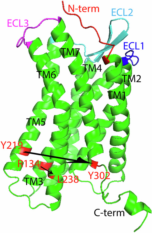
The residue R1343.50 is on TM3 and L2386.34 on TM6, Y2195.58 on TM5 and Y3027.53 on TM7. The distance from R1343.50 to L2386.34 (H3–H6 distance), and from Y2195.58 to Y3027.53 are calculated in DRY motif. The N-terminus (in red), extracellular loop region (ECL) 1 to 3 (in blue, cyan and magenta), TM helix 1–7, and C-terminus are labeled.
Fig. 6. DRY motif result for 11 simulations.

DRY motif result for full-length CXCL12 bound with full-length CXCR4, CXCR4 without residues from 1 to 26, and CXCR4 without residues from 1 to 26 or from 320 to 352 (a), and hBD-3 wildtype and linear analog bound with CXCR4 jobs, and 1 CXCR4 in free state at 313 K (b). The distance between R1343.50 and L2386.34 is shown in black solid line, and between Y2195.58 and Y3027.53 in brown dotted line. The reference lines at y = 8.4 Å and 14.1 Å for inactive and active state levels based on H3–H6 distance are shown in blue and green dashed lines.
Fig. 7. DRY motif result for 15 simulations.

The DRY motif result for 6 hBD-3 analogs bound with CXCR4 with the sequence of RES 27-319 initiated from HADDOCK docking and 1 mutant bound with CXCR4 with the sequence of RES 27-319 job (a), and for 6 hBD-3 analogs bound CXCR4 (sequence of RES 27-319) simulations and 2 CXCR4 (sequence of RES 27-319) in free state at two different temperatures (b). The distance between R1343.50 and L2386.34 is shown in black solid line, and between Y2195.58 and Y3027.53 in brown dotted line. The reference lines at y = 8.4 Å and 14.1 Å for inactive and active state levels based on H3–H6 distance are shown in blue and green dashed lines.
Based on the H3–H6 distance (R134-L238 distance) results shown in Fig. 6 (in black), CXCL12 bound with CXCR4 (CXCL12-f job) almost reaches an active state in the last 200 ns of the simulation, since the H3–H6 distance is close to 14.1 Å during this period; CXCL12 bound with CXCR4 (sequence of RES 27-319) (CXCL12-nht job) is in an active state from 1500 ns to 2400 ns of the simulation. Also, the R134-L238 distance shows an increasing tendency and the Y219-Y302 distance shows a decreasing tendency over the simulation time (in Fig. 6 (Left)) in both CXCL12-f and CXCL12-nht jobs, that corresponds to the TM6 outward tilting of CXCR4 in the activation process. Thus, the CXCR4 activation process was detected in those two jobs during the simulations, and both jobs are active or partially active. Although CXCR4 (with sequence of RES 27-319) in the free state at 313 K (free-CXCR4 job) is in an active state from 500 ns to 2400 ns, at 300 K (CXCR4-300K job) it was in an inactive state during 2.4 μs simulations; at 323 K (CXCR4-323K job) CXCR4 occasionally reaches an active state (at 1800 ns, 2300 ns) as shown in Fig. 7. Although CXCR4 bound with hBD-3 wt, linear analog, and most other analogs are in an inactive or intermediate state, CXCR4 bound with hBD-3 analog#2 from both HADDOCK docking and random-seed initiated simulations (analog#2-hd, analog#2-rs jobs) reach an active state sometimes, especially with hBD-3 analog#2-rs which was consistently in an active state from 1600 ns to 1800 ns in the simulation. CXCR4 bound with analog#3-rs and analog#6-rs also reach an active state sometimes. CXCR4 in HADDOCK docking initiated simulations have fewer active states than in random-seed initiated simulations. Besides that, checking the tendency of H3–H6 distance and Y219-Y302 distance during the simulation time, free-CXCR4, analog#2-rs, analog#6-rs, and CXCR4-323K jobs showed the activation tendency of CXCR4 during long-term simulations. Interestingly, CXCR4 in 8U4O job, which is in an active state, has its R134-L238 distance (around 14.1 Å) longer than Y219-Y302 distance (around 10 Å) consistently during 150 ns simulations. The reason should be that CXCR4 in 8U4O job started from an active state, which is different from other jobs which started from an inactive state of CXCR4. Although hbd3-wt-rs1 job also has a Y219-Y302 distance at around 10 Å, the R134-L238 distance is far from 14.1 Å and CXCR4 is in an inactive state as predicted.
Discussion
CXCL12 and hBD-3 compete for binding with CXCR4
In this project, the binding structures of CXCL12 and hBD-3 with chemokine receptor CXCR4 were predicted as the distance map shown in Fig. 4c. It was found that the binding sites of both kinds of ligands on CXCR4 are on the N-terminus, ECL2 and ECL3 regions. Therefore, the binding sites of hBD-3 can overlap with those of CXCL12 on CXCR4. Besides that, CXCL12 and hBD-3 have a comparable binding interaction energy with CXCR4 as shown in Supplementary Table S6. Those can support the experimental findings from Feng et al.14 that hBD-3 can compete with CXCL12 for binding with CXCR4, thus interrupting CXCL12-mediated signal pathways.
Based on the unbound experimental structures of CXCR4, hBD-3, and CXCL12, we performed HADDOCK docking and random-seed docking calculations and predicted the initial binding structures of hBD-3/t-CXCL12 with CXCR4. Afterwards, we embedded the complexes predicted in the phospholipid bilayers and carried out long-term Anton simulations to predict the most probable binding structures of CXCR4 with t-CXCL12 and hBD-3 in wildtype, analog forms, and mutant. Based on the RMSD values calculated for the heavy atoms, it was found that the seven helices region of CXCR4 in the bound state (with different ligands) has very small structural deviation (in the range of 2.8 Å to 4.0 Å) compared to the free state (4.0 to 4.3 Å at the same temperature), which corresponds to the crystal structure of the inactive form of CXCR4 (Table 1). For the activated form of CXCR4, the RMSD of the seven helices region differs from the crystal structure by only 3.3 Å for the CXCL12-f (CXCR4 bound with full-length CXCL12 starting from Tamamis et al.’s prediction) simulation, and for the inactivated form of CXCR4, an RMSD of 3.7 Å for hbd3-la-hd (CXCR4 bound with hBD-3 linear analog starting from HADDOCK) simulation was reached. During the long-term simulations, activation of full-length CXCR4 bound with CXCL12, and truncated CXCR4 bound with CXCL12 and hBD-3 analog#2-rs and analog#2-hd was observed. However, the RMSD of CXCR4 in those jobs is not really larger than that of CXCR4 in the inactive form.
Bound structures of CXCL12-CXCR4
Ziarek et al.55 analyzed the binding of CXCL12 monomer with the N-terminus of CXCR4 (residues M1NT-K381.42) experimentally. They found that CXCL12 should first bind to the N-terminus of CXCR4. The N-terminal domain of CXCR4 functions as a critical ligand binding site (CRS1), preceding the binding of the ligand on CXCR4 at the CRS2 site. However, in this project, HADDOCK docking and random-seed methods were applied to predict the most probable binding structure of t-CXCL12 (first 4 residues chopped) on CXCR4 (residues M1NT-E26NT chopped), thus only CRS2 and CRS1.5 binding sites were predicted. Refining the initial binding structures with long-term Anton simulations, the binding interface remained consistent overall. Based on the activity prediction using the H3–H6 distance, it was found that t-CXCL12 did not activate CXCR4 in both HADDOCK docking and random-seed method initiated simulations. The t-CXCL12 is missing the first 4 residues (KPVS). According to Crump et al.27, the first 2 residues are critical for receptor activation but not binding, and the 3rd and 4th residues do not have a dramatic effect on receptor activation like the first two residues. Our prediction aligns with Crump et al. However, CXCL12 can activate full-length CXCR4 (CXCR4-f) and CXCR4 with the sequence of RES 27-319 (CXCR4-nht). This highlights the importance and complexity of ligand binding sites on CXCR4 and their influence on receptor activity, as well as the possible allosteric regulation of CXCR4 signaling.
In addition to RMSD, RMSF, and hydrogen bond analysis, the binding free energy and the distance map between t-CXCL12 and hBD-3 in complex with CXCR4 were calculated (Supplementary Fig. S9 and Fig. 4a). Compared to the random-seed method initiated simulation (CXCL12-rs1 job), the binding structure from the CXCL12-hd simulation showed more conserved binding interfaces and overall was very close to the predictions from Tamamis et al.21 and the 8U4O structure22.
In this study, one simulation was conducted on the fully active state of CXCR4 bound with CXCL12 (starting from the 8U4O structure). The results predicted a much lower RMSD and RMSF of CXCL12 and CXCR4, a higher number of hydrogen bonds formed, and a much lower binding free energy between the receptor and ligand compared to other simulations. The deeper insertion of the N-terminus of CXCL12 into CXCR4 which results in a stronger binding affinity between the receptor and ligand should contribute to that. The DRY motif analysis showed that the R134-L238 is around 14.1 Å and Y219-Y302 distance is around 10 Å, which is different from all other simulations. This difference is attributed to the fact that 8U4O started from a fully active state, while other simulations initiated with CXCR4 in inactive state.
Bound structure of hBD-3-CXCR4
With the assumption that ligand should bind to the orthosteric binding pocket of CXCR4 to form a stable binding, the binding structures of CXCR4-ligands were suggested combining the distance map result (Fig. 4), the most probable structures exported (Fig. 3), and the binding interaction energy results shown in Supplementary Fig. S9. We ran a total of 13 different hBD-3 analogs/mutant binding with CXCR4 simulations. Only simulations having the CRS2 site could predict the stable binding sites. The interaction energy vs. time results for different simulations (shown in Supplementary Fig. S9) and the average and standard deviation of the interaction energies (shown in Supplementary Table S6) pointed out that usually binding structures on the CRS2 site correspond to a lower binding interaction energy. The simulations predicted stable binding structures are highlighted in red in the energy result column in Supplementary Table S6. In total, we did 3 hBD-3 wildtype binding on CXCR4 simulations, including hbd3-wt-rs1, hbd3-wt-rs2, hbd3-wt-hd simulations. Only hbd3-wt-rs2 has the N-terminus approaching the orthosteric pocket of CXCR4, and hbd3-wt-hd only had the first loop region reaching the outside of the orthosteric pocket of CXCR4. Thus, the complex structure predicted from hbd3-wt-rs2 seems to be more reasonable. That also agrees with the lower binding interaction energy results for the hbd3-wt-rs2 simulation as shown in Supplementary Fig. S9 and Supplementary Table S6. The hbd3-la-hd (CXCR4 bound with hBD-3 linear analog starting from HADDOCK) simulation has the lowest interaction energy thus the most stable binding among all the analogs. Experimental work such as using cryoEM method is needed to verify the stable binding structure of hBD-3 wildtype and analogs with CXCR4 in the future.
One hBD-3 mutant simulation was conducted, in which 3 important binding sites on hBD-3 were mutated into Ser residue (K8S, K32S, R36S). The binding sites of the hBD-3 mutant and CXCR4 are still on the CRS2 site, but less close contact between CXCR4 and hBD-3 was found, as shown in the distance map result in Fig. 4b, c. This agrees with Feng et al.’s result20. Additionally, such kind of mutation did not activate CXCR4 during the long-term simulations.
Furthermore, while hBD-3 wt binds to CXCR4 resulting in the inactive state, so does hBD3-la, as shown in Figs. 6 and 7. Analog#2-rs, analog#2-hd, analog#3-rs (temporarily), and analog#6-rs (temporarily) activated CXCR4 during the microsecond-long simulations. Comparing the disulfide bonding pattern for different analogs as shown in Supplementary Table S3, analog#2, analog#3, and analog#6 all have the Cys11-Cys40 disulfide bond present, with the other one or two disulfide bonds broken. Thus, our prediction suggests that the Cys11-Cys40 disulfide bond in hBD-3 analog form may switch hBD-3 from an antagonist to an agonist. Our results suggest that specific redox conditions can modulate the conformation of the ligand and thus the activity of CXCR4. In the future, more long-term simulations and enhanced simulation methods such as REST256 should be conducted to predict the bound structure of CXCR4 and ligands, and provide more molecular details on its activation process.
In this project, the binding of CXCR4 in monomer form with hBD-3 in different forms was studied. It has been found that CXCR4 can exist as a mixture of monomers, dimers, and higher-order oligomers in cell membranes57. The dimerization of CXCR4 can affect its activity58, and it can be affected by cholesterol in the membrane59, disrupted by antagonist IT1T57, and suppressed by inverse agonist binding to the TM1-3 and TM7 of CXCR460. Since hBD-3 wt and most analogs are antagonists for CXCR4 (as shown in Figs. 6 and 7), and can bind with CXCR4 on the TM1-3 and TM7 region as the binding interface shown in Fig. 4, it is expected that CXCR4 should stay in the monomer form when binding with those ligands. This justifies the method of studying hBD-3 in different forms binding with CXCR4 in monomer form in this work.
Conclusion
In our research, we have applied MD simulations to predict the binding structure and understand the interaction and dynamics of CXCR4 bound with different ligands. One is CXCL12, which should be an agonist, while t-CXCL12 is an antagonist. The other is hBD-3, which should be an antagonist in the wildtype and possibly an agonist in different redox conditions or in mutated form. The aim of the study was to predict the binding and interaction of hBD-3 and CXCL12 in different forms with CXCR4 using a combined simulation strategy, and to gain a better understanding of the role of ligand binding in the activity of CXCR4. It was found that different ligands can bind with CXCR4 stably, and some hBD-3 analogs and CXCL12 can activate CXCR4 based on the DRY motif calculation, while not t-CXCL12 which has the first 4 residues missing. We have shown that the binding structure of ligands with CXCR4 initiated by HADDOCK docking method always leads to the CRS2 binding sites on CXCR4, where the N-terminus of t-CXCL12, and the head or C2-C3 region of hBD-3 reaches the orthosteric pocket of CXCR4. hBD-3 analog#2, analog#3, and analog#6 can activate CXCR4 but not hBD-3 wildtype, linear analog or other analogs. The distance map result in this study explains why hBD-3 can block the binding of CXCL12 with CXCR4. The research findings provide insight into understanding the antagonist binding and interaction with the CXCR4 receptor.
Methods
Sequence and structures of proteins
For CXCR4 wt simulations, the crystal structure resolved by Wu et al.4 (PDB ID 3ODU), with RES1253.41 mutated back from Trp to Leu, was used (this is labeled in red in the sequence of Supplementary Table S1a). In order to build the full-length CXCR4 simulation, the first 26 residues (M1NT to E26NT) and the last 33 residues (V320CT to S352CT) were implemented using the modeller program61. The sequence and secondary structures of hBD-3 (PDB ID 1KJ6), CXCL12 (PDB ID 3GV3), and full-length CXCL12 with the first 4 residues and the last 1 residue implemented using the modeller program61 are shown in Supplementary Table S1b, c. The sequences of CXCR4 and CXCL12 used in simulations are listed in Supplementary Table S2. The reason for choosing the CXCR4 without the first 26 residues to bind with hBD-3 and t-CXCL12 is that there is experimental data available for this CXCR4 structure bound with different antagonists, such as IT1t, CVX15, and vMIP-II4, and t-CXCL12 is potentially an antagonist to CXCR413. We also worked on the full-length CXCR4, with only the first 26 residues chopped off, and with both the first 26 residues and the last 33 residues removed, bound with full-length CXCL12, in order to investigate how each part of CXCR4 can impact its activation by CXCL12. Since hBD-3 wt acts as an antagonist to CXCR4, we began the simulations using this inactive structure of CXCR4 in complex with hBD-3. In addition, based on the cryoEM structure of CXCR4 bound with CXCL12 in the active state (PDB ID 8U4O)22, one job was also set up with the sequence of CXCL12 from RES 1 to 65 and the sequence of CXCR4 from RES 24 to 318, as detailed in Supplementary Table S1 and listed in Supplementary Table S2. Because CXCR4 in 8U4O job is in active state and it functions as the reference active state, only 150 all-atom NAMD simulation was conducted on this job.
Simulation setup
Three CXCL12 bound with CXCR4 simulations, including full-length CXCL12 bound with full-length CXCR4, CXCR4 with the first 26 residues chopped, and CXCR4 with both the first 26 residues and the last 33 residues chopped simulations were set up based on the Tamamis predicted structures21. To set up the simulations of hBD-3 and t-CXCL12 bound with CXCR4 without the first 26 residues and the last 33 residues, the initial structures were predicted using both HADDOCK docking and random-seed methods as the strategies shown below.
The CXCR4 monomer without a ligand was inserted into a zwitterionic POPC lipid bilayer (which represents the normal red-blood cell membrane) using a in-house program, which finished the insertion process consistent with CHARMM-gui program62 based on our test. After solvation and neutralization using 0.15 M NaCl with detailed settings shown in “Simulation settings” subsection, all-atom molecular dynamics simulations were performed using NAMD program63 for 300 ns to predict the structure of CXCR4 monomer in the POPC lipid bilayer. After that, two methods were applied to predict the initial binding structures of the ligand with CXCR4. The first method involved placing the ligand (hBD-3/t-CXCL12 monomer) above the receptor, ensuring a minimum distance of 35 Å between the center of hBD-3/t-CXCL12 and the lipid bilayer surface to avoid bias from the initial hBD-3/t-CXCL12 structure and allowing the ligand to approach CXCR4 freely. Since electrostatic interaction is important for hBD-3 binding with receptors and lipids28, and hBD-3 has been found to bind with receptors and lipids on the β2 sheet region31,32, all initial structures were oriented so that the β2 sheet of hBD-3 faced the receptor and the lipid bilayer. The t-CXCL12 was aligned so that the head and β sheet region faced CXCR4 and the lipid membrane, as suggested by Tamamis and Floudas21. Additionally, the hBD-3/t-CXCL12 monomer binding with CXCR4 simulation was repeated 6 times, each starting from the same initial structure but with a different random seed. Different random seeds explicitly set up in the NAMD simulation, can initiate different velocity distributions of the atoms in each rerun simulation, ensuring different initial movements of the ligand towards the receptor. The simulation setup flowchart is shown in Fig. 8.
Fig. 8. The flowchart of the simulation setup and analysis processes.

The common parts are shown in orange boxes, the steps using the random-seed method (Method#1) are shown in green boxes, the steps using the HADDOCK docking method (Method#2) to generate initial structures are shown in blue boxes, while from Tamamis prediction is shown in purple. 8U4O job was set up using CHARMM-gui program with settings and analysis consistent with other jobs, but the NAMD simulation was only conducted for 150 ns.
Simulation settings
To predict the initial binding structure using the random-seed method, the ligand was placed 35 Å above the extracellular region of CXCR4 embedded inside a POPC bilayer. A sufficient amount of TIP3P explicit water molecules were added to achieve a water thickness above and below the protein of at least 15 Å. Counter-ions were added to neutralize each system, and Na+ and Cl- ions were further added to bring the NaCl concentration to 0.15 M. The CHARMM36m64 forcefield was applied. After a brief energy minimization using the conjugate gradient and line search algorithm, 4 ps of dynamics were run at 50 K, and then the system was heated to 310 K over a 1 ns equilibration period using the NAMD program version 2.1263, then unrestrained all-atom molecular dynamics simulations were performed at a temperature of 313 K to ensure that the POPC lipid bilayer remains in the fluid phase and at a desired pressure of 1 atm, using the NAMD program. The time step was 2 fs. The standard particle mesh Ewald method was used, along with periodic boundary conditions, to calculate the long-range electrostatic interactions of the system. For non-bonded calculations, a cutoff of 12 Å was used. All bonds involving hydrogen were kept rigid using the SHAKE algorithm. For each system, up to 300 ns of NAMD simulations were performed after equilibrating the systems. For both hBD-3 and t-CXCL12, a total of seven runs for each kind of ligand were performed for up to 300 ns using the NAMD program with the random-seed method. Only the bound structures from stable simulations (no dissociation or shifting on the binding interface) were selected as the stable initial structures from the random-seed method. In total, two hBD-3-CXCR4 simulations predicted stable complex structures from the random-seed method (named hbd3-wt-rs1 and hbd3-wt-rs2), while one CXCL12-CXCR4 simulation (named CXCL12-rs1) was selected.
In addition to using the random-seed method to predict the initial binding structure of the ligand on CXCR4, the HADDOCK docking program25,26 was also employed to predict stable initial binding structures for hBD-3/t-CXCL12 in complex with CXCR4 (named hbd3-wt-hd and CXCL12-hd simulations). Since we knew that the binding sites on CXCR4 are located on its N-terminal and extracellular regions, we performed targeted docking. The entire N-terminal and extracellular loop regions of CXCR4 were selected as the target binding sites. Default values were applied for all other parameters. Since having the ligand reach the orthosteric pocket of CXCR4 is necessary for its function27, and there are experimental studies on CXCL12 bound with CXCR413 and hBD-3 bound with CXCR414, we selected the best HADDOCK docking complexes from the top scored list that satisfied the binding interface information available13,14,21.
Furthermore, a total of seven hBD-3 monomers in different analog forms, corresponding to the number of disulfide bonds from 0 (the most reduced form) to 2 as shown in Supplementary Table S3 and one hBD-3 mutant, were docked using HADDOCK. The hBD-3 mutant was prepared using the VMD program from the hBD-3 wildtype structure (PDB ID 1KJ612). In this mutant, K8, K32, and R36 were mutated into Ser residues (K8S, K32S, R36S) since Feng et al. found that these residues are important for the binding of hBD-3 with CXCR414. The initial structures of hBD-3 analogs were prepared by removing some disulfide bonds from the wildtype structure (PDB ID: 1KJ6) using the CHARMM program65. The CHARMM program was applied to set up the initial systems for the ligands t-CXCL12 and hBD-3 (analogs, and mutant) in TIP3P water and 0.15 M NaCl to neutralize each system. Then, 500 ns all-atom unrestrained NAMD simulations were performed on each system at a temperature of 300 K and a desired pressure of 1 atm using the CHARMM36m forcefield. After that, the last frames of hBD-3 analogs and mutant from those solvent MD simulations were output, and used in the HADDOCK docking to CXCR4. The simulations performed based on HADDOCK docking initiated structures are shown in Supplementary Table S2.
Based on the best initial binding structures predicted from MD simulations for hBD-3 wildtype, analogs, and mutant, and t-CXCL12 bound with the CXCR4 receptor using both the random-seed method and the HADDOCK program, the CHARMM-GUI program62 was applied to set up the ligand-CXCR4 complexes embedded inside a POPC lipid bilayer. The water thickness above and below the protein was 30 Å. The simulation temperature was 313 K, and the pressure was 1 atm. The other settings in the NAMD simulations were the same as above for solvent simulation setup. At least 300 ns all-atom NAMD simulations were performed on local high performance computers before long-term simulations were continued on Anton266 with CHARMM36m forcefields, each for a total simulation length of 2.4 µs. For the hbd3-wt-rs2 simulation, although the initial binding structure was consistent during 300 ns of NAMD simulation, hBD-3 dissociated from CXCR4 very soon during the Anton simulations, then returned back and bound with CXCR4 stably with a slightly shifted binding site, as shown in Supplementary Video S1. Thus, a total of 4.8 µs was performed for this simulation. In order to consider the temperature effect on the activity of CXCR4, free CXCR4 in POPC bilayer simulations at both 300 K and 323 K were also performed since it was found that GPCR can be activated by thermal excitation of the environment and switch from the apo-state to the active state67.
In total, two hBD-3-CXCR4 simulations predicted conserved complex structures from the random-seed method (named hbd3-wt-rs1, hbd3-wt-rs2), while one t-CXCL12-CXCR4 simulation (named CXCL12-rs1) was selected, besides the simulation on CXCR4 in a free state, as shown in Supplementary Table S2. Since the disulfide bonding status of hBD-3 can affect its chemotactic activity14, we also set up the initial structures of hBD-3 analogs bound with CXCR4. Because the hbd3-wt-rs1 job shows a conserved complex structure during 2.4 μs, its initial structure from the random-seed method was used as the initial structure for different hBD-3 analogs by modifying the disulfide bonding status according to that shown in Supplementary Table S3.
In total, 27 long-term simulations were performed (with the simulation details shown in Supplementary Table S2). These include 3 hBD-3 wildtype monomer-CXCR4 complexes in POPC bilayer (2 from the random-seed method and 1 from HADDOCK docking), 1 hBD-3 linear analog (0 disulfide bond)-CXCR4 complex in POPC bilayer (from HADDOCK docking), 2 t-CXCL12-CXCR4 complexes in POPC bilayer (1 from the random-seed method and 1 from HADDOCK docking), 3 full-length CXCL12 bound with CXCR4 in different lengths, 3 free CXCR4 in POPC bilayer (different temperatures), 6 hBD-3 analogs (1 from the random-seed method and 1 from HADDOCK docking) and 1 hBD-3 mutant (from HADDOCK docking) bound with CXCR4 in POPC bilayer. Simulations were conducted for 2.4 μs each except the hBD-3 wt bound with CXCR4 from the random-seed method which was run for 4.8 μs. Besides that, in order to compare the structures of ligands bound with CXCR4 with those in the free state (in solvent only), hBD-3 wt/t-CXCL12 monomer in solvent water simulations were also performed for 0.5 μs each using the CHARMM program65. The flowchart of simulation setup using both HADDOCK docking and the random-seed method is shown in Fig. 8.
Trajectory analysis
Based on the microsecond-long simulation trajectories, the structure and dynamics of free CXCR4 and CXCR4 bound with different ligands embedded in POPC lipid bilayer were analyzed. The RMSD of CXCR4, ligands were calculated using the VMD program68 after aligning the trajectories to the corresponding reference structures of CXCR4 and ligands respectively. The reference structure of CXCR4 is the crystal structure of CXCR4 from PDB ID 3ODU, while the reference structure for hBD-3 wildtype is the crystal structure of the hBD-3 monomer. The reference structure of 8U4O job is the cryoEM detected structure of CXCL12 bound with CXCR4. The reference structures of hBD-3 analogs are the final structures of hBD-3 analogs in solvent after 500 ns simulations. Those reference hBD-3 analog structures were used to do docking with CXCR4 as shown in “Simulation setup” section. The reference structure for t-CXCL12 is the available crystal structure. Since the head and tail parts of CXCR4 are very flexible, they are not included in the CXCR4 RMSD calculation in both free and bound states. Root Mean Squared Fluctuation (RMSF) measures the deviation between atomic positions of residues and their averaged structure from the trajectory. The backbone Ca atom was selected to quantitatively measure the magnitude of deviation for each residue, and the whole simulation trajectories were applied in the RMSF calculation using VMD program and a Tcl code.
CHARMM program65 was applied to calculate the minimum distances between residue pairs important for CXCR4 activity. The number of hydrogen bonds formed between CXCR4 and CXCL12/hBD-3 was calculated using the VMD program68 with a distance cutoff of 3.0 Å and an angle cutoff of 20 degrees deviation from H-bond linearity. The time a particular H-bond formed over the course of the simulation is monitored and expressed as % occupancy. At least 10,000 frames from each trajectory (frequency is no more than 0.24 ns) were used in the protein-protein hydrogen bond calculation.
Based on the microsecond-long trajectories, structures of ligands bound with CXCR4 complexes were output with a frequency of 2.4 ns. After that, the wordom program69,70 was applied to cluster the structures with an RMSD cutoff of 5 Å, and the most probable structure was predicted.
To find out the residues on the binding interface, the closest distance between each residue atom pair (including hydrogen) from CXCR4 and from hBD-3/CXCL12 was calculated using CHARMM program and averaged over the sampling run. The average distances between each residue on CXCR4 and on ligand were shaded by proximity on a red to white color-scale and used to build the distance maps.
Furthermore, based on the long-term simulation trajectories of the complexes shown in Supplementary Table S2, the total pairwise interaction energy was calculated using the MM-GBSA method71 by applying NAMD and the NAMD energy plugin of the VMD program68. This interaction energy (Ebinding) is calculated using Eq. (1):
| 1 |
Ecomplex is the potential energy of the receptor-ligand complex, Ereceptor is the potential energy of the receptor, and Eligand is the potential energy of the ligand. < > denotes the ensemble average over simulation time. In the MM-GBSA method, the solvent effect was counted using the generalized Born implicit solvent model (GBIS)72.
Supplementary information
Description of Additional Supplementary Files
Acknowledgements
This work was supported by the Center of Energy Systems Research located in Tennessee Tech university to graduate student Jackson Penfield. Simulations were conducted using supercomputer time from Bridges machines from the Extreme Science and Engineering Discovery Environment (XSEDE) via an award to L.Z. (MCB160041). Anton 2 computer time was provided by the Pittsburgh Supercomputing Center (PSC) through Grant R01GM116961 from the National Institutes of Health. The Anton 2 machine at PSC was generously made available by D. E. Shaw Research. Some of the short-term simulations and analysis were carried out at the High Performance Computers (HPC) in Tennessee Technological University and in University of Rhode Island.
Author contributions
L.Z. conceived and designed the simulations. J.P. performed the docking and computational simulations, and conducted most of the analysis. L.Z. wrote the paper and did some analysis. Both authors read and approved the final paper.
Peer review
Peer review information
Communications Chemistry thanks Hao-Jen Hsu and the other, anonymous, reviewer(s) for their contribution to the peer review of this work.
Data availability
The authors declare that the data supporting the findings of this study are available within the paper and its Supplementary Information files.
Competing interests
The authors declare no competing interests.
Footnotes
Publisher’s note Springer Nature remains neutral with regard to jurisdictional claims in published maps and institutional affiliations.
Supplementary information
The online version contains supplementary material available at 10.1038/s42004-024-01280-6.
References
- 1.Baggiolini, M. Chemokines and leukocyte traffic. Nature392, 565–568 (1998). 10.1038/33340 [DOI] [PubMed] [Google Scholar]
- 2.Moser, B., Wolf, M., Walz, A. & Loetscher, P. Chemokines: multiple levels of leukocyte migration control. Trends Immunol.25, 75–84 (2004). 10.1016/j.it.2003.12.005 [DOI] [PubMed] [Google Scholar]
- 3.Mackay, C. R. Chemokines: immunology’s high impact factors. Nat. Immunol.2, 95–101 (2001). 10.1038/84298 [DOI] [PubMed] [Google Scholar]
- 4.Wu, B. et al. Structures of the CXCR4 chemokine GPCR with small-molecule and cyclic peptide antagonists. Science330, 1066–1071 (2010). 10.1126/science.1194396 [DOI] [PMC free article] [PubMed] [Google Scholar]
- 5.Koelink, P. J. et al. Targeting chemokine receptors in chronic inflammatory diseases: an extensive review. Pharmacol. Ther.133, 1–18 (2012). 10.1016/j.pharmthera.2011.06.008 [DOI] [PubMed] [Google Scholar]
- 6.Balkwill, F. The significance of cancer cell expression of the chemokine receptor CXCR4. Semin. Cancer Biol.14, 171–179 (2004). 10.1016/j.semcancer.2003.10.003 [DOI] [PubMed] [Google Scholar]
- 7.Zhao, H. et al. CXCR4 over-expression and survival in cancer: a system review and meta-analysis. Oncotarget6, 5022 (2015). 10.18632/oncotarget.3217 [DOI] [PMC free article] [PubMed] [Google Scholar]
- 8.Feng, Y., Broder, C. C., Kennedy, P. E. & Berger, E. A. HIV-1 entry cofactor: functional cDNA cloning of a seven-transmembrane, G protein-coupled receptor. Science272, 872–877 (1996). 10.1126/science.272.5263.872 [DOI] [PubMed] [Google Scholar]
- 9.Chong, B. F. & Mohan, C. Targeting the CXCR4/CXCL12 axis in systemic lupus erythematosus. Expert Opin. Ther. Targets13, 1147–1153 (2009). 10.1517/14728220903196761 [DOI] [PubMed] [Google Scholar]
- 10.Zou, Y. R., Kottmann, A. H., Kuroda, M., Taniuchi, I. & Littman, D. R. Function of the chemokine receptor CXCR4 in haematopoiesis and in cerebellar development. Nature393, 595–599 (1998). 10.1038/31269 [DOI] [PubMed] [Google Scholar]
- 11.Murphy, J. W., Yuan, H., Kong, Y., Xiong, Y. & Lolis, E. J. Heterologous quaternary structure of CXCL12 and its relationship to the CC chemokine family. Proteins78, 1331 (2010). 10.1002/prot.22666 [DOI] [PMC free article] [PubMed] [Google Scholar]
- 12.Schibli, D. J. et al. The solution structures of the human β-defensins lead to a better understanding of the potent bactericidal activity of HBD3 against Staphylococcus aureus. J. Biol. Chem.277, 8279–8289 (2002). 10.1074/jbc.M108830200 [DOI] [PubMed] [Google Scholar]
- 13.Qin, L. et al. Crystal structure of the chemokine receptor CXCR4 in complex with a viral chemokine. Science347, 1117–1122 (2015). [DOI] [PMC free article] [PubMed]
- 14.Feng, Z., Dubyak, G. R., Jia, X., Lubkowski, J. T. & Weinberg, A. Human β‐defensin‐3 structure motifs that are important in CXCR 4 antagonism. FEBS J.280, 3365–3375 (2013). 10.1111/febs.12328 [DOI] [PMC free article] [PubMed] [Google Scholar]
- 15.Kaiser, V. & Diamond, G. Expression of mammalian defensin genes. J. Leukoc. Biol.68, 779–784 (2000). 10.1189/jlb.68.6.779 [DOI] [PubMed] [Google Scholar]
- 16.García, J. R. et al. Identification of a novel, multifunctional β-defensin (human β-defensin 3) with specific antimicrobial activity. Cell Tissue Res.306, 257–264 (2001). 10.1007/s004410100433 [DOI] [PubMed] [Google Scholar]
- 17.Wu, Z. et al. Engineering disulfide bridges to dissect antimicrobial and chemotactic activities of human β-defensin 3. Proc. Natl Acad. Sci.100, 8880–8885 (2003). 10.1073/pnas.1533186100 [DOI] [PMC free article] [PubMed] [Google Scholar]
- 18.Hoover, D. M., Wu, Z., Tucker, K., Lu, W. & Lubkowski, J. Antimicrobial characterization of human β-defensin 3 derivatives. Antimicrob. Agents Chemother.47, 2804–2809 (2003). 10.1128/AAC.47.9.2804-2809.2003 [DOI] [PMC free article] [PubMed] [Google Scholar]
- 19.Zhang, L. Different dynamics and pathway of disulfide bonds reduction of two human defensins, a molecular dynamics simulation study. Proteins85, 665–681 (2017). 10.1002/prot.25247 [DOI] [PubMed] [Google Scholar]
- 20.Feng, Z., Dubyak, G. R., Lederman, M. M. & Weinberg, A. Cutting edge: human β defensin 3—a novel antagonist of the HIV-1 coreceptor CXCR4. J. Immunol.177, 782–786 (2006). 10.4049/jimmunol.177.2.782 [DOI] [PubMed] [Google Scholar]
- 21.Tamamis, P. & Floudas, C. A. Elucidating a key component of cancer metastasis: CXCL12 (SDF-1α) binding to CXCR4. J. Chem. Inf. Model.54, 1174–1188 (2014). 10.1021/ci500069y [DOI] [PMC free article] [PubMed] [Google Scholar]
- 22.Saotome, K. et al. Structural insights into CXCR4 modulation and oligomerization. Biorxiv10.1101/2024.02.09.579708 (2024).
- 23.Babcock, G. J., Farzan, M. & Sodroski, J. Ligand-independent dimerization of CXCR4, a principal HIV-1 coreceptor. J. Biol. Chem.278, 3378–3385 (2003). 10.1074/jbc.M210140200 [DOI] [PubMed] [Google Scholar]
- 24.Percherancier, Y. et al. Bioluminescence resonance energy transfer reveals ligand-induced conformational changes in CXCR4 homo-and heterodimers. J. Biol. Chem.280, 9895–9903 (2005). 10.1074/jbc.M411151200 [DOI] [PubMed] [Google Scholar]
- 25.Vila‐Coro, A. J. et al. The chemokine SDF‐lα triggers CXCR4 receptor dimerization and activates the JAK/STAT pathway. FASEB J.13, 1699–1710 (1999). 10.1096/fasebj.13.13.1699 [DOI] [PubMed] [Google Scholar]
- 26.Levoye, A., Balabanian, K., Baleux, F., Bachelerie, F. & Lagane, B. CXCR7 heterodimerizes with CXCR4 and regulates CXCL12-mediated G protein signaling. Blood113, 6085–6093 (2009). 10.1182/blood-2008-12-196618 [DOI] [PubMed] [Google Scholar]
- 27.Crump, M. P. et al. Solution structure and basis for functional activity of stromal cell‐derived factor‐1; dissociation of CXCR4 activation from binding and inhibition of HIV‐1. EMBO J.16, 6996–7007 (1997). 10.1093/emboj/16.23.6996 [DOI] [PMC free article] [PubMed] [Google Scholar]
- 28.Dominguez, C., Boelens, R. & Bonvin, A. M. HADDOCK: a protein–protein docking approach based on biochemical or biophysical information. J. Am. Chem. Soc.125, 1731–1737 (2003). 10.1021/ja026939x [DOI] [PubMed] [Google Scholar]
- 29.Van Zundert, G. C. P. et al. The HADDOCK2. 2 web server: user-friendly integrative modeling of biomolecular complexes. J. Mol. Biol.428, 720–725 (2016). 10.1016/j.jmb.2015.09.014 [DOI] [PubMed] [Google Scholar]
- 30.Brewer, A. & Zhang, L. Binding free energy calculation of human beta defensin 3 with negatively charged lipid bilayer using free energy perturbation method. Biophys. Chem.277, 106662 (2021). 10.1016/j.bpc.2021.106662 [DOI] [PubMed] [Google Scholar]
- 31.Kang, X. et al. Integrated solid-state NMR and molecular dynamics modeling determines membrane insertion of human β-defensin analog. Commun. Biol.2, 1–10 (2019). 10.1038/s42003-019-0653-6 [DOI] [PMC free article] [PubMed] [Google Scholar]
- 32.Zhang, L. Disulfide bonds affect the binding sites of human β defensin type 3 on negatively charged lipid membranes. J. Phys. Chem. B.124, 2088–2100 (2020). 10.1021/acs.jpcb.9b10529 [DOI] [PubMed] [Google Scholar]
- 33.Wescott, M. P. et al. Signal transmission through the CXC chemokine receptor 4 (CXCR4) transmembrane helices. Proc. Natl Acad. Sci.113, 9928–9933 (2016). 10.1073/pnas.1601278113 [DOI] [PMC free article] [PubMed] [Google Scholar]
- 34.Scholten, D. J. et al. Pharmacological modulation of chemokine receptor function. Br. J. Pharmacol.165, 1617–1643 (2012). 10.1111/j.1476-5381.2011.01551.x [DOI] [PMC free article] [PubMed] [Google Scholar]
- 35.Gustavsson, M., Dyer, D. P., Zhao, C. & Handel, T. M. Kinetics of CXCL12 binding to atypical chemokine receptor 3 reveal a role for the receptor N terminus in chemokine binding. Sci. Signal.12, eaaw3657 (2019). 10.1126/scisignal.aaw3657 [DOI] [PMC free article] [PubMed] [Google Scholar]
- 36.Wingler, L. M. et al. Angiotensin analogs with divergent bias stabilize distinct receptor conformations. Cell176, 468–478 (2019). 10.1016/j.cell.2018.12.005 [DOI] [PMC free article] [PubMed] [Google Scholar]
- 37.Wingler, L. M. et al. Angiotensin and biased analogs induce structurally distinct active conformations within a GPCR. Science367, 888–892 (2020). 10.1126/science.aay9813 [DOI] [PMC free article] [PubMed] [Google Scholar]
- 38.Niesen, M. J., Bhattacharya, S. & Vaidehi, N. The role of conformational ensembles in ligand recognition in G-protein coupled receptors. J. Am. Chem. Soc.133, 13197–13204 (2011). 10.1021/ja205313h [DOI] [PubMed] [Google Scholar]
- 39.Hofmann, K. P. et al. A G protein-coupled receptor at work: the rhodopsin model. Trends Biochem. Sci.34, 540–552 (2009). 10.1016/j.tibs.2009.07.005 [DOI] [PubMed] [Google Scholar]
- 40.Nygaard, R., Frimurer, T. M., Holst, B., Rosenkilde, M. M. & Schwartz, T. W. Ligand binding and micro-switches in 7TM receptor structures. Trends Pharmacol. Sci.30, 249–259 (2009). 10.1016/j.tips.2009.02.006 [DOI] [PubMed] [Google Scholar]
- 41.Trzaskowski, B. et al. Action of molecular switches in GPCRs-theoretical and experimental studies. Curr. Med. Chem.19, 1090–1109 (2012). 10.2174/092986712799320556 [DOI] [PMC free article] [PubMed] [Google Scholar]
- 42.Schwartz, T. W., Frimurer, T. M., Holst, B., Rosenkilde, M. M. & Elling, C. E. Molecular mechanism of 7TM receptor activation—a global toggle switch model. Annu. Rev. Pharmacol. Toxicol.46, 481–519 (2006). 10.1146/annurev.pharmtox.46.120604.141218 [DOI] [PubMed] [Google Scholar]
- 43.Shi, L. et al. β2 adrenergic receptor activation: modulation of the proline kink in transmembrane 6 by a rotamer toggle switch. J. Biol. Chem.277, 40989–40996 (2002). 10.1074/jbc.M206801200 [DOI] [PubMed] [Google Scholar]
- 44.Rosenbaum, D. M., Rasmussen, S. G. & Kobilka, B. K. The structure and function of G-protein-coupled receptors. Nature459, 356–363 (2009). 10.1038/nature08144 [DOI] [PMC free article] [PubMed] [Google Scholar]
- 45.Mertz, B., Struts, A. V., Feller, S. E. & Brown, M. F. Molecular simulations and solid-state NMR investigate dynamical structure in rhodopsin activation. Biochim. Biophys. Acta1818, 241–251 (2012). 10.1016/j.bbamem.2011.08.003 [DOI] [PMC free article] [PubMed] [Google Scholar]
- 46.Palczewski, K. et al. Crystal structure of rhodopsin: a G protein-coupled receptor. Science289, 739–745 (2000). 10.1126/science.289.5480.739 [DOI] [PubMed] [Google Scholar]
- 47.Ballesteros, J. A. et al. Activation of the beta 2-adrenergic receptor involves disruption of an ionic lock between the cytoplasmic ends of transmembrane segments 3 and 6. J. Biol. Chem.276, 29171–29177 (2001). 10.1074/jbc.M103747200 [DOI] [PubMed] [Google Scholar]
- 48.Salon, J. A., Lodowski, D. T. & Palczewski, K. The significance of G protein-coupled receptor crystallography for drug discovery. Pharmacol. Rev.63, 901–937 (2011). 10.1124/pr.110.003350 [DOI] [PMC free article] [PubMed] [Google Scholar]
- 49.Rovati, G. E. et al. The DRY motif and the four corners of the cubic ternary complex model. Cell Signal.35, 16–23 (2017). 10.1016/j.cellsig.2017.03.020 [DOI] [PubMed] [Google Scholar]
- 50.Manglik, A. & Kruse, A. C. Structural basis for G protein-coupled receptor activation. Biochemistry56, 5628–5634 (2017). 10.1021/acs.biochem.7b00747 [DOI] [PMC free article] [PubMed] [Google Scholar]
- 51.Rasmussen, S. G. et al. Crystal structure of the β2 adrenergic receptor–Gs protein complex. Nature477, 549–555 (2011). 10.1038/nature10361 [DOI] [PMC free article] [PubMed] [Google Scholar]
- 52.Mollaei, P. & Farimani, A. B. Activity map and transition pathways of G protein-coupled receptor revealed by machine learning. J. Chem. Inf. Model.63, 2296–2304 (2023). 10.1021/acs.jcim.3c00032 [DOI] [PMC free article] [PubMed] [Google Scholar]
- 53.Cherezov, V. et al. High-resolution crystal structure of an engineered human β2-adrenergic G protein-coupled receptor. Science318, 1258–1265 (2007). 10.1126/science.1150577 [DOI] [PMC free article] [PubMed] [Google Scholar]
- 54.Chang, C. C. et al. Internal water channel formation in CXCR4 is crucial for Gi-protein coupling upon activation by CXCL12. Commun. Chem.3, 133 (2020). 10.1038/s42004-020-00383-0 [DOI] [PMC free article] [PubMed] [Google Scholar]
- 55.Ziarek, J. J. et al. Structural basis for chemokine recognition by a G protein-coupled receptor and implications for receptor activation. Sci. Signal.10, eaah5756 (2017). 10.1126/scisignal.aah5756 [DOI] [PMC free article] [PubMed] [Google Scholar]
- 56.Wang, L., Richard, A. F. & Berne, B. J. Replica exchange with solute scaling: a more efficient version of replica exchange with solute tempering (REST2). J. Phys. Chem. B115, 9431–9438 (2011). 10.1021/jp204407d [DOI] [PMC free article] [PubMed] [Google Scholar]
- 57.Ward, R. J. et al. Chemokine receptor CXCR4 oligomerization is disrupted selectively by the antagonist ligand IT1t. J. Biol. Chem.296, 100139 (2021). 10.1074/jbc.RA120.016612 [DOI] [PMC free article] [PubMed] [Google Scholar]
- 58.Di Marino, D., Conflitti, P., Motta, S. & Limongelli, V. Structural basis of dimerization of chemokine receptors CCR5 and CXCR4. Nat. Commun.14, 6439 (2023). 10.1038/s41467-023-42082-z [DOI] [PMC free article] [PubMed] [Google Scholar]
- 59.Pluhackova, K., Gahbauer, S., Kranz, F., Wassenaar, T. A. & Böckmann, R. A. Dynamic cholesterol-conditioned dimerization of the G protein coupled chemokine receptor type 4. PLoS Comput. Biol.12, e1005169 (2016). 10.1371/journal.pcbi.1005169 [DOI] [PMC free article] [PubMed] [Google Scholar]
- 60.Işbilir, A. et al. Advanced fluorescence microscopy reveals disruption of dynamic CXCR4 dimerization by subpocket-specific inverse agonists. Proc. Natl Acad. Sci. USA117, 29144–29154 (2020). 10.1073/pnas.2013319117 [DOI] [PMC free article] [PubMed] [Google Scholar]
- 61.Šali, A. & Blundell, T. L. Comparative protein modelling by satisfaction of spatial restraints. J. Mol. Biol.234, 779–815 (1993). 10.1006/jmbi.1993.1626 [DOI] [PubMed] [Google Scholar]
- 62.Jo, S., Lim, J. B., Klauda, J. B. & Im, W. CHARMM-GUI membrane builder for mixed bilayers and its application to yeast membranes. Biophys. J.97, 50–58 (2009). 10.1016/j.bpj.2009.04.013 [DOI] [PMC free article] [PubMed] [Google Scholar]
- 63.Phillips, J. C. et al. Scalable molecular dynamics with NAMD. J. Comput. Chem.26, 1781–1802 (2005). 10.1002/jcc.20289 [DOI] [PMC free article] [PubMed] [Google Scholar]
- 64.Huang, J. et al. CHARMM36m: an improved force field for folded and intrinsically disordered proteins. Nat. Methods14, 71–73 (2017). 10.1038/nmeth.4067 [DOI] [PMC free article] [PubMed] [Google Scholar]
- 65.Brooks, B. R. et al. CHARMM: the biomolecular simulation program. J. Comput. Chem.30, 1545–1614 (2009). 10.1002/jcc.21287 [DOI] [PMC free article] [PubMed] [Google Scholar]
- 66.Shaw, D. E. et al. Anton 2: raising the bar for performance and programmability in a special-purpose molecular dynamics supercomputer. SC'14: Proceedings of the International Conference for High Performance Computing, Networking, Storage and Analysis 41–53 (2014).
- 67.Tehan, B. G., Bortolato, A., Blaney, F. E., Weir, M. P. & Mason, J. S. Unifying family A GPCR theories of activation. Pharmacol. Ther.143, 51–60 (2014). 10.1016/j.pharmthera.2014.02.004 [DOI] [PubMed] [Google Scholar]
- 68.Humphrey, W., Dalke, A. & Schulten, K. VMD: visual molecular dynamics. J. Mol. Graph.14, 33–38 (1996). 10.1016/0263-7855(96)00018-5 [DOI] [PubMed] [Google Scholar]
- 69.Seeber, M., Cecchini, M., Rao, F., Settanni, G. & Caflisch, A. Wordom: a program for efficient analysis of molecular dynamics simulations. Bioinformatics23, 2625–2627 (2007). 10.1093/bioinformatics/btm378 [DOI] [PubMed] [Google Scholar]
- 70.Seeber, M. et al. Wordom: a user‐friendly program for the analysis of molecular structures, trajectories, and free energy surfaces. J. Comput. Chem.32, 1183–1194 (2011). 10.1002/jcc.21688 [DOI] [PMC free article] [PubMed] [Google Scholar]
- 71.Genheden, S. & Ryde, U. The MM/PBSA and MM/GBSA methods to estimate ligand-binding affinities. Expert. Opin. Drug Discov.10, 449–461 (2015). 10.1517/17460441.2015.1032936 [DOI] [PMC free article] [PubMed] [Google Scholar]
- 72.Tanner, D. E., Chan, K. Y., Phillips, J. C. & Schulten, K. Parallel generalized Born implicit solvent calculations with NAMD. J. Chem. Theory Comput.7, 3635–3642 (2011). 10.1021/ct200563j [DOI] [PMC free article] [PubMed] [Google Scholar]
Associated Data
This section collects any data citations, data availability statements, or supplementary materials included in this article.
Supplementary Materials
Description of Additional Supplementary Files
Data Availability Statement
The authors declare that the data supporting the findings of this study are available within the paper and its Supplementary Information files.