Abstract
People with transtibial limb loss frequently experience suboptimal gait outcomes. This is partly attributable to the absence of the biarticular gastrocnemius muscle, which plays a unique role in walking. Although a recent surge of biarticular prostheses aims to restore gastrocnemius function, the broad design space and lack of consensus on optimal hardware and control strategies present scientific and engineering challenges. This study introduces a robotic biarticular prosthesis emulator, comprising a uniarticular ankle-foot prosthesis and knee flexion exoskeleton, each actuated by a custom off-board system. Benchtop experiments were conducted to characterize the emulator’s mechatronic performance. Walking experiments with one transtibial amputee demonstrated the system’s capability to provide knee and ankle assistance. The −3 dB bandwidths for the knee exoskeleton’s torque and motor velocity controllers were measured at approximately 5 Hz and 100 Hz, respectively. A feedforward iterative learning controller reduced the root-mean-squared torque tracking error from 6.04 Nm to 0.99 Nm in hardware-in-the-loop experiments, an 84% improvement. User-preference-based tuning yielded a peak knee torque of approximately 20% of the estimated biological knee moment. This biarticular prosthesis emulator demonstrates significant potential as a versatile research platform that can offer valuable insights for the advancement of lower-limb assistive devices.
Keywords: Gastrocnemius, assistive devices, exoskeleton, amputation
Introduction
People with transtibial amputation (PwTA) face significant mobility challenges, including lower daily step counts, asymmetric walking patterns, and poor performance on clinical measures of functional mobility, when compared to the general population.1,2 Additionally, PwTA are susceptible to secondary musculoskeletal diseases, such as knee and hip osteoarthritis as well as chronic lower back pain.3–5 This susceptibility is likely a consequence of the cumulative, asymmetric limb loading experienced during walking and other activities of daily living. Although advances in ankle-foot prosthesis technology offer some promise for mitigating these issues, current state-of-the-art robotic ankle-foot prostheses have yet to substantially improve the functional mobility of PwTA. Even with these advanced prostheses, challenges like low daily step counts and asymmetric gait patterns persist.2,6
One potential reason for the limitations observed in powered ankle-foot prostheses may stem from the fact that modern designs do not accurately replicate the anatomical configuration of the human plantarflexor muscles. The primary ankle plantarflexors, known as the triceps surae, consist of two muscles: the soleus and the gastrocnemius. The soleus is a uniarticular muscle crossing only the ankle joint, whereas the gastrocnemius is biarticular, crossing both the ankle and knee joints. Current ankle-foot prostheses, whether powered or passive, are inherently limited to emulating behaviors akin to those provided by the soleus. As a consequence, these devices fail to replicate the coupled knee flexion moments that are characteristically provided by the gastrocnemius.
Simulation and experimental studies have established that the soleus and gastrocnemius muscles have distinct roles in locomotion. While both contribute to vertical bodyweight support and forward propulsion, the soleus primarily provides bodyweight support, and the gastrocnemius is more instrumental in propelling the center of mass forward.7–11 Induced acceleration analyses from simulations9,11 and experimental studies using external force application, electromyography, and muscle activation perturbations7,8,10 have confirmed these distinct roles. The gastrocnemius may also contribute to preventing knee hyperextension during mid-stance, though this role may be directly linked to forward propulsion.
The absence of a functional gastrocnemius muscle in PwTA significantly affects their gait mechanics. Simulation studies on walking with passive energy-storage-and-return prostheses have shown that these devices can mimic the soleus muscle’s role in providing vertical bodyweight support, but fail to replicate the gastrocnemius’ forward-propulsive action. 12 Gait analysis studies reveal lower knee flexion moments in the amputated limb during midstance, regardless of prosthesis type.2,13 Without the gastrocnemius, PwTA must rely on compensatory strategies involving other muscles in the amputated limb for forward propulsion, 14 which may contribute to long-term musculoskeletal issues. Consequently, developing a new class of assistive devices that can reproduce the biarticular function of the gastrocnemius could potentially enhance both the mobility and long-term musculoskeletal health of PwTA.
Recent research has begun to investigate the potential of assistive devices that integrate ankle prostheses with knee-assistance mechanisms, referred to here as biarticular prostheses (BPs). A range of designs has emerged, encompassing both passive and powered ankle prostheses as well as quasi-passive and powered knee exoskeletons or exosuits.15–20 While some preliminary studies report encouraging outcomes, such as enhanced metabolic walking economy and reduced hip compensations,16,17,21 these works are exploratory and preclinical.
There is uncertainty surrounding the optimal high-level design choices for BPs, such as whether joints should be powered or passive, and how these decisions affect user performance. Researchers have explored various configurations, each with its own set of advantages and limitations in terms of sensing, actuation, control, and user comfort. Existing devices have have made trade-offs in this space, including (1) relying on quasi-passive knee hardware,16,19 (2) not including the knee angle sensors required for many knee exoskeleton control strategies, 20 and (3) relying on commercial ankle-foot prosthesis hardware and control algorithms that do not acknowledge the additional biarticular knee componentry.16,17 Each of these trade-offs simplify electromechanical design problems, but are barriers to flexibly experimenting across candidate device designs. To advance the understanding and development of BPs, a research platform is needed that can efficiently investigate different design choices and their effects on user outcomes, while providing the flexibility to emulate a wide range of device architectures and control strategies.
This paper introduces a novel robotic biarticular prosthesis emulator, comprising a powered ankle prosthesis and a knee flexion exoskeleton, both driven by a custom off-board actuation and control system. Emulators serve as platforms to accelerate systematic research and development, spanning the domains of basic biomechanics, hardware design, and control system design. 22 To our knowledge, we present the only biarticular prosthesis emulator that includes (1) powered knee and ankle componentry, (2) joint encoders at both joints, and (3) modular robotic hardware and software explicitly designed for the purpose of emulating BPs. This work establishes the emulator as a research platform, setting the stage for future investigations into the development of untethered biarticular prostheses. We provide a comprehensive description of the hardware and control algorithms, supported by a series of benchtop tests such as step responses, torque control bandwidth experiments, and hardware-in-the-loop tests of walking. The overarching aim of this work is to offer a detailed account of the design of the biarticular prosthesis emulator, demonstrating its potential as a research platform for enhancing the mobility of people with transtibial limb loss.
Mechanical design
This section describes our design intent for the biarticular prosthesis emulator, as well as the design of the offboard actuation system the two assistive devices.
Design intent
The design space for biarticular prostheses is vast, encompassing a range of device types that could potentially improve walking patterns for PwTA. Therefore, it is essential to consider the biomechanical roles of the muscles we aim to emulate. For instance, during walking, the gastrocnemius primarily functions isometrically—actively maintaining a nearly constant muscle length while the Achilles tendon elongates and stores energy. 23 This observation suggests that a quasi-passive spring-clutch biarticular prosthesis could replicate much of the gastrocnemius’ functionality without the need for heavy batteries or actuators. Conversely, the gastrocnemius also provides between 3 and 5 J of net positive work during each stride,12,24 indicating that powered devices might be necessary for full functionality.
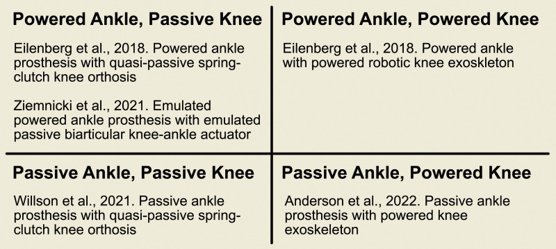
Given these biomechanical insights, our design intent was to create a prosthesis emulator capable of emulating a wide variety of potential device embodiments (Figure 1). This choice was informed by the overarching gaps in the field: the lack of a clear consensus on the optimal architecture and control mechanisms for such devices. Only a fully robotic system allows for the comprehensive exploration of passive, quasi-passive, and powered device options through robotic emulation.
Figure 1.
The potential design space for biarticular prostheses, partitioned by the devices’ ability to deliver net positive work at each joint over a stride. Examples of each device embodiment from the literature are shown for each combination. The robotic prosthesis introduced in this work was designed with the ability to emulate devices in all four quadrants.
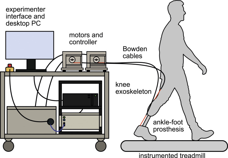
Our system comprises two independent assistive devices: a uniarticular ankle prosthesis and a uniarticular knee flexion exoskeleton (Figure 2). We opted for this configuration to allow for the emulation of biarticular prostheses with virtual lever arms that can be adjusted in software. Given that the function of biarticular muscles is highly sensitive to lever arm ratio, 25 this design choice avoids the issue of a fixed mechanical lever arm ratio and allows for future studies of uniarticular ankle prostheses using the same hardware.
Figure 2.
A schematic of the biarticular prosthesis emulator with primary components labeled. A research participant with transtibial limb loss walks on an instrumented treadmill while wearing the robotic ankle-foot prosthesis and exoskeleton. The stationary cart holds two servomotor actuators, a high-voltage servo circuit, a high-speed industrial controller, and a desktop computer that acts as an experimenter interface. Sensors from the prosthesis, exoskeleton, and treadmill are read by the industrial controller.
We developed a robotic BP emulator so that we can efficiently explore the design space on a single hardware platform. We can find out what devices are most helpful and what trade-offs they require. For example, we can directly compare emulated quasi-passive designs to emulated powered designs, find potential device designs that are helpful, and then build those devices for further experiments.
Setting design requirements for our emulator presented a significant challenge due to the complexity of the design space and the absence of established guidelines for biarticular prostheses. Our aim was to create a comprehensive system, and thus the design needed to be capable of emulating a range of device types, from passive to powered. Specifically, the ankle-foot component must be capable of both mimicking passive behaviors and delivering powered push-off. Likewise, the knee exoskeleton needs to render a spectrum of torque behaviors—passive, quasi-passive, and powered. In quasi-passive modes, for instance, real-time joint angle measurements and gait event detection are used to emulate spring-like torques during the stance phase of walking. For powered modes, a pre-defined torque signal may be commanded based on the detected gait phase, independent of joint kinematics. To support these functionalities, the system incorporates sensors for real-time joint angle measurements at each joint and employs algorithms for gait phase estimation. Moreover, modularity was prioritized in both hardware and software design to enable a broad range of future experiments and device modifications.
Off-board actuators and transmission design
The BP emulator uses a custom Configurable Off-Board Robotic Actuator (COBRA) and control platform to provide torques to the ankle-foot prosthesis and knee exoskeleton. The COBRA platform was introduced in prior work for a single-actuator configuration, 26 and we have added a second actuator and transmission to provide independent multi-joint torques to the BP.
Each wearable device is actuated by a 5.47 kW AKM74L servomotor (Kollmorgen, Radford, VA) and a custom Bowden cable transmission. The custom transmission includes Bowden cables and hardware to convert torque from the motor to Bowden cable force. The Bowden cable transmission consists of a synthetic rope and an outer flexible sheath made of coiled steel, with a PTFE liner to reduce friction. The forces in the rope and sheath are equal and opposite at each end, allowing for pure torques to be transmitted to the wearable devices without applying a net force to the user. 27 In terms of the custom hardware, the motors are attached to steel drive shafts supported by ball bearings, with a 2.51 cm radius sheave mounted to the output of each drive shaft to pull on the inner sheath of the Bowden cable. The outer sheath is rigidly clamped to the aluminum chassis of the transmission. The continuous and peak torques of the servomotors, as listed by the manufacturer, are 49.7 Nm and 143 Nm, respectively.
The servomotors are commutated by two AKD servo drives and a custom high-voltage circuit, which is powered by a three-phase 208 V wall outlet with a peak current of 30 A. The transmissions, drive circuit, and control computers are all placed on a stationary cart with wheels.
Ankle-foot prosthesis design
The BP emulator uses a robotic ankle-foot prosthesis end-effector previously developed by our research group, the COBRA Ankle. 26 The important features of the design are recounted here for completeness.
The COBRA Ankle is a Bowden cable driven prosthesis consisting of a custom pivot joint and an off-the-shelf carbon fiber footplate. The footplate can be sized to each participant and fits inside a wide range of shoe sizes. Plantarflexion moments are provided by the Bowden cable and dorsiflexion moments are provided by a pair of parallel torsion springs that are nested within the joint. Ankle joint angle and Bowden cable force are measured in real-time with a magnetic rotary encoder and load cell, respectively. Ankle torque is estimated in real-time using the encoder angle, load cell force, and models of the lever arm geometry and spring torque-angle relationship. The ankle has a peak torque of over 175 Nm, a range of motion of 46°, and a torque control bandwidth of 6.1 Hz.
Knee exoskeleton design
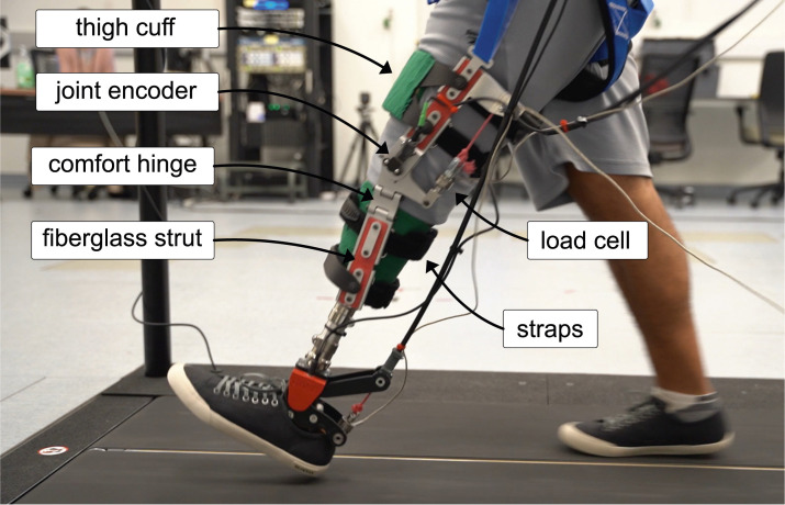
The knee exoskeleton described here is a second-generation design of the device described in a prior study. 15 The exoskeleton provides a knee flexion moment with a Bowden cable that enters the lateral posterior portion of the exoskeleton and is routed down the thigh with a pulley (Figure 3). The exoskeleton has rigid, planar fiberglass struts on the medial and lateral sides of the residual limb. The struts are connected with custom components machined from aluminum 7075 – including rotary joints that consists of steel shafts and ball bearings on each side of the knee. Though only the lateral side of the exoskeleton is actuated by the Bowden cable, early experiments with prototype devices indicated that exoskeleton migration was reduced and comfort was improved if a medial strut was included. Hard stops limit the exoskeleton range of motion between 5° of hyperextension and 90° of flexion. A component with two hinges was included below the knee joint to allow for leg tapering and frontal plane misalignment between the thigh, residual femur, and prosthetic socket, based on the design described in Wang et al. 28
Figure 3.
A photograph of a participant walking in the biarticular prosthesis. Key components of the exoskeleton hardware are labeled.
The exoskeleton’s sagittal plane joint angle is measured with a contactless magnetic encoder on the lateral joint (RM08, Renishaw). Bowden cable force is measured with an in-line tension load-cell (FSH03887, Futek) that is connected to a pivot at the end of a lever arm on the exoskeleton joint. The effective lever arm of the Bowden cable varies with the joint angle, so a polynomial model was created that maps the joint angle measurement to the lever arm length across the range of motion. Data from the exoskeleton CAD model was used to create the polynomial model (R2 of ). The joint torque applied by the exoskeleton is estimated in real-time by multiplying the Bowden cable force measurement with the lever arm estimate.
A rigid thigh cuff connects the two sides of the exoskeleton and delivers forces to the user’s thigh. The thigh cuffs are customized to each user’s leg dimensions by taking measurements of thigh circumference at two points above the knee joint. These dimensions are used to design a thigh cuff component that is laser cut from a flat sheet of thermoplastic. The thermoplastic sheet is then heat formed to either the participant’s leg or the leg of a mannequin. This workflow was initially proposed in Wang et al. 28 The thermoplastic cuff is lined with neoprene foam for comfort. A second heat formed cuff is used to apply forces to the anterior side of the prosthetic socket at the distal end of the exoskeleton. The exoskeleton is tightened to the user’s leg with adjustable straps taken from a commercial orthotic knee brace. Downward migration of the exoskeleton is prevented by wrapping the prosthetic socket in self-adhering Coban wrap and a hook-and-loop strap that attaches the upper portion of the exoskeleton to either a belt or fall harness. The fiberglass struts lengths can also be customized to patient measurements when necessary. The total mass of the knee exoskeleton is 2.1 kg.
Control system
Both the knee exoskeleton and ankle-foot prosthesis operate under closed-loop torque control. The controller architecture was designed to be as modular as possible to facilitate future experiments with a wide variety of torque controllers. The controllers currently operate independently from each other, though future controllers could couple the knee and ankle torque on the software level, for example, to simulate a virtual gastrocnemius muscle. A schematic of the control system and signal flow is shown in Figure 4.
Figure 4.
A diagram of the controller and signal flow for the biarticular prosthesis. On the real-time controller, heel strike times are used to estimate gait phase. Desired torque signals are generated for the knee and ankle using a phase-based and angle-based controller, respectively. These desired torque signals are transformed to desired cable forces and are tracked with feedback controllers that output motor velocity commands for each motor. Bowden cable transmissions apply torques to the devices, and wearable sensor data is fed back into the real-time controller.
Heel strike identification and phase estimation
During operation, heel strikes are identified in real-time using the vertical ground reaction force (GRF) from the instrumented treadmill and a tunable threshold. Heel-strikes are identified when the GRF measurement is higher than the threshold and the previous measurement was below the threshold. The threshold is generally set between 10 and 20 N to avoid false positives due to noise in the GRF measurement. Heel strike identification is used to compute the stride period and estimate gait phase. Following each heel strike, a timer is started. On each loop iteration, the time since the most recent heel strike is divided by the average stride period over the previous five strides to compute the phase estimate. The phase estimate is scaled between 0 and 100 over each stride. The phase estimate is used to generate torque command signals for the knee exoskeleton and is used in a cable force tracking controller for both wearable devices.
Ankle-foot prosthesis torque controller
For the experiments described in this paper, torque commands for the ankle were generated using a linear quasi-stiffness controller, as described in Anderson et al. 26 The ankle has a virtual rest angle and independent quasi-stiffness parameters for when the prosthesis angle is on each side of the virtual rest angle, which is intended to emulate independent ‘heel’ and ‘forefoot’ stiffnesses. Both the stiffness parameters and rest angle are tunable by the experimenter to approximate the quasi-stiffness profile of the biological ankle. Our prior work showed that the ankle-foot prosthesis is capable of tracking torque profiles generated by this controller with low error. 26
Knee exoskeleton torque controller
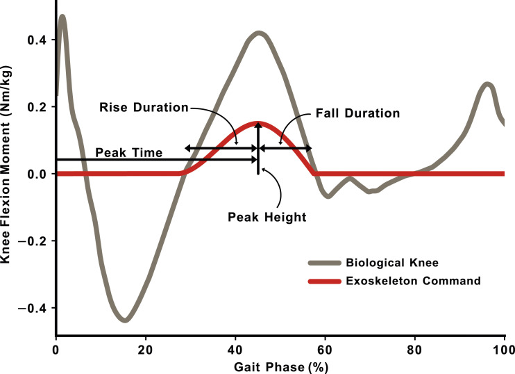
The knee exoskeleton torque controller implemented for this work was a phase-based controller adapted from previous studies of ankle exoskeleton and prosthesis torque controllers.29,30 The controller uses four parameters and a Hermite-spline technique to create a flexible torque profile that can approximate the biological knee moment during stance (Figure 5).
Figure 5.
Knee torque command parameterization for the knee exoskeleton and the average biological knee flexion moment from healthy subjects. 2 Gait phase is estimated in real-time from historical heel-strike data and is used as the domain for the commanded exoskeleton torque signal.
Low-level torque tracking controllers
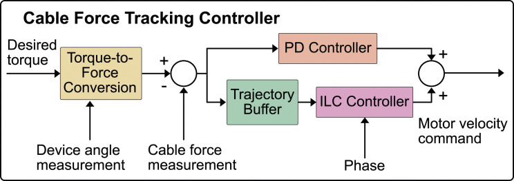
The Bowden cable transmissions have nonlinear and time-varying friction characteristics that require an adaptive compensator to overcome. 31 A cable force tracking controller was implemented for each joint that uses proportional-damping control to reject disturbances and compensate for stride-to-stride variability, and a feedforward iterative learning controller (ILC) to adapt to systematic torque errors across strides (Figure 6). The cable force tracking controller outputs a motor velocity command that is sent to a high-bandwidth motor velocity controller. Details of the controller implementation can be found in the work describing the first version of the exoskeleton. 15
Figure 6.
Expanded schematic of the cable force tracking controller. A desired torque is sent to the cable tracking controller from an upstream torque controller and transformed into the bowden cable force required to achieve the requested torque. For the knee exoskeleton and ankle-foot prosthesis, the encoder measurement is used to compute the instantaneous lever arm of the device. For the ankle-foot prosthesis, the encoder measurement is also used to estimate the torque provided by the parallel spring.
The cable force tracking controller operates at 1 kHz and the motor velocity controller operates at 1.5 MHz. The nested controller architecture is beneficial as it allows the faster motor velocity controller to sense and break the static friction in the Bowden cable by increasing motor current, and therefore makes the outer cable force tracking controller easier to tune. 32 This method of Bowden cable torque control, incorporating classical feedback and iterative learning control, has been found to be highly effective for torque tracking with wearable robots. 33
Controller hardware and software implementation
The control system for the BP is distributed across several computers. High-level prosthesis settings, for example, controller parameter and states, are controlled through a user interface via a LabVIEW program that runs on a desktop PC running Windows 10. Lossy data is streamed from the prosthesis and is displayed on the user interface for monitoring during experiments. Communication between the host PC and real-time controller is managed through an ethernet router and local area network (LAN).
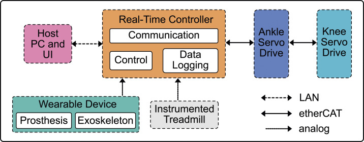
The real-time controller for the BP is a PXIe-8880 (NI, Austin, TX). The real-time controller runs a LabVIEW program that reads sensor inputs, communicates with the host PC and servo drives, and logs data. Separate parallel while-loops manage host PC communication, data logging, and control. The primary control loop is hardware-timed and deterministic, while the communication and logging loops only run intermittently. The control loop on the real-time controller implements the gait phase estimation, torque setpoint generation, and cable force tracking algorithms, and sends motor velocity commands to the servo drives. The servo drives communicate with the controller via etherCAT, a real-time communication protocol for industrial devices. The servo drives are connected to the controller in a daisy-chain setup as shown in Figure 7.
Figure 7.
Biarticular prosthesis communication and connectivity diagram. The host PC sends control parameters to and receives telemetry from the real-time controller via a local area network (LAN) and ethernet router. Signals from the wearable sensors and instrumented treadmill are read by an analog-to-digital converter on the real-time controller. Control algorithms are implemented on the real-time controller and motor velocity setpoint commands are sent to the servo drives via an etherCAT protocol.
Methods
We conducted benchtop experiments to characterize the parallel torque controllers of the knee exoskeleton and demonstrate the ability of the system to provide synchronous joint torques at the knee and ankle. We also collected walking data with one person with transtibial amputation to demonstrate the behavior of the BP.
Benchtop characterization
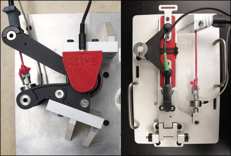
The purpose of the benchtop experiments in this study was to characterize the hardware, software, and controller performance of the BP emulator. To do this, the ankle-foot prosthesis and knee exoskeleton were mounted in rigid test stands with the joints locked in a neutral position. For the knee exoskeleton, only the actuator portion on the lateral side of the thigh was mounted, along with the actuator output and the frontal plane hinge. To improve the rigidity of the ankle-foot prosthesis mount, the carbon fiber footplate was removed and the top and bottom of the joint were both bolted directly to the test stand frame. Figure 8 shows both test stands.
Figure 8.
Photograph of the test stand setup for the ankle-foot prosthesis (left) and knee exoskeleton (right). The prosthetic footplate was removed from the prosthesis in order to efficiently lock the ankle joint. The lateral, actuated joint was removed from the knee exoskeleton for benchtop tests in order to simplify the design of the test stand.
The frequency response of the knee exoskeleton’s torque feedback controller was evaluated using sinusoidal torque setpoints. These setpoints had a static torque offset of 20 Nm and a peak-to-peak amplitude of 10 Nm, oscillating between 15 Nm and 25 Nm. The test was performed at eight oscillation frequencies ranging from 0.1 Hz to 5 Hz, with each frequency tested three times for 30 s. The iterative learning controller was disabled during this characterization. To calculate the gain and phase metrics during data analysis, the output signals were first centered at zero and fit with a sinusoidal curve of the form:
| (1) |
where A and ϕ were open optimization parameters and f and t were the input frequency in Hz and time samples for the experiment, respectively. Controller gain was computed by dividing A by 5 Nm, the input oscillation magnitude, and converted to decibels. Controller phase was defined as ϕ, as the input signal had zero phase offset.
The frequency response of the motor velocity tracking controller was evaluated using the method described above, but with no velocity offset, a peak velocity of 300 deg/s, and frequencies ranging from 0.1 Hz to 128 Hz. The motor’s velocity controller was evaluated with the Bowden cable detached.
To characterize the influence of the iterative learning controller on exoskeleton torque, a hardware-in-the-loop experiment was performed using a pre-recorded ground reaction force signal to trigger the gait phase estimation algorithm and torque setpoint generation. In the first part of the experiment, the iterative learning controller was disabled to evaluate the performance of the feedback controller alone. In the second part, the iterative learning controller was turned on until tracking was significantly improved, and then clamped, meaning the learned signal was sent as a feedforward command on each step but did not continue to update. Without clamping, the output of the iterative learning controller eventually develops high frequency “ripples.” 34 The experiment recorded 25 strides in each condition, and the average output signal was computed as a function of gait phase. The root mean squared error was computed across the 25 strides in each condition.
A series of step torque inputs were commanded to both the exoskeleton and prosthesis at the same time to demonstrate the ability to provide time-synchronized torques at the knee and ankle. Step command experiments were separated into three batches. In the first batch, the knee exoskeleton was commanded to 10 Nm and the ankle-foot prosthesis was commanded to 50 Nm. In the second batch, the exoskeleton was commanded to 20 Nm while the prosthesis was commanded to 100 Nm. In the final batch, the exoskeleton was commanded to 30 Nm and the prosthesis was commanded to 150 Nm. The step response for each setting was collected five times. Each step command started with a slight preload to remove any cable slack. In order to capture joint loading and unloading behavior, the commanded torque was held at the maximum value for one second and then returned to the preloaded value. The average step response was computed, as well as the 90% rise time, 90% fall time, and percent overshoot for each joint.
During all benchtop experiments, the PD controller gains were tuned to deliver a rapid step response with minimal overshoot and oscillation on the test stand. The controller gains appropriate for walking are too aggressive for the benchtop tests because the joint range of motion is fixed at zero. The exact ILC gains used in the iterative learning experiment are the same gains that are used during walking and were tuned by hand in pilot experiments.
Walking demonstration
One person with unilateral transtibial limb loss participated in an experiment to demonstrate the hardware and software behavior of the biarticular prosthesis in a walking environment. The participant provided written consent to take part in the study, which was approved by the Department of Veterans Affairs Puget Sound IRB (#00931). During a specific fitting visit, measurements were taken of the participant’s thigh and socket to design custom thigh and socket cuffs for the exoskeleton.
During the walking experiment, a certified prosthetist fit the COBRA ankle-foot prosthesis to the participant’s socket. Initial ankle control parameters were set based on the participant’s body mass and data from the literature. The participant walked on an instrumented treadmill with the robotic prosthesis for 5 min and the treadmill was occasionally stopped so the prosthetist could adjust the alignment of the prosthesis for comfort and walking ability. The participant then walked on the treadmill and requested a stiffer or less stiff prosthesis based on preference, and the device parameters were changed accordingly. The participant walked at 1 m/s for the experiment.
After fitting and tuning the prosthesis, the prosthetist and experimenters fit the knee exoskeleton to the participant. Initially, the participant walked with the exoskeleton in transparent mode, where the exoskeleton attempted to apply no torque to the joint. After 10 min of walking, three ten-second trials of data were logged. The exoskeleton was then turned on with a low peak torque and default timing settings, and the torque and timing parameters were tuned with the participant until they were comfortable with the exoskeleton behavior. The participant walked with a constant torque profile for 10 min and then three ten-second trials of data were logged. During data analysis, signals from the vertical GRF were used to identify heel-strikes and gait cycles were segmented, time normalized, and averaged. Signals from the wearable devices were not filtered in post processing, as they are low-pass filtered in real-time.
Results
The benchtop experiments found that the biarticular prosthesis is capable of applying sufficient joint torques at sufficient bandwidth for future walking experiments. The walking experiment showed a proof-of-concept where the prosthesis provided simultaneous knee and ankle assistance to a participant with transtibial limb loss in two modes – the knee exoskeleton behaving transparently and the knee exoskeleton providing an active torque profile.
Benchtop experiments
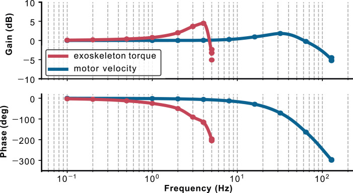
The exoskeleton torque controller and motor velocity controller’s −3 dB bandwidths were approximately 5 Hz and 100 Hz, respectively. Figure 9 shows the Bode plot for both controllers across the tested frequencies.
Figure 9.
Bode plot for exoskeleton torque and motor velocity tracking controllers. The exoskeleton torque controller shows a resonant peak near 4 Hz. Points show individually tested frequencies, and a spline connects the points for visualization.
Both controllers show characteristics of a second-order dynamical system. The exoskeleton controller shows a resonant peak near 4 Hz, which is dependent on the controller gains used in the benchtop experiments. The motor velocity shows a resonant peak at 33 Hz. The controller gains for the motor velocity controller are kept constant between the benchtop and walking environments.
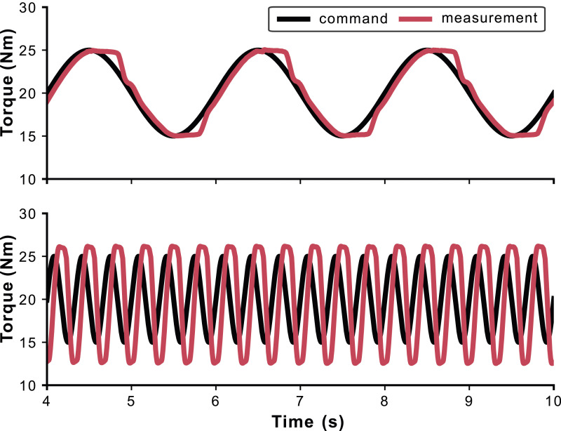
Two of the individual frequencies are shown in a time series plot in Figure 10 to show the effects of the Bowden cable nonlinearities on the cable force tracking performance. Errors are most prevalent when the commanded torque signal changes direction, for example, from loading to unloading. This is a well-known phenomenon in Bowden cable transmissions 35 and can be compensated for with iterative learning control.
Figure 10.
Torque tracking performance with two of the sinusoidal torque commands at 0.5 Hz (top) and 3 Hz (bottom). Nonlinearities due to bowden cable friction cause higher tracking errors when the loading rate changes directions.
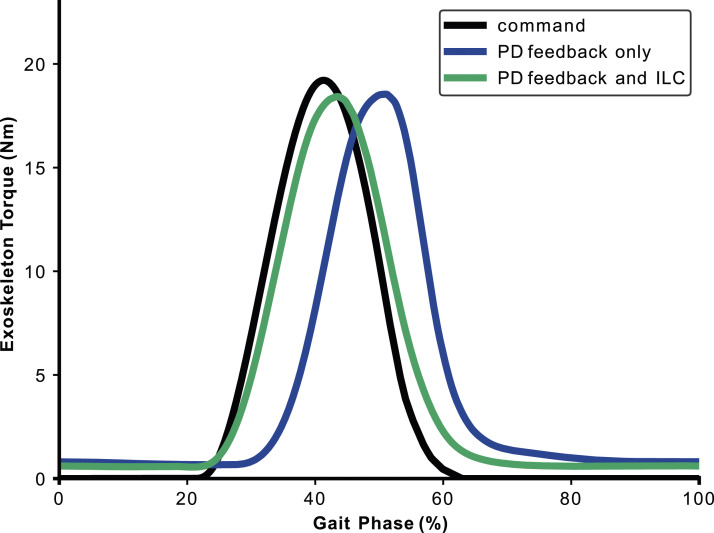
Inclusion of the iterative learning controller significantly improved tracking performance in the benchtop test. Figure 11 shows the mean torque signals over 25 strides with and without the iterative learning controller turned on. The root-mean-squared torque tracking error for the average stride was reduced from 6.04 Nm ± 0.16 Nm to 0.99 Nm ± 0.12 Nm – an 84% reduction in tracking error.
Figure 11.
Influence of the iterative learning controller as shown in the benchtop experiment. The torque command is shown in black, the proportional-damping controller (PD) in blue, and the proportional-damping controller with iterative learning control (ILC) in green. The significant phase lag in the PD controller is largely addressed by the feedforward nature of the ILC algorithm.
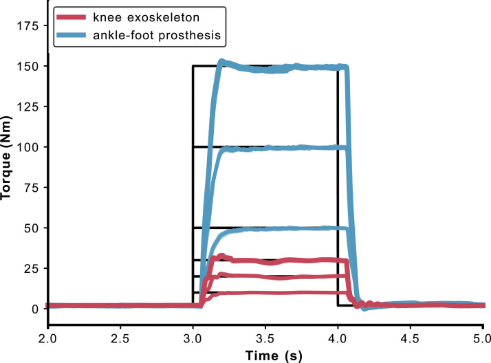
The results of the time-synchronized step response tests for the knee exoskeleton and ankle prosthesis are shown in Figure 12. The step responses were highly repeatable and showed low variability, as can be seen in Table 1. One consistent feature in the step responses for both devices is an approximately 50 ms delay between the onset of the torque command and the onset of the torque development. This delay is not observed in the motor motion following the torque command, so the delay in torque production is likely due to static friction in the Bowden cable transmission.
Figure 12.
Coordinated step responses between the ankle-foot prosthesis and knee exoskeleton. Step commands were conducted in three batches, corresponding to low, medium, and high magnitudes for each device. For a given batch, torque steps were commanded to the knee and ankle simultaneously. All five step responses are shown for each batch at both joints.
Table 1.
Step response metrics.
| Setting | Low | Medium | High |
|---|---|---|---|
| Ankle magnitude (Nm) | 50 | 100 | 150 |
| Knee magnitude (Nm) | 10 | 20 | 30 |
| Ankle rise time (ms) | 194 (8) | 169 (0) | 154 (2) |
| Knee rise time (ms) | 178 (0) | 131 (0) | 125 (0) |
| Ankle overshoot (%) | 0.66 (0.13) | 0.49 (0.16) | 1.80 (0.38) |
| Knee overshoot (%) | 1.00 (0.06) | 6.88 (1.09) | 9.82 (0.28) |
aValues in parentheses are standard deviations.
Walking results
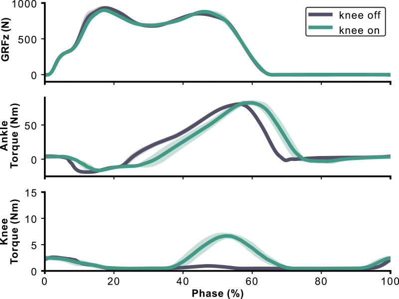
Torques from the biarticular prosthesis are shown with the vertical ground reaction force in Figure 13. The virtual heel and forefoot stiffnesses selected by the participant were 9.56 Nm/deg. and 3.10 Nm/deg., respectively. The peak knee exoskeleton torque during the transparent mode was 2.60 +/− 0.23 Nm, while the peak knee exoskeleton torque during the active mode was 6.67 +/− 0.45 Nm. This peak value is approximately 20% of the peak biological knee flexion moment for a non-disabled 80 kg subject walking at approximately 1.25 m/s2. The peak exoskeleton torque timing chosen by the participant occurred at 53% of the gait cycle. This is later than the biological knee flexion moment, which usually occurs around 45% of the gait cycle.
Figure 13.
Average measurements of the biarticular prosthesis signals during walking. The ground reaction force is shown on the top row, the prosthesis torques in the middle row, and the exoskeleton torque on the bottom row.
The participant gave positive feedback about the performance of the knee exoskeleton and preferred the behavior of the BP when the exoskeleton was active. Specifically, the participant claimed that their knee felt more stable with the assistance and that forces from the device provided them with additional proprioceptive information about the state of their limb. Figure 14 shows the participant walking in the BP.
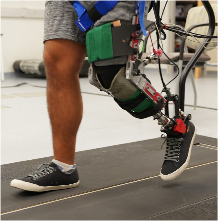
Figure 14.
The participant walking with the robotic biarticular prosthesis. As the participant moves into swing phase, the knee exoskeleton cable is nearly slacked, allowing for low joint impedance during swing.
Discussion
This work presented the design, control, and characterization of a robotic biarticular prosthesis emulator for people with transtibial limb loss. We detailed our design choices, including the rationale for developing an emulator with two independently actuated joints, and the torque control system for the device. We also presented benchtop data that characterized the actuators and control systems of the BP emulator and provided data from a simple walking demonstration with one participant.
Design choices play a critical role in the success of any lower-limb assistive device. Our BP design incorporates both standard and customizable components to allow for a high level of flexibility in sizing and fit. The strut lengths and thermoformed cuff geometries can be tailored to each user, while adjustable straps provide additional fine-tuning of the fit. Additionally, our simple and lightweight end-effectors can be easily reconfigured or even redesigned if necessary, as they are attached to an offboard actuator rather than being integrated into an autonomous, untethered prototype. This approach allows us to focus on the design and functionality of the BP through rapid experiments rather than the more complex challenges of building an untethered device. Overall, these design choices contribute to the versatility of our BP emulator.
The results of the benchtop experiments and walking trial demonstrate the feasibility of the BP emulator as a tool for studying new classes of assistive devices that incorporate gastrocnemius-like assistance for people with transtibial amputation. The benchtop experiments showed that the BP has sufficient torque and bandwidth for future walking experiments but requires the iterative learning controller to compensate for nonlinear Bowden cable friction, similar to other Bowden cable-based devices.17,36 The results of the walking trial showed that the BP was capable of providing simultaneous knee and ankle assistance to the participant during walking. The participant reported feeling more stable and having additional proprioceptive information about their limb while using the BP, suggesting that the device could be helpful in improving walking performance and stability. However, the walking results in this paper are only a preliminary demonstration of the device’s capabilities rather than an exploration of how a BP might affect the gait of people with limb loss. Further studies will be needed to fully understand the impact of the BP on walking performance and stability.
Using an emulator allows for efficient exploration of the design space of BPs. This is because the emulator can be programmed to test a wide range of designs and behaviors, including fully robotic devices, fully passive devices, and quasi-passive devices at each joint. By testing these various designs using an emulator, we can more easily identify the most effective design and control strategies for an untethered BP, rather than spending time and resources building and testing a variety of untethered BPs. Our prior work has shown that the COBRA ankle-foot prosthesis can deliver ankle push-off power similar to other powered prostheses, 26 indicating that the BP emulator is capable of emulating devices in all quadrants of the design matrix in Figure 1. For example, future work may emulate quasi-passive BP devices16,19 using our device’s joint encoder signals within an impedance controller and virtual clutch that changes its behavior based on gait events. Overall, using a BP emulator allows for a cost- and time-effective and efficient way to develop and test biarticular prostheses.
Other research groups have also developed BPs to provide knee flexion assistance to TTAs. For example, our research group previously developed an autonomous BP that combined a knee orthosis with a passive ankle prosthesis.18,19 The device used a clutched biarticular spring to provide gastrocnemius-like torque to the ankle and knee during stance and minimal torque during swing. However, the device was not optimized for comfort, and it was difficult to make changes to the device behavior without substantial hardware redesigns. Another research group at MIT developed two versions of a BP – the first was quasi-passive and also used a clutch, but with an autonomous powered ankle prosthesis. 16 The second device used a powered knee exoskeleton with the same ankle prosthesis. 17 Both devices showed promising results with preliminary walking experiments, including substantial decreases in metabolic cost in some participants. Ziemnicki et al. developed a BP using two Humotech offboard actuators – one ‘artificial soleus’ and one ‘artificial gastrocnemius,’ the latter of which physically crosses both the knee and ankle. 20 Their device is unique in that it uses soft exosuit technology instead of a knee exoskeleton, which is lightweight and comfortable, but does not have a joint encoder at the knee. The lack of real-time measurement of the knee angle limits the types of control schemes that can be effectively implemented. Overall, each of these approaches are valid ways to design BPs and the diversity of design choices helps to improve the likelihood that the field as a whole will uncover beneficial designs. As with standard uniarticular prostheses, there is likely no single universally optimal design, as patients have a wide variety of needs that can be best met with a variety of passive, quasi-passive, and powered devices.
One limitation of the current BP is the relatively low torque tracking bandwidth, which may impact the ability to emulate certain device embodiments. For example, emulating a clutch requires rapid changes in joint torque, which may be challenging with the current controller performance. Additionally, the low bandwidth of the classical feedback controller makes the overall torque tracking behavior of the BP more reliant on the iterative learning controller, which is prone to poor behavior in the event of false heel strikes, for example, in the event of the user’s feet crossing the instrumented treadmill belts. The current study only presented data from one subject in a simple experiment, so further studies with a larger number of subjects will be necessary to understand the potential benefits and limitations of the BP emulator.
In terms of future work, engineering improvements will be made to the BP emulator to improve its torque tracking bandwidth. This could be achieved by choosing wearable sensors with lower signal-to-noise ratios, increasing the sampling frequency of the controller, and optimizing the real-time low-pass filter parameters. These changes would allow for more aggressive gains to be used in the feedback controller. Additionally, further experiments will be conducted with more participants to optimize device performance through human-in-the-loop optimization algorithms. These experiments may involve comparing the optimized performance of uniarticular prostheses to biarticular ones and using the results to understand the effects of knee assistance. Other experiments may compare different device embodiments, for example, exploring how emulated quasi-passive devices compare to active ones. Finally, further experiments may also be conducted at various slopes and speeds to understand the contexts in which a BP may be more advantageous than a standard ankle-foot prosthesis.
BPs can potentially improve the life of people with limb loss in the short term by making walking easier and less painful and in the long term by reducing secondary musculoskeletal comorbidities like knee arthritis and lower back pain that are associated with gait asymmetries. The biarticular prosthesis emulator presented here will aid researchers in developing new design and control strategies for BPs and may help us understand some of the inherent limitations of our current uniarticular prostheses.
Conclusion
In conclusion, the development of biarticular prostheses has the potential to greatly improve the gait patterns and musculoskeletal health of individuals with limb loss. The BP emulator presented in this study is a promising tool towards this end, as it allows for the simultaneous assistance of both the knee and ankle during walking. Through the use of an offboard motor and emulator, the BP was able to provide synchronous joint torques with sufficient bandwidth for future walking experiments. While further engineering improvements and testing with additional participants are needed, the BP emulator shows promise as a tool for improving the gait patterns and overall mobility of individuals with limb loss.
Acknowledgements
The authors thank Christina Carranza, CPO, for her feedback on device design as well as fitting the biarticular prosthesis to the participants.
Footnotes
Author contributors: AA and PA conceived of the device and the study. AA and KG designed the knee exoskeleton hardware. AA developed all emulator software. AA, BM, and PA designed the experimental protocols. BM managed ethics approvals and patient recruitment. AA, KG, MSV, KN, and BM collected all experimental data. AA analyzed the experimental data and wrote the manuscript. All authors critically reviewed the manuscript and approved the final version.
The author(s) declared no potential conflicts of interest with respect to the research, authorship, and/or publication of this article.
Funding: The author(s) disclosed receipt of the following financial support for the research, authorship, and/or publication of this article: This work was funded by VA RR&D grants A9243C, RX002357, and RX002130, as well as the VA Puget Sound Predoctoral Training Award.
Guarantor: AA
ORCID iD
Anthony J Anderson https://orcid.org/0000-0002-8052-7069
References
- 1.Srisuwan B, Klute GK. Locomotor activities of individuals with lower-limb amputation. Prosthet Orthot Int 2021; 45(3): 191–197. [DOI] [PMC free article] [PubMed] [Google Scholar]
- 2.Ferris AE, Aldridge JM, Rábago CA, et al. Evaluation of a powered ankle-foot prosthetic system during walking. Arch Phys Med Rehabil 2012; 93(11): 1911–1918. DOI: 10.1016/j.apmr.2012.06.009. [DOI] [PubMed] [Google Scholar]
- 3.Gailey R, Allen K, Castles J, et al. Review of secondary physical conditions associated with lower-limb amputation and long-term prosthesis use. J Rehabil Res Dev 2008; 45(1): 15–29. DOI: 10.1682/JRRD.2006.11.0147. [DOI] [PubMed] [Google Scholar]
- 4.Kulkarni J, Gaine WJ, Buckley JG, et al. Chronic low back pain in traumatic lower limb amputees. Clin Rehabil 2005; 19(1): 81–86. DOI: 10.1191/0269215505cr819oa. [DOI] [PubMed] [Google Scholar]
- 5.Norvell DC, Czerniecki JM, Reiber GE, et al. The prevalence of knee pain and symptomatic knee osteoarthritis among veteran traumatic amputees and nonamputees. Arch Phys Med Rehabil 2005; 86(3): 487–493. DOI: 10.1016/j.apmr.2004.04.034. [DOI] [PubMed] [Google Scholar]
- 6.Kim J, Wensman J, Colabianchi N, et al. The influence of powered prostheses on user perspectives, metabolics, and activity: a randomized crossover trial. J NeuroEng Rehabil 2021; 18(1): 49. DOI: 10.1186/s12984-021-00842-2. [DOI] [PMC free article] [PubMed] [Google Scholar]
- 7.Clark WH, Pimentel RE, Franz JR. Imaging and simulation of inter-muscular differences in triceps surae contributions to forward propulsion during walking. Ann Biomed Eng 2020; 49(2): 703–715. DOI: 10.1007/s10439-020-02594-x. [DOI] [PMC free article] [PubMed] [Google Scholar]
- 8.Francis CA, Lenz AL, Lenhart RL, et al. The modulation of forward propulsion, vertical support, and center of pressure by the plantarflexors during human walking. Gait Posture 2013; 38(4): 993–997. DOI: 10.1016/j.gaitpost.2013.05.009. [DOI] [PMC free article] [PubMed] [Google Scholar]
- 9.Liu MQ, Anderson FC, Pandy MG, et al. Muscles that support the body also modulate forward progression during walking. J Biomech 2006; 39(14): 2623–2630. DOI: 10.1016/j.jbiomech.2005.08.017. [DOI] [PubMed] [Google Scholar]
- 10.McGowan CP, Neptune RR, Kram R. Independent effects of weight and mass on plantar flexor activity during walking: implications for their contributions to body support and forward propulsion. J Appl Physiol 2008; 105(2): 486–494. DOI: 10.1152/japplphysiol.90448.2008. [DOI] [PMC free article] [PubMed] [Google Scholar]
- 11.Neptune RR, Kautz SA, Zajac FE. Contributions of the individual ankle plantar flexors to support, forward progression and swing initiation during walking. J Biomech 2001; 34(11): 1387–1398. DOI: 10.1016/S0021-9290(01)00105-1. [DOI] [PubMed] [Google Scholar]
- 12.Zmitrewicz RJ, Neptune RR, Sasaki K. Mechanical energetic contributions from individual muscles and elastic prosthetic feet during symmetric unilateral transtibial amputee walking: a theoretical study. J Biomech 2007; 40(8): 1824–1831. DOI: 10.1016/j.jbiomech.2006.07.009. [DOI] [PubMed] [Google Scholar]
- 13.Russell Esposito E, Wilken JM. Biomechanical risk factors for knee osteoarthritis when using passive and powered ankle–foot prostheses. Clin Biomech 2014; 29(10): 1186–1192. DOI: 10.1016/j.clinbiomech.2014.09.005. [DOI] [PubMed] [Google Scholar]
- 14.Silverman AK, Neptune RR. Muscle and prosthesis contributions to amputee walking mechanics: a modeling study. J Biomech 2012; 45(13): 2271–2278. DOI: 10.1016/j.jbiomech.2012.06.008. [DOI] [PubMed] [Google Scholar]
- 15.Anderson AJ, Hudak YF, Gauthier KA, et al. Design and evaluation of a knee flexion assistance exoskeleton for people with transtibial amputation. In: 2022 international conference on rehabilitation robotics (ICORR), Rotterdam, Netherlands, 25–29 July 2022, 1–6. DOI: 10.1109/ICORR55369.2022.9896485. [DOI] [PubMed] [Google Scholar]
- 16.Eilenberg MF, Endo K, Herr H. Biomechanic and energetic effects of a quasi-passive artificial gastrocnemius on transtibial amputee gait. J of Rob 2018; 2018: 1–12. DOI: 10.1155/2018/6756027. [DOI] [Google Scholar]
- 17.Eilenberg MF, Kuan JY, Herr H. Development and evaluation of a powered artificial gastrocnemius for transtibial amputee gait. J of Rob 2018; 2018: 1–15. DOI: 10.1155/2018/5951965. [DOI] [Google Scholar]
- 18.Willson AM, Richburg CA, Anderson AJ, et al. Evaluation of a quasi-passive biarticular prosthesis to replicate gastrocnemius function in transtibial amputee gait. J Biomech 2021; 129: 110749. DOI: 10.1016/j.jbiomech.2021.110749. [DOI] [PMC free article] [PubMed] [Google Scholar]
- 19.Willson AM, Richburg CA, Czerniecki J, et al. Design and development of a quasi-passive transtibial biarticular prosthesis to replicate gastrocnemius function in walking. J Med Dev Trans ASME 2020; 14(2): 0250011–0250016. DOI: 10.1115/1.4045879. [DOI] [PMC free article] [PubMed] [Google Scholar]
- 20.Ziemnicki DM, Caputo JM, McDonald KA, et al. Development and evaluation of a prosthetic ankle emulator with an artificial soleus and gastrocnemius. J Med Dev Trans ASME 2021; 15: 4052518. DOI: 10.1115/1.4052518. [DOI] [Google Scholar]
- 21.Ziemnicki DM, McDonald KA, Wolf DN, et al. Combining an artificial gastrocnemius and powered ankle prosthesis: effects on transtibial prosthesis user gait. J Biomech Eng 2023; 145: 061009. DOI: 10.1115/1.4056706. [DOI] [PubMed] [Google Scholar]
- 22.Caputo JM, Collins SH. A universal ankle-foot prosthesis emulator for human locomotion experiments. J Biomech Eng 2013; 136(3): 035002. DOI: 10.1115/1.4026225. [DOI] [PubMed] [Google Scholar]
- 23.Farris DJ, Sawicki GS. Human medial gastrocnemius force–velocity behavior shifts with locomotion speed and gait. Proc Natl Acad Sci USA 2012; 109(3): 977–982. DOI: 10.1073/pnas.1107972109. [DOI] [PMC free article] [PubMed] [Google Scholar]
- 24.Neptune RR, Sasaki K, Kautz SA. The effect of walking speed on muscle function and mechanical energetics. Gait Posture 2008; 28(1): 135–143. DOI: 10.1016/j.gaitpost.2007.11.004. [DOI] [PMC free article] [PubMed] [Google Scholar]
- 25.Lenhart RL, Francis CA, Lenz AL, et al. Empirical evaluation of gastrocnemius and soleus function during walking. J Biomech 2014; 47(12): 2969–2974. [DOI] [PMC free article] [PubMed] [Google Scholar]
- 26.Anderson AJ, Hudak YF, Muir BC, et al. Design, control, and evaluation of a robotic ankle-foot prosthesis emulator. IEEE Trans Med Robot Bionics 2023; 5(3): 741–752. DOI: 10.1109/TMRB.2023.3291015. [DOI] [Google Scholar]
- 27.Witte KA, Fatschel AM, Collins SH. Design of a lightweight, tethered, torque-controlled knee exoskeleton. IEEE Int Conf Rehabil Robot 2017; 2017: 1646–1653. DOI: 10.1109/ICORR.2017.8009484. [DOI] [PubMed] [Google Scholar]
- 28.Wang J, Li X, Huang T, et al. Comfort-centered design of a lightweight and backdrivable knee exoskeleton. IEEE Rob Autom Lett 2018; 3(4): 4265–4272. DOI: 10.1109/LRA.2018.2864352. [DOI] [Google Scholar]
- 29.Zhang J, Fiers P, Witte KA, et al. Human-in-the-loop optimization of exoskeleton assistance during walking. Science 2017; 356(6344): 1280–1284. [DOI] [PubMed] [Google Scholar]
- 30.Welker CG, Voloshina AS, Chiu VL, et al. Shortcomings of human-in-the-loop optimization of an ankle-foot prosthesis emulator: a case series. R Soc Open Sci 2021; 8(5): 202020. DOI: 10.1098/rsos.202020. [DOI] [PMC free article] [PubMed] [Google Scholar]
- 31.Dongyang Chen AD, Youngmok Yun AD, Deshpande AD. Experimental characterization of bowden cable friction. In: IEEE international conference on robotics and automation, Hong Kong, China, 31 May 2014–07 June 2014, pp. 5927–5933. IEEE. DOI: 10.1109/ICRA.2014.6907732. [DOI] [Google Scholar]
- 32.Pratt G, Willisson P, Bolton C, et al. Late motor processing in low-impedance robots: impedance control of series-elastic actuators. In: Proceedings of the 2004 American control conference, Boston, MA, 30 June 2004–02 July 2004. pp. 3245–3251. DOI: 10.23919/ACC.2004.1384410. [DOI] [Google Scholar]
- 33.Zhang J, Cheah CC, Collins SH. Experimental comparison of torque control methods on an ankle exoskeleton during human walking. In: International conference on robotics and automation, Seattle, WA, 26–30 May 2015, pp. 5584–5589. IEEE. DOI: 10.1109/ICRA.2015.7139980. [DOI] [Google Scholar]
- 34.Zhang J, Cheah CC, Collins SH. Chapter 5 - torque control in legged locomotion. In: Sharbafi MA, Seyfarth A. (eds) Bioinspired legged locomotion. Oxford, UK: Butterworth-Heinemann, 2017, pp. 347–400. DOI: 10.1016/B978-0-12-803766-9.00007-5. [DOI] [Google Scholar]
- 35.Li X, Liu J, Li W, et al. Force transmission analysis and optimization of bowden cable on body in a flexible exoskeleton. Appl Bionics Biomech 2022; 2022: e5552166. DOI: 10.1155/2022/5552166. [DOI] [PMC free article] [PubMed] [Google Scholar]
- 36.Bryan GM, Franks PW, Klein SC, et al. A hip–knee–ankle exoskeleton emulator for studying gait assistance. Int J Robot Res 2021; 40(4–5): 722–746. DOI: 10.1177/0278364920961452. [DOI] [Google Scholar]


