Abstract
Aiming at the problem that an Interior Permanent Magnet Synchronous Motor (IPMSM) cannot be smoothly started in zero-low speed range and smoothly transitioned to medium-high speed range by a single observer. This paper proposes a full-speed range control algorithm based on the fusion of pulsating high-frequency injection and back electromotive force (EMF) position error information. In the low-speed range or at start-up, a square-wave high-frequency signal is injected, and the obtained high-frequency current signal is processed to obtain the rotor position error information. The phase shift due to the introduction of a filter is reduced, which improves the control bandwidth and reduces the noise. To ensure smooth switching of the observer, the observer uses a dual second-order generalized integrator module to output the angular frequency in the low-speed range. A higher-order sliding mode observer based on an inverse EMF model obtains rotor position error information at high speeds. During switching, the rotor position information is processed by a fusion strategy, and the obtained hybrid information is fed into the system to improve the stability of the motor operation. A 0.2 kW IPMSM position sensorless vector control system verifies the algorithm’s accuracy.
Keywords: IPMSM, Full speed range position sensorless control, High frequency injection, HSMO, Novel fusion strategy
Subject terms: Electrical and electronic engineering, Mechanical engineering
Introduction
IPMSM has become the best choice for industry, especially in electric drives and precision manufacturing, due to its power and stability1,2. Conventional motor vector control systems use mechanical position sensors to obtain effective speed and rotor position information in real time, increasing cost and system complexity. In addition, the service life and measurement accuracy of mechanical sensors are significantly reduced due to concentricity issues during installation and interference from environmental factors such as temperature, humidity, and vibration. Therefore, field-oriented control (FOC) algorithms based on magnetic field direction have received extensive attention and research, and this method can reduce the complexity of the IPMSM systems, decrease overhead, extend the service life, and improve measurement accuracy, which is of excellent research significance3. There has been much in-depth research on position sensorless algorithms for IPMSM at home and abroad. According to the speed range, the research results can be categorized into zero-low and high-speed ranges. During startup or low-speed range operation, most of the position information is obtained by the internal convex polarity of the motor. A high-frequency signal consisting of a sine wave or a square wave is usually injected4,5. However, conventional high-frequency voltage injection methods produce audible noise due to the high injection frequency, which limits the practical application of the high-frequency voltage injection methods6. When the IPMSM operates in the high-speed domain, a sliding mode observer (SMO) extended Kalman filter based on the inverse EMF method can be used to obtain the rotor angle of the motor.
The sensorless motor runs stably throughout the process, and the above two observer algorithms can be fused and used to form a sensorless hybrid control system. In recent years, the research on sensorless hybrid control technology has progressed. Literature 7 proposes a high-frequency pulsed voltage signal injection method based on enhanced linear active disturbance rejection control (LADRC)7. The method establishes a cascaded extended state observer to ensure a relatively timely and accurate estimation of the total disturbance. However, the method relies too heavily on parameter tuning and does not apply to complex systems. In literature 8, Dingdou Wen proposed an improved sliding mode observer method for estimating motor speed and rotor position information in the medium and high-speed ranges8. The rotating high-frequency voltage signal injection method is used in the low-speed ranges. However, the method has to introduce a low-pass filter, which can lead to inaccurate phase shift and angle observations. Literature 9 proposes a hybrid active flux observer with interference suppression is proposed for the high-frequency signal injection method and the model-based method to suppress the position estimation error9. In addition, a stator resistance identification algorithm is proposed to improve the algorithm’s performance at low speeds. Literature 10 applies the high-frequency method to the motor starting and low-speed inductorless control algorithms and uses an adaptive system approach for the high-speed operation of the PMSM10. Literature 11 uses a strategy combining the control constant voltage/frequency tuning method and SMO to get the position sensorless control of the motor throughout the operating state11. Literature 12 introduces a novel discrete SMO to detect the rotor position, which is full-order multiple-input and multiple-output12. Literature 13 proposes a novel hybrid rotor position observer that combines a high-frequency injection (HFI) method with a flux observer, which uses a Luenberger-type stator flux observer13. Literature 14 combines the AC test current injection method and model-based dynamic feedforward control14. While literature 15 uses a combination of the high-frequency signal injection method and inverse electromotive force sliding mode observer method15, this method commutates the motor at zero speed operation, and the observer will diverge and cannot track the proper angle of the rotor in real-time. Moreover, due to the non-smoothness of the switching function, the switching of the observer still occurs with the transient phenomenon of the motor emitting strange noise.
Existing hybrid control algorithms mainly use rotor position information fusion, and although they have achieved stage-by-stage experimental results, they still have some drawbacks. In order to optimize the hybrid control strategy and its practicability further, it is still necessary to investigate the problems of these two methods in terms of fusion method and robustness. Therefore, in this paper, a sensorless control algorithm for IPMSM full-speed range position based on a hybrid observer with a novel fusion strategy is proposed as follows:
Since the motor is at a low speed, a phase shift occurs when using a Low-pass filter (LPF). The angular frequency of the rotor also changes when a high-frequency signal is injected. In order to solve these problems, this paper improves the injection method of pulsed high-frequency square-wave signals; the square-wave signal is injected into the rotating coordinate system, the position information and angular frequency are extracted from the rotating coordinate system, and the -axis current calculation is changed to a differential signal, which reduces the use of low-pass filters and improves the system’s bandwidth.
This paper proposes an improved DSOGI system to solve the problem that a bandpass filter (BPF) cannot remove high-frequency signals. It also improves the system’s dynamic performance and prevents motor startup jitter. In addition, In addition, tuning parameters is more advantageous than the traditional method.
In this paper, the pulsation high-frequency square-wave injection method is combined with the EMF method, and a full-speed range fusion strategy is used in the context of higher-order functions. When switching the observer, the algorithm adopts the coefficient method to fuse the rotor error information with the speed signal, ensuring the motor’s smooth switching during speed-up and realizing the full speed range position sensorless control.
IPMSM position sensorless control method
Pulsating high frequency voltage signal injection method
Equation (1) about voltage for IPMSM can be written in the rotation coordinate system
| 1 |
Where: , are the stator voltage and , are the current components under the rotating coordinate system; and are the motor electric angular frequency and permanent magnet magnetic chain, respectively; , are the stator inductance; and is the motor stator resistance. When the IPMSM operating state is in zero-low speed range operation, the operating frequency of the injected voltage is larger than the motor’s electrical corner frequency16; at this time, the IPMSM is equivalent to a purely inductive model, so Eq. (1) can be rewritten as
| 2 |
Where: , are the high frequency voltage and , are current components under the rotating coordinate system; and are the high frequency inductance.
The positions between the stationary coordinate system, the estimated rotational coordinate system, and the real rotational coordinate system are shown in Fig. 1, where , , are the estimated position angle, the actual motor rotor position angle, and the difference between them, respectively.
Fig. 1.
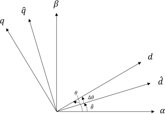
Diagram of angles between frames of reference.
The high-frequency voltage response of the rotation can be described by Eq. (3)
| 3 |
in Eq. (3) is the transformation matrix, and the current response in the frame of reference can be described as:
| 4 |
Substituting Eq. (2) into Eq. (4) yields
| 5 |
A high-frequency voltage signal is injected into the estimated rotational -axis coordinate system.
| 6 |
However, this injection voltage frequency depends on the control frequency. Since the estimated -axis signal determines it, it has a decisive influence on the performance of the motor drive.
Although high-frequency signals can be injected into any coordinate system, injection into a rotating coordinate system makes the system more stable and facilitates position extraction. If the high-frequency signal is injected into the estimated coordinate system, the injected voltage and the voltage signal in the rotating reference system can be described as
| 7 |
in Eq. (7). denotes an injected high frequency square signal not restricted to the paper.
In the high-frequency square-wave injection method proposed in this paper, although the voltage signal under the rotating coordinate system determines the generation of high-frequency voltages, it will be multiplied by the current of the rotating coordinate system when it enters the signal modulation and finally feeds into the phase-locked loop. The position angle is obtained through the high-frequency square-wave injection observer. Since there are no additional BPFs and LPFs to cause time delays that would affect the rotor angle accuracy, we can significantly increase the angular frequency of the high-frequency signal. The block diagram of the high-frequency signals generated is shown in Fig. 2. The algorithm does not introduce any filter, ensuring a high degree of phase consistency.
Fig. 2.
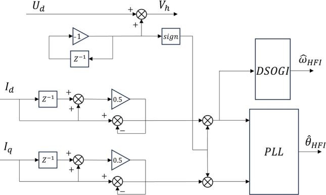
Flowchart of square wave voltage generation.
High frequency signal extraction
Due to the apparent cross-saturation effect, the rotor position does not generate an estimation error after the high-frequency signal flows into the estimated rotating coordinate system. Therefore, the induced current is generated only in the -axis, and the position information of its estimation can be processed as follows: substituting Eq. (2) into Eq. (3) and rewriting it to get
| 8 |
Substituting Eq. (7) into Eq. (8) reduces to
| 9 |
Transforming Eq. (9) into the estimated rotating reference system gives Eq. (10).
| 10 |
From Eq. (10), it can be seen that the high-frequency current of the -axis rotating coordinate system is proportional to the angular error
| 11 |
When converges infinitely to 0, Eq. (11) can be equated as
| 12 |
However, a conventional sinusoidal signal will become 0 every half cycle, resulting in Eq. (12) having non-computable points at each cycle. In this case, it is possible to inject the signal using a square wave and replace the current derivative operation on the -axis with a differential operation on the sampled current, in which case the rotor angle error can be rewritten as
| 13 |
where is the system period, is the differential current
| 14 |
In electric corner frequency extraction, DSOGI can lock the high-frequency signal to a particular frequency because the performance and stability of the system should be improved. Taking the frequency used in this paper as the reference frequency, as described in Fig. 3, can be derived according to the closed-loop equation
| 15 |
where , , for the sake of system stability , is the system frequency.
Fig. 3.
Block diagram of DSOGI process.
Observation method based on inverse electromotive force modeling
Conventional sliding film observers generate large amounts of high-frequency switching ripples even after filtering, They cannot commute quickly at high speeds due to the nature of the observer itself. However, using an HSMO greatly compensates for such a shortcoming and eliminates the need to add a filter after the observation result. First, the motor voltage equation in the stationary coordinate system is given
| 16 |
| 17 |
where is the differential operator, and are the extended inverse potentials.
Since can be considered more stable in the running state of the motor, its derivative can be treated as 0. Simplifying Eq. (17) yields
| 18 |
| 19 |
Then the HSMO is designed as follows
| 20 |
Subtracting the observer equation from the actual motor equation yields
| 21 |
where denotes sign, which is the sign-taking function. Select the Lyapunov function to verify its stability
| 22 |
| 23 |
If the observer is expected to be stable, we need , which is calculated as
| 24 |
Substituting Eq. (24) back into Eq. (21) yields
| 25 |
The final solution is that the observer is stable when .
When the motor is working at high speed, the angle information of the rotor is output through the phase-locked loop, and the structure is shown in Fig. 4.
Fig. 4.
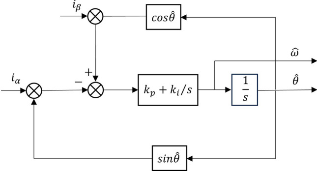
Rotor angle solution diagram.
The rotor position signal can be obtained from Fig. 4, as shown below
| 26 |
When and are very close, Eq. (26) can be rewritten
| 27 |
In this case, the frequency-domain expression of the phase-locked loop is
| 28 |
When the and are positive, the system is stable, the phase-locked loop can estimate the angle efficiently, and the algorithm approximates the angle to the actual value of the motor.
Hybrid observer design without position sensor
According to the above two position sensorless control strategies, the pulsating HFI method is used when the motor starts or rotates at low speeds, and the HSMO method is used when the electrical angular frequency is higher than 55 rad/s. Some scholars have proposed a fusion control algorithm based on cosine switching17. However, for the pulsating HFI method switching, the nature of the cosine function will inevitably produce a small range of violent jitter in the output angle, resulting in an unsmooth motor switching and abnormal noise. The two control algorithms proposed in this paper adopt a novel fusion strategy to design a switching method with continuously smooth switching proportionality coefficients using higher-order functions. The two switching points are and , respectively, and the proposed function requirements are
| 29 |
The new allocation strategy segmentation function is found to be
| 30 |
Figure 5 depicts a block diagram of a novel rotor position control strategy incorporating the two sensorless schemes mentioned above. In order to better lock through the DSOGI module during the startup phase, the pulsating HFI method is used to obtain the position error information, and the motor angular frequency signal and rotor position error information are obtained by using the HSMO in the high-speed range stage. The rotor position estimates and the electrical angular frequency are and for the pulsating HFI method, and for the HSMO.
Fig. 5.
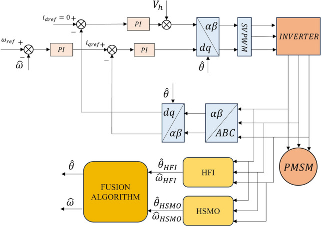
Block diagram of full speed range hybrid observer structure.
When the electrical angular frequency of the motor is in the transition phase of a given threshold, the two observers jointly determine the output parameters. The assignment strategy is shown in Fig. 6.
Fig. 6.
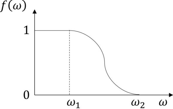
Allocation strategy function.
According to the corresponding coefficients in Fig. 6, the estimated position and angular frequency within the system are summed by Eq. (31) to obtain the motor’s final estimated position and angular frequency.
| 31 |
The initial stage of the system uses the pulsating HFI method and the HSMO to run simultaneously. However, at this time, only the rotor error signal and electrical angle frequency signal generated by the pulsating HFI method are used. When the motor speeds up to the threshold , the switching mode is turned on, and the system will use the rotor error signal and electrical angle frequency generated by the fusion algorithm. When the motor speed exceeds the state, the system will entirely switch to HSMO operation mode, at which time the pulsed HFI method will be deactivated and decelerated. Finally, the estimated position will be sent into the coordinate change, and the electrical angle frequency will be sent into the speed loop for vector control. In this way, the computing burden of the MCU can be effectively alleviated and the computation time can be shortened.
Analysis of experimental results
The position sensorless hybrid algorithm is validated in a 0.2kW IPMSM control system as described in Fig. 7; the load test is performed using a motor-to-drag approach with the motor parameters described in Table 1.
Fig. 7.
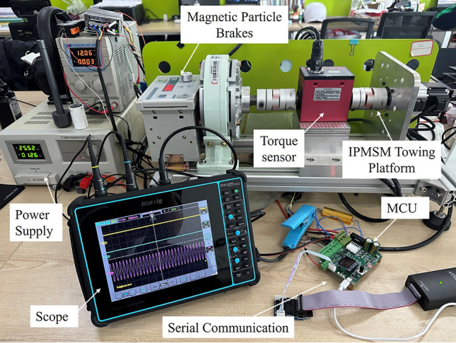
Description of the test bench.
Table 1.
Motor parameters.
| Parameters | Value |
|---|---|
| Stator resistance / | 0.09238 |
| d-axis inductors/H | 0.000197 |
| q-axis inductors/H | 0.000257 |
| d-axis inductors/H | 0.000197 |
| Flux Linkage/Wb | 0.098 |
| Pole Number | 5 |
| Rated Voltage/V | 24 |
| Rated Current /A | 9.5 |
| Rated Speed/rpm | 3000 |
| Rated Torque/N M | 0.64 |
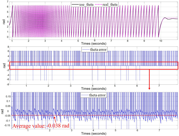
The sampling frequency of the system is 10kHz, and the pulsating high-frequency voltage is injected with an amplitude of 1.25 V and a frequency of 1.25 kHz. The following experimental results are obtained in the host computer using a closed-loop sensorless hybrid control strategy. Figure 8 shows the experimental results of the motor starting from 0 r/min speed to 500 r/min and then decreasing to 0 r/min under 0.3 load. The three graphs show the rotor position observation value, observation error and its amplification value, respectively. From the experimental result graphs, it can be seen that the hybrid control algorithm without a position sensor proposed in this paper can meet the low-speed and high-speed operating conditions, and from the macroscopic point of view, the switching of the two algorithms is more flexible, and the information fusion of the two observers is effective. The position observation error of the system under the whole operation environment is less than rad, and the average value is rad.
Fig.8.
Experimental results of hybrid control of two sensorless methods (0-500-0 r/min).
Figure 9 compares the electrical angle frequencies generated by the pulsating HFI method after the phase-locked loop and the DSOGI module. The DSOGI still works well when processing high-frequency signals. The electrical angle frequency generated by the phase-locked loop contains more ripples, which will significantly impact the processing of the angular signal. Since the electrical angle frequency contains more ripples, the motor will be more disturbed during zero-speed startup, leading to problems such as jitter and noise or even startup failure. In addition, when the fusion algorithm intervenes, the motor will switch frequently between the two observers, leading to uneven switching. After DSOGI processing, the electric corner frequency ripple is much smaller, and the motor can start smoothly and switch successfully between the two observers.
Fig. 9.
Comparison of electrical corner frequencies.
Figure 10 shows the experimental diagram of speed tracking and a two-phase rotating coordinate system under a 0.3 . Figure 10a shows the speed tracking; when the motor receives the speed loop command, the steady state tracking of the system is stabilized within 0.7s, and the overshoot does not exceed 5, which gives an excellent dynamic performance. Figure 10b shows the current state response of the system in a two-phase rotating coordinate system from static acceleration to 100 r/min. When the motor speed increases to 0.13 s and reaches the switching threshold, the high-frequency current will not be injected into the -axis. and the step response of the -axis indicates the system’s robustness.
Fig. 10.
Dynamic response experiment under load.
Figure 11 compares the switching details of the position sensorless control system motor at 0.3 load. The selected switching points is 50 rad/s, and is 55 rad/s. Figure 11a shows the observed and actual motor position data under the cosine switching strategy. At the beginning and end stages of switching, the derivative value of the cosine function may be too large, and the periodic function will lead to the switching oscillations, making the switching process not smooth; the motor will generate noise and jitter, and the motor will be quickly out of step during switching, which ultimately makes the algorithm diverge. From Fig. 11b, it can be seen that after adopting the new allocation strategy, whether intervening or completing the switching, the smoothness of the switching is guaranteed because the function of the strategy is derivable everywhere, and the derivative of the switching place is zero. The algorithm’s position observation at the switching point changes very little. It can quickly track the actual angle of the motor, and the error between the rotor position observation and the actual value is controlled within 0.1 rad, with good results.
Fig. 11.
Experimental results of switching angle comparison.
Figure 12 presents the experimental results of the sensorless control system operating in the electric and brake switching states. When the motor is in the forward fast running state, the magnetic powder brake increases the motor load, causing the motor to run at low speed. Currently, the algorithm is in a strong convergence state, and the observed values are consistent with the true values. When a reverse current is applied to the motor, the observed and actual rotor angles are immediately output in reverse. This indicates that the motor switches at zero speed, and the algorithm converges. Subsequently, as the load increases, the motor is forced to run at a low speed in reverse. The motor remains stable, and eventually, with increased current, the motor successfully reverses. The algorithm can accurately observe the switching state of the motor and run stably.
Fig. 12.
Zero speed load experiment results.
Figure 13 shows current waveforms in a stationary coordinate system, where the striped current waveforms are mainly caused by HFI, low speed operation still ensures good sinusoidal characteristics in the event of sudden loading.
Fig. 13.
Current waveforms in a two-phase stationary reference system.
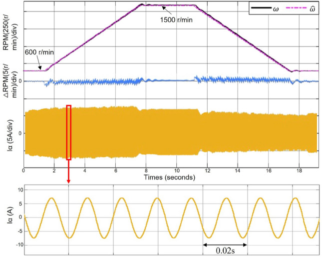
Figure 14 shows the RPM tracking command test results, where the motor speed increases from 600 to 1500 r/min at 50% load and then decreases to 600 r/min. Since the motor is in a discrete system, the speed command in this figure is a step-increasing ramp function, and therefore, the electrical angular frequency ripple is larger when the speed is changed than at a steady state. The experimental results show that with the sensorless control strategy proposed in this paper, the motor can still operate stably in the medium and high-speed domain. The error of the electrical angle frequency is within 3 r/min, the overshoot and oscillation of the system when the reference speed is changed are also within the controllable range, and the -axis current in the stationary coordinate system is a steady sine wave.
Fig. 14.
RPM tracking command test(600–1500–600 r/min).
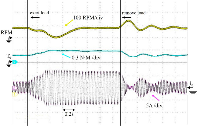
Figure 15 shows the load disturbance experiment under the running state of the motor through the magnetic powder brake to provide the motor with a fixed direction of the load torque, the figure for the torque sensor and current clamp connected to the oscilloscope, the figure from top to bottom of the three lines are speed, torque, and current waveforms. At this time, the motor to 550 r/min constant speed work, to the motor to apply 0.3 load, from the blue line can be seen from the motor output torque becomes larger, the speed loop can quickly respond to the completion of the second-order speed within 1s system stabilization, the phase current input to the motor can be quickly corresponding within 0.4s. On the contrary, when the motor is unloaded, it can be seen from the figure that the system responds quickly, without delay, and with less oscillation, This situation arises because the system does not use the LPF or the BPF to limit the system bandwidth.
Fig. 15.
Load disturbance experiment.
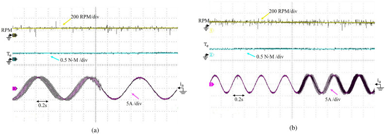
Figure 16 shows the experimental results of switching between the pulsating HFI and the HSMO methods using the sensorless control system in an oscilloscope under motor load. Figure 16a shows that the system is switched from pulsating HFI method to HSMO, and there is no change in torque and speed before and after the switching, proving that the system can maintain a stable speed and the fusion algorithm can switch smoothly. Figure 16b shows that when switching from HSMO mode to pulsating HFI mode, the torque and speed still have no fluctuation, and the system is stable. From these two graphs, the algorithm can ensure that the phase currents are sinusoidal waveforms without distortion, no matter how switched.
Fig. 16.
Observer switching experiment.
Figure 17 measured the consumption time of the improved fusion algorithm using an oscilloscope and compared it with other algorithms. The control frequency proposed in this paper is 10kHz, which pulls the level up when entering the execution cycle of the algorithm and pulls it down when the algorithm is finished.
Fig. 17.
Comparison chart of algorithmic time consumption.
The left figure shows that the proposed algorithm consumes 26 µs before switching due to the simultaneous operation of the two observers. After switching due to the de-energization of the high-frequency square-wave injection method, the computational burden of the MCU is reduced, and only 20 µs are needed to complete the computation. The figure on the right shows the algorithm before improvement, and without deactivating the previous observer after switching, the algorithm consumes 31 µs. The proposed improved algorithm not only improves the time under the simultaneous operation of two observers compared to the previous one but also consumes less time for a single observer after switching.
Conclusion
In this paper, an IPMSM sensorless system based on the fusion of rotor position error information is investigated, which is analyzed and obtained based on the proof of principle and experimental results:
Adding the DSOGI module into the system can remove the ripple caused by the high-frequency quantity and efficiently lock the motor’s electric omega frequency, which not only avoids the abnormal noise and vibration when the motor starts but also lays the foundation for the subsequent smooth switching.
The sensorless full-speed domain operation of the motor is realized by a novel fusion strategy that fuses the position error information and the electrical angle frequency signal from the pulsating high-frequency square wave injection method and the inverse potential method. Only one phase-locked loop is required to obtain the hybrid position observations, which is simple and efficient, and smooth switching between the two observers between the two observers can be realized using this method.
The sensorless hybrid control algorithm proposed in this paper performs well in the zero-speed and high-speed ranges. The experimental results show that the pulsating HFI method can make the IPMSM converge quickly at startup, keep the system stable in low-speed operation, generate high-frequency currents with sinusoidal bands, and switch to the high-speed range; the motor can also switch smoothly run stably with the load.
Author contributions
Y.G. came up with the idea for this article. S.Y. performed data matching with parameters provided. M.T. conducted tests and data analysis. Y.G. and J.C. analyzed the results. Y.G. and Q.C. prepared and revised the manuscript. All authors reviewed and finalized the draft.
Funding
This study was supported by the National Natural Science Foundation of China (62071331).
Data availability
The data that supports the findings of this study are available within the article.
Competing interests
The authors declare no competing interests.
Footnotes
Publisher's note
Springer Nature remains neutral with regard to jurisdictional claims in published maps and institutional affiliations.
References
- 1.Yuan, L. et al. Sensorless control of high-power interior permanent-magnet synchronous motor drives at very low speed. IET Electr. Power Appl.7, 199–206 (2013). [Google Scholar]
- 2.Foo, G. & Rahman, M. Sensorless vector control of interior permanent magnet synchronous motor drives at very low speed without signal injection. IET Electr. Power Appl.4, 131–139 (2010). [Google Scholar]
- 3.Xiao, D. et al. Universal full-speed sensorless control scheme for interior permanent magnet synchronous motors. IEEE Trans. Power Electron.36, 4723–4737 (2021). [Google Scholar]
- 4.Repecho, V., Waqar, J. B., Biel, D. & Dòria-Cerezo, A. Zero speed sensorless scheme for permanent magnet synchronous machine under decoupled sliding-mode control. IEEE Trans. Industr. Electron.69, 1288–1297 (2022). [Google Scholar]
- 5.Sun, W., Xu, D., Liu, Z. & Wang, Z. The universality analysis of virtual voltage injection method for different observers in speed sensorless im drives. IEEE J. Emerg. Sel. Top. Power Electron.9, 2818–2838 (2021). [Google Scholar]
- 6.Zhang, Y., Yin, Z., Liu, J., Zhang, R. & Sun, X. Ipmsm sensorless control using high-frequency voltage injection method with random switching frequency for audible noise improvement. IEEE Trans. Ind. Electron.67, 6019–6030 (2020). [Google Scholar]
- 7.Wang, G., Liu, R., Zhao, N., Ding, D. & Xu, D. Enhanced linear adrc strategy for hf pulse voltage signal injection-based sensorless ipmsm drives. IEEE Trans. Power Electron.34, 514–525 (2019). [Google Scholar]
- 8.Wen, D., Wang, W. & Zhang, Y. Sensorless control of permanent magnet synchronous motor in full speed range. Chin. J. Electr. Eng.8, 97–107 (2022). [Google Scholar]
- 9.Lin, Q., Liu, L. & Liang, D. Hybrid active flux observer to suppress position estimation error for sensorless ipmsm drives. IEEE Trans. Power Electron.38, 872–886 (2023). [Google Scholar]
- 10.Zhang, J., Guo, X. & Huang, X. Method research of permanent magnet synchronous motor position sensorless control over full speed range. 2017 IEEE International Conference on Industrial Technology (ICIT) 318–323 (2017).
- 11.Chen, S., Luo, Y. & Pi, Y. Pmsm sensorless control with separate control strategies and smooth switch from low speed to high speed. ISA Trans.58, 650–658 (2015). [DOI] [PubMed] [Google Scholar]
- 12.Wang, Y., Wang, X., Xie, W. & Dou, M. Full-speed range encoderless control for salient-pole pmsm with a novel full-order smo. Energies11, 2423 (2018). [Google Scholar]
- 13.Liu, J. & Chen, J. A changeover of rotor position estimation between rotor speed adaptive stator flux observer and high-frequency injection and dead-time compensation scheme for sensorless vector control system of pmsm. 2019 22nd International Conference on Electrical Machines and Systems (ICEMS) 1–6 (2019).
- 14.Seilmeier, M. & Piepenbreier, B. Sensorless control of pmsm for the whole speed range using two-degree-of-freedom current control and hf test current injection for low-speed range. IEEE Trans. Power Electron.30, 4394–4403 (2014). [Google Scholar]
- 15.Gaolin, W., Guoqiang, Z., Xianguo, G. & Dianguo, X. Hybrid sensorless control strategy for permanent magnet synchronous motors. Proc. CSEE32, 0258–8013 (2012). [Google Scholar]
- 16.Wang, S., Yang, K. & Chen, K. An improved position-sensorless control method at low speed for pmsm based on high-frequency signal injection into a rotating reference frame. IEEE Access7, 86510–86521 (2019). [Google Scholar]
- 17.Tongyou, C., Jiaqiang, Y., Shida, Z., Dezhi, M. & Kang, M. If starting smooth switching method of sensorless permanent magnet fan based on cosine function. J. Zhejiang Univ. (Eng. Sci.)54, 1008–973X (2020). [Google Scholar]
Associated Data
This section collects any data citations, data availability statements, or supplementary materials included in this article.
Data Availability Statement
The data that supports the findings of this study are available within the article.


