

Abstract
Clinicians have long observed the effects of abnormal mechanical forces – edema and fluid pressure in particular – in brain tumors and the surrounding normal brain tissue. However, it was not previously possible to dissect the direct effects of solid stress, a mechanical force resulting from solid components of the tumor tissue, on the brain from the biological and physiological adverse effects exerted by cancer cells. We recently developed for the first time an in vivo compression device that allows for causal studies that simulates the solid mechanical forces from a growing tumor exerted on the surrounding brain, and delineates physical versus biological effects of the tumor. This device can be utilized to recapitulate the compressive forces on the cerebellar cortex from primary (e.g., glioblastoma) and metastatic (e.g., breast cancer) tumors, as well as on the cerebellum from tumors such as medulloblastoma and ependymoma. The brain poses a unique anatomical context for abnormal mechanical forces due to its physical confinement by the skull. We adapted standard transparent cranial windows normally used for intravital imaging studies in mice to include a tunable screw for controlled, and acute or chronic compression and decompression of the cerebral cortex. The device allows for longitudinal imaging of the compressed brain tissue over time (weeks or months) as the screw is progressively extended against the brain tissue to recapitulate tumor growth-induced solid stress. The cranial window can be simply installed on the mouse skull according to previously established methods, and the addition of the screw mechanism to the window can be readily manufactured in-house. This technique can be used to study a variety of diseases or disorders that present with abnormal solid masses in the brain, including cysts and benign growths. The total procedure time for construction of the in vivo compression cranial window is under one hour.
Keywords: Solid stress, mechanical force, brain tumor, physical microenvironment, cranial window, mouse model, intravital imaging
Editorial summary:
This protocol describes how to apply controlled mechanical forces to simulate tumor-generated solid stress from brain tumors on the surrounding normal tissue, allowing for decoupling of physical versus biological tumor effects via intravital microscopy and histological/molecular analyses.
Tweet:
Cranial window for in vivo imaging studies of the consequences of quasi-static mechanical forces in the brain.
INTRODUCTION
Mechanical phenomena have tremendous influence on multiscale and multiphasic biological systems. Investment in the study of aberrant mechanics can help reveal how these forces (e.g., resulting from changes in material properties and cellular behaviors) can give rise to abnormal pathophysiology. Indeed, in oncology, atypical tissue mechanics are increasingly being recognized as a pathological hallmark of solid tumors, and can drive tumorigenesis, metastasis, and treatment resistance [1, 2]. We discovered that, in addition to the well-known mechanical abnormalities such as increased stiffness and interstitial fluid pressure, tumors generate “solid stress” — a mechanical force originating from and transmitted by the solid elements of the tumor, including cells and extracellular matrix [3–5]. Solid stress has been shown to promote tumor progression and hinder the delivery and efficacy of anti-cancer therapies by compressing blood and lymphatic vessels and contributing to intratumoral hypoxia [6–8]. We recently developed three new techniques to precisely measure and map solid stress in ex vivo and in situ settings in human and murine tumors [5, 9].
With the advancement of these implementable measurement techniques comes the need for model development to be able to study mechanics causally and decouple physical effects from biological interactions in disease models. Current experimental model systems of solid stress include in vitro systems, such as cells compressed by weights [10], tumor spheroids confined in hydrogels [3, 11] or exposed to osmotic pressure [12, 13], and in vivo systems using magnetic nanoparticles to impose a physical force on tissues [14]. Similar tools that recapitulate the extratumoral physical forces would allow for mechanistic studies of the effects of solid stress on the surrounding tissue — which we have found to be largely responsible for functional decline of the host organ [15].
Development of protocol and application of the method
Although initial studies have focused largely on the intratumoral effects of solid stress, we first demonstrated that there can also be significant extratumoral forces exerted on the surrounding host organ, e.g., brain (Fig. 1) [5]. The forces compress the blood vessels and cells in the normal tissue surrounding the tumor [15]. Vascular collapse in the surrounding tissue can adversely impact the health of any tumor-bearing organ; however, this is especially devastating in the brain. Compared with extracranial organs, the brain is unique due to physical confinement by the skull, which can amplify mechanical force effects. Indeed, patients suffering from a primary or metastatic brain tumor are often diagnosed based on initial presentation of neurological symptoms, as the physical forces exerted by the tumor on the surrounding brain tissue directly impact physiological function [17–20]. Clinically, brain tumor mechanics are described most commonly as edema (fluid pressure) and the so-called “mass effect” (solid stress) [21]. While the effects of fluid pressure on brain function have been well described [22–24], we have only recently begun to explore the origins and consequences of solid stress mechanistically [15].
Figure 1 – Tumor progression and brain loss are consequences of both physical and biological interactions at the tumor-brain interface.

(A) Tumors with nodular growth pattern, a subpopulation of glioblastoma and most brain metastasis, exert both mechanical and biological stresses on the surrounding brain tissue. (B) Tumors with infiltrative growth pattern, majority of glioblastoma, compress the surrounding brain less than their nodular counter pattern. (C) The solid stresses (out-of-plane component σzz) in the brain induced by a nodular tumor, quantified by planar-cut method [5] in conjunction with finite element modeling.
Developing the compression cranial window (cCW).
While examining the surrounding brain tissue both in clinical patient data and in preclinical orthotopic mouse models of glioblastoma and metastatic breast cancer, we found evidence of profound neuronal and vascular impairment [15]. However, our standard mechanistic and intravital techniques were unable to determine whether these effects were due only to the biological effects of the cancer cells on healthy brain cells (e.g., excitotoxicity via glutamate [25–27]), or also in part to the extratumoral mechanical forces. Thus, we sought to develop a methodology for applying controlled quasi-static mechanical forces on the brain to simulate the forces generated by a growing tumor. This would allow for decoupling of the physical effects of tumor growth on the surrounding brain tissue from the direct biological and biochemical interactions with the cancer cells. We adapted the well-established transparent cranial window model, which allows for longitudinal intravital imaging studies, by incorporating a set screw that could be lowered at a desired rate for acute or chronic compression of the underlying brain tissue [15] (Fig. 2). We demonstrated that neurons undergo similar morphological deformation when compressed with our device or by a growing tumor (Fig. 3). This model system would also prove useful in recapitulating and observing the dynamic effects of surgical removal of tumors, the standard of care whenever possible, along with chemoradiation. The brain tissue undergoes stress relaxation and substantial deformation after removal of the tumor, due to release of the mechanical compression that the brain tissue experienced from the mass. Using the cCW in combination with intravital, functional, histological, and molecular assays, we demonstrated how removal of compression and subsequent brain tissue relaxation affects the neuronal, vascular, and functional activities of the surrounding normal brain [15].
Figure 2 – The in vivo compression cranial window (cCW) is capable of decoupling mechanical stresses from biological stresses at the tumor-b rain interface.
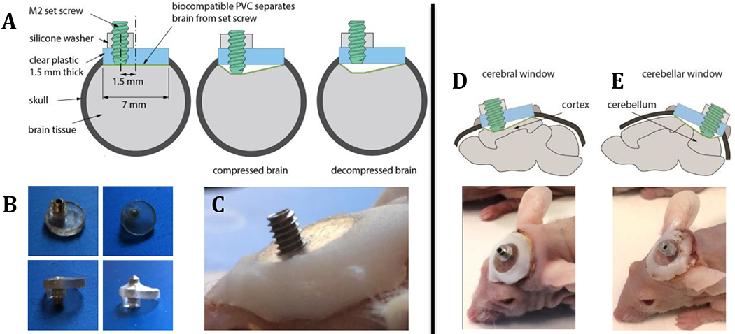
(A) The model system is comprised of a set screw mounted on a transparent cranial window to simulate the chronic application of compressive stress on the normal brain. The model also recapitulates mechanical stress relaxation after tumor removal by unloading the compression from the set screw (decompressing). (B) Images of cCW with biocompatible PVC and silicone washer at the compressed and uncompressed states. (C) Image of the implanted compression window. (D) cCW implanted as a cerebral window to apply chronic compression on cortex. (E) cCW implanted as cerebellar window to apply chronic compression on cerebellum.
Figure 3 – Compression cranial window (cCW) recapitulates the compressed brain tissue by brain tumors.

(A) The brain surrounding the nodular tumor is compressed as evident by the deformed nuclei of neurons (NeuN stain). (B) Morphologically-similar compression of the neurons can be observed when the brain is compressed via cCW. Scale bar = 50 μm.
Early applications in cancer models.
In our initial studies, we demonstrated for the first time that solid stress is causally linked to vascular and neurological dysfunction in the brain, by applying and then removing chronic cerebral compression to mimic the mechanics of tumor growth and surgical resection. Furthermore, we were able to utilize this cCW to screen for effective therapeutic interventions capable of reducing solid stress-induced neuronal death and improving neurological function, assessed via motor coordination and neuronal survival in mice. Thus, we were able to identify lithium as an efficient agent that can protect against solid stress effects, which may prove useful to enhance treatment efficacy in combination with anti-cancer agents for brain tumor patients in future clinical trials [15].
Potential applications in other disease models.
Beyond the study of malignant primary and secondary brain tumors, this modified cCW could be utilized in preclinical models of other diseases that present with solid masses in the brain. Some examples are: 1) “tumor-like” infectious lesions (including cysts or abscesses); 2) benign masses (e.g., those resulting from abnormal neurogenesis, neurofibromatosis types I and II, tuberous sclerosis, and von Hippel-Lindau syndrome); 3) tumefactive multiple sclerosis (MS) plaques; and 4) extreme vascular malformations [28, 29]. In theory, acute traumatic brain injury could even be modeled with slight modification of the cCW, i.e., by replacing the screw with a pin that freely slides in the hole allowing high-speed reversible compression to be applied. Causal studies enabled by this method in these systems could elucidate the role of mechanics in other brain disease progression [23] and reveal novel targets for treatment.
Comparison to other methods of application of mechanical forces in the brain.
In vitro assays, such as cell culture models, have been extensively used to study the causal role of compressive [30], tensile and shear stresses [31, 32] on neuronal activity and damage. These in vitro systems allow for controlled application of mechanical stress and longitudinal high-resolution imaging. However, these models suffer from a lack of the cellular diversity and interactions in the brain and the three-dimensional architecture of the microenvironment, which play an important role in transmission of mechanical stress. These models have been improved by using three-dimensional hydrogel-based systems to mimic the in vivo tissue architecture [32, 33], and organotypic culture systems [34, 35] to include the cellular diversity and cell-cell interactions; however these models still suffer from lack of blood perfusion, a critical element for studies that involve oxygenation, nutrient and drug delivery, and inflammation and immune response as well as are usually characterized by short-term experiments. The limitations of these systems necessitate complementary in vivo models to take into account the full consideration of the physical, biological, and immunological brain microenvironment in response to compressive mechanical stresses.
Previous models of brain compression in vivo have been largely based on acute expansion of an epidural balloon [36–38]. These models have been used to study ischemia, hemorrhagic stroke, traumatic brain injury, and other conditions that may affect autoregulation of cerebral blood flow, and have been used to measure intracranial pressure, arteriovenous oxygen concentrations, cerebral blood flow and oxygenation, and blood-brain barrier integrity [36–39]. Some studies have even explored the effects of controlled and isotropic epidural balloon expansion on the elastic properties of the brain tissue, including compaction and stiffening of the compressed site [40–42]. A major limitation of these systems is the lack of compatibility with high-resolution intravital microscopy to monitor the consequences of the mechanical compression longitudinally via optical imaging. One of the advantages of our model system is that it allows for longitudinal intravital microscopy during the compression or decompression stages. Another key advantage is the ability for simple and controlled application and removal of the mechanical displacement in both magnitude and rate. These are discussed in the section entitled “Advantages”.
Level of expertise needed to implement the protocol
This protocol is designed for laboratories with 1) well-established preclinical brain disease models, and 2) access to and experience with intravital imaging equipment. The main requirement for successfully implementing this protocol is the expertise and skills in small animal surgery needed for cCW implantation.
Advantages
This protocol allows for unprecedented investigation of the causal effects of tumor-generated mechanical forces on the surrounding brain tissue, coupled to dynamic intravital imaging. Laboratories that are equipped with or have access to these types of imaging platforms will be able to easily implement these methods (described in detail under “Experimental design”). The screw dimensions and window thickness can be readily tailored for the application/disease model of interest, and the inclusion of the biocompatible membrane that isolates the screw from the cortex ensures that the metal does not come into direct contact with brain cells, and the cerebrospinal fluid does not leak. Furthermore, in our initial studies [15]and with the dimensions reported here (Fig. 2), the cCW does not interfere with normal cage behavior; thus, behavioral tests can be performed as well without confounding factors. If utilizing this cCW in combination with an orthotopic tumor model, the healing process in the mice is rapid; we recommend that the cCW be implanted 10-14 days prior to tumor implantation. The methods described here for cCW implantation over the forebrain can be adapted to studies of the hindbrain (e.g., for models of medulloblastoma) utilizing established cerebellar window techniques [43, 44]. Finally, as demonstrated in our early findings [15], the cCW model can be used as a drug-screening platform for agents that can protect against the adverse effects of mechanical forces in the brain.
Limitations
The main potential limitation would be the requirement for relatively advanced expertise in animal surgery for implantation of the cCW. It is recommended to house mice bearing cCW in isolation, to prevent potential damage to the window by cagemates, which could increase associated housing costs. If a pediatric mouse model is required (e.g., medulloblastoma), researchers may encounter issues when implanting the cCW in mice that are younger than 4 weeks of age due to continued skull growth over aging [43, 44]. Thus, it is recommended to implant the cCW on mice that are at least 4 weeks old. Additionally, although intravital imaging can be utilized for the surrounding tissue, the screw obstructs visualization of the tissue immediately below the compression site.
There are several confounding factors influencing biological readouts that cannot be resolved by mechanistic utilization of this compression device. First, the forces generated by tumor growth can be exerted in all directions both intra- and extratumorally, whereas the cCW exerts force only in the direction in which the set screw is lowered from the surface of the brain. Although the growth-induced compressive forces that tumors exert on their surrounding brain can be reasonably modeled via cCW, the advancement of the screw also exerts shear stresses on the brain. However, we minimized the shear stress components at the interface of the cCW and the brain by incorporating a PVC membrane with a low friction coefficient to separate the device from the tissue. Second, because solid stress compresses blood vessels, the effects of mechanics versus hypoxia may not be able to be decoupled. For example, if neuronal damage is observed, it may be due directly to the compression or in part due to ischemic injury from compromised blood flow from compressed vessels. Third, blood vessel compression can also lead to increased interstitial fluid pressure; thus, it can be difficult to distinguish whether fluid or solid components are responsible for any downstream mechanical effects.
Experimental design
We describe here a protocol to fabricating (Fig. 4) and implementing (Fig. 5 and 6) a compressive cranial window approach for mechanistic studies of solid mechanical forces in the brain coupled to intravital imaging techniques (Fig. 7). The transparent window allows for real-time visualization of brain tissue components (e.g., neurons and blood vessels) that may be adversely affected by solid stress, which can be applied acutely or chronically (up to weeks or months) in a controlled manner. Behavioral tests can be employed without interference from the cCW, and histological and molecular evaluation of compressed brain tissues can be carried out subsequently using standardized techniques. The cCW implantation can be accomplished in under one hour with adequate surgical expertise.
Figure 4 – Procedure for fabrication of cCW.

(A) 2mm thick polyethylene plate. (B) Circular coverslips with 0.8mm diameter holes are cut from the polyethylene plate with a laser cutter. (C) The coverslip is secured with a drill press vise. The pre-cut hole in the coverslip is aligned with the drill bit on the drill press. (D) The hole made by the laser cutter is enlarged to 1.55mm in diameter. (E) Using an M2 hand tap, screw threads are created in the hole on the coverslip. (F) Close-up of the screw threads created in the 1.55mm diameter hole. (G) A 10 mm disc is punched from a PVC sheet using a 10mm biopsy punch. (H) The 10mm disc next to the PVC sheet. (I) A 7mm biopsy punch is used to create a hole in the 2mm thick silicone sheet. (J) The PVC membrane is centered on top of the 7mm hole in the silicone sheet. (K) Cyanoacrylate (“super”) glue is carefully spread along the edge of the coverslip. (L) The coverslip with wet glue is centered on top of the PVC membrane. (M) The coverslip is pushed onto the PVC membrane into the hole in the silicone sheet. (N) Make silicone washers by first punching a 1.5mm hole in the 2mm thick silicone sheet. (O) A 3mm punch is used to cut a disk concentric with the 1.5mm hole, create a donut-shaped silicone washer. (P) The resulting silicone washer. (Q) Center the silicone washer with the hole in the coverslip, opposite the side of the PVC membrane. (R) Screw an M2 screw into the coverslip from the side of the silicone washer until the tip of the screw touches the PVC membrane. (S) Side-view of the finished cCW. (T) Angled top-view of the finished cCW.
Figure 5 – Surgical procedure of implanting cCW.

(A) Skin is removed to expose the skull. (B) The connective tissues are cleaned via a cotton swab. (C) A circular groove is made in the skull via a handheld bone drill and fine burr tip. (D) After washing the debris, the groove is deepened until the disk of bone is fully released. (E) The bone and dura membrane are removed gently to avoid hemorrhage at the brain cortex. (F) The bone residue is removed carefully to avoid regrowth. (G) The brain is washed multiple times with saline. (H) cCW is placed at the desired anatomical location. (I) Saline is injected beneath the window to stop diffusion of the glue beneath the window. (J) Glue, premade in a petri dish, is applied in between the window and the surrounding skull bone. (K) The skin is brought in contact with the glue. (L) The mouse is brought back to the cage after the glue cures (<10 minutes).
Figure 6 – Timing and experimental design of cCW.

(A) The compressed brain is visualized by OCT imaging on day 0, 4, 7 and 10. (B) A sample timing of the compression associated to the growth rate of a mouse model of glioblastoma (U87). (C) A sample experimental design for chronic compression of the brain, and follow-up biological and physiological readouts.
Figure 7 – The cCW allows for intravital imaging.

Setup and sample images via (A) high resolution stereo microscopy and (B) optical coherence tomography (OCT) before and after decompression of the brain by reversing the set screw. Intravital microscopy allows us to follow the same anatomical structures over the time; white arrows indicate blood vessels undergo perfusion changes before and after decompression. Scale bars, 1 mm.
Surgery and follow-up care.
This protocol, as with standard cranial window implantations, allows for the portion of the skull to be removed and coverslip to be placed in a single surgical procedure (Fig. 5). Although we have not observed significant glial activation post window implantation in previous studies [43], it is recommended to wait 10-14 days for the potential inflammatory response to surgery to subside prior to compression and imaging. If it is desired to implant tumor cells, this can be done in a second surgical procedure after this period. Unless required for the disease model of interest, it is recommended to remove the dura mater during the implantation procedure, so as not to compromise the optical quality over time. Longitudinal imaging should be able to be performed for several months before skull regrowth occurs.
Application of compression and decompression.
The magnitude and rate of compression can be modified to recapitulate the tumor growth of interest. Fig. 6 shows an example loading profile that recapitulates the growth of a mouse model of glioblastoma. The displaced brain volume, V, can be estimated for general cCW dimensions from the following equation based on the conical section imposed by the PVC membrane:
where h is the distance the screw has traveled below the window (one full turn advances lowers the screw by one pitch size, here 0.4 mm for an M2 screw), R1 is the radius of the screw (here, R1=1 mm), and R2 is the radius of the cranial window (here, R2 = 3.5 mm), and π ≈ 3.14.
Intravital imaging modalities.
The window and set screw material are chosen based on the desired imaging modality (Table 2) such as MRI, multiphoton laser-scanning microscopy (MPLSM), and optical coherence tomography (OCT) (Fig. 7). For example, magnetic resonance imaging (MRI) can be used for a variety of techniques (e.g., perfusion, tractography, elastography [46–48]). MPLSM is highly desirable for the visualization of cellular structures (including vascular), especially when imaging stromal components in fluorescent reporter mouse models or via second harmonic generation, as well as when utilizing fluorescently-labeled injected cells, drugs, or tracers [49–51]. For mechanistic insight of vascular perfusion and blood flow rates, Doppler OCT offers a robust and rapid modality with resolution at the microvascular scale [52–54].
Table 2.
Summary of intravital imaging techniques that can be coupled to utilization of the cCW.
| Imaging Modality | Window Material | Set Screw Material | Readouts |
|---|---|---|---|
| Magnetic resonance imaging (MRI) | Plastic | Plastic | Compression (set-screw) volume Tumor volume (or other disease mass) Edema/Water Content Blood flow/perfusion Tractography Elastography |
| Multiphoton laser-scanning microscopy (MPLSM) | Glass | Metal | Blood flow/perfusion Fluorescent reporters (reporter mice; labeled cells, drugs, or tracers) |
| Optical coherence tomography (OCT) | Glass | Metal | Compression (set-screw) volume Tumor volume (or other disease mass) Blood flow/perfusion |
| 18F-FDG-PET/CT | Plastic | Plastic | Compression (set-screw) volume Tumor volume (or other disease mass) Glucose uptake |
Solid stress measurements.
We have quantified solid stress in brain tumors both intratumorally and extratumorally in the surrounding normal brain [5, 16]. However, these methods have not yet been utilized in the tissue surrounding the set screw in mouse brains bearing the cCW. Using our recently developed techniques [5, 9] – specifically, the needle-biopsy method – it is possible to measure the magnitude of solid stress (and the associated stored elastic energy) in the surrounding tissue. The required methodologies are described in detail in [9].
MATERIALS
Reagents
Mice: models as appropriate for clinically relevant investigations of human disease/disorders. ! CAUTION All animal studies must be reviewed and approved by the relevant institutional animal care and use committees and conform to all relevant ethics regulations. Animal procedures in this work were carried out following the Public Health Service Policy on Humane Care of Laboratory Animals and approved by the Institutional Animal Care and Use Committee of Massachusetts General Hospital. ◆CRITICAL For experiments meant to recapitulate pediatric disease (e.g., medulloblastoma), we recommend using mice aged 4-6 weeks old so that they are still juveniles, but not so young that rapid skull growth interferes with the cCW.
PBS (1X CellGro, 20-031-CV)
- Anesthesia:
- Ketamine (Ketaset, 100 mg/mL, Patterson Veterinary 07-803-6637 or similar)
- Xyalzine (Anased, 100 mg/mL, Patterson Veterinary 07-808-1039 or similar).
- Sterile saline (Hospira Sodium Chloride 0.9%, bacteriostatic, 30mL or similar)
- Analgesia:
- Buprenorphine (Buprenex, 0.3mg/ml, Patterson Veterinary 07-850- 2280) is used at a concentration of 0.1 mg/kg. ◆CRITICAL Buprenorphine is to be injected subcutaneously.
- Carprofen (Rimadyl, 50 mg/kl, Patterson Veterinary 07-844-7425) is used at a concentration of 5 mg/kg. ◆CRITICAL Carprofen is to be injected subcutaneously.
- Saline, for irrigation (0.9%, Owens-Minor 0706-2F7123 or similar)
Equipment
Stereotactic frame (Harvard Apparatus 75-1808 or similar)
Brightfield stereo microscope (Olympus SZ61 or similar)
Thermal pad (SHOR-LINE model 712.0000.04 or similar)
High-speed bone micro-drill, for brain surgery (Harvard Apparatus PY272-4950 or similar)
1.4 mm diameter burr tip for micro-drill (Fine Science Tools 19007-14)
Ophthalmic lubricant (Puralube IS4398 or similar)
- Coverslips, 7 mm diameter, 2 mm thick (custom cut in-house):
- Glass (Fisher 7-CIR-1-Fisher or similar)
- Polyethylene (Ted Pella #2225 or similar)
Stainless steel set screw (McMaster-Carr 92605A047, M2 × 5 mm, or similar)
Plastic (nylon) screw (McMaster-Carr 92492A703, or similar)
Allen screwdriver for M2 set screw (McMaster-Carr 6958A22)
Philips screwdriver number 0 for plastic screw (McMaster-Carr 5682A91, or similar)
Drill bit 1/16 inch (McMaster 2901A111)
M2 tap (McMaster-Carr 8305A77)
Tap Wrench (McMaster-Carr 246A23)
Polyvinyl chloride (PVC) membrane (McMaster-Carr 8562K11), 0.1 mm thick, 10 mm in diameter
Silicone disk (McMaster-Carr 2183T3), 1/16 inch thick, 3 mm diameter
Disposal biopsy punch, 1.5 mm (33-31A), 3 mm (33-32), 6 mm (33-36) and 10 mm (33-38) in diameter (Integra-Miltex or similar)
Syringe for anesthesia, 1 mL (e.g., BD, 309659 or similar)
Sterile Petri dishes (Falcon, various sizes)
Sterile gauze (Curity 6939, or similar)
Sterile cotton tip applicators, Owens and Minor WOD1002 or similar
Sterile Gelfoam, Hemostatic size 100, McKesson 189842
Sponges, 3”x3”, Cardinal Health 3307394
Cyanoacrylate (“super”) glue, all-purpose, one-drop applicator or similar
Extra fine acrylic powder, dental or nail grade (Keystone Industries 166264, or similar)
Straight iris scissors, Bonn, RS-5840 or similar
Vannas spring scissors, Bonn, RS-5611 or similar
Straight forceps, Bonn, RS-8140
Dumont forceps #3, Bonn, RS-5042
Dumont forceps #5, Bonn, RS-5045
Laser cutter, Epilog Legend Series – Mini 18
Standard Drill Press
Reagent setup
Ketamine-Xylazine mixture solution –
This 10:1 ratio anesthesia cocktail is made by adding 3 ml of Ketamine (Ketaset, 100 mg/ml), diluted 10 times, and 0.3 ml of Xylazine (Anased, 100 mg/ml), diluted 100 times, to 27 ml of sterile saline (PBS) using aseptic techniques. The mixture can be stored at room temperature (25° C) for 7 days or at 4° C for 30 days. ◆CRITICAL Administration is carried out via intraperitoneal (i.p.) injection at a dose of 1 ml per 100 g body weight.
Equipment setup
cCW fabrication –
The coverslip must be cut from a 2 mm thick polyethylene plate (Fig. 4A) as 7 mm disc with a 0.5 mm diameter hole 2 mm away from the edge, i.e. 1.5 mm from the center (Fig. 4B). The coverslip can be cut using a laser cutter with settings of 20%/100%/5000Hz (speed/power/frequency). The tolerance of the laser cutter is approximately 0.3mm at the above setting. The outer diameter of the coverslip should be 7 ± 0.3 mm. The diameter of the hole can also have a tolerance of 0.3 mm. We recommend that users perform a few trials with their available laser cutter to find specific settings that reproduce these tolerances with their equipment. The coverslip can be secured with a drill press vice and the 1.0 mm diameter hole is enlarged using a drill press with a 1.55 mm diameter drill bit (Fig. 4C and D). The drill speed can be set at 500 rpm. Due to the small diameter of drill bit, the heating will be minimal. Use an M2 tap to create screw threads in the 1.55mm diameter hole in the coverslip (Fig. 4E and F).
The coverslip is now ready to be attached to the polyvinyl chloride (PVC) membrane. The PVC membrane separates the brain tissue from the screw and coverslip. A 10 mm disk can be made out of the PVC sheet using a 10-mm punch (Fig. 4G and H). Make a hole in a 3 cm x 3 cm, 2 mm thick silicone sheet using the 7 mm punch (Fig. 4I). The hole left in this silicone membrane will be used as a template for attachment of the PVC membrane to the coverslip (Fig. 4J). Apply cyanoacrylate (“super”) glue on the edge of the coverslip (without the screw attached; Fig. 4K). Make sure the glue covers the side edge but does not spread to the flat surfaces of the coverslip. You can spread a thin layer of glue on a petri dish, and roll the edge of the coverslip through the glue for a consistent and even application. Once the glue is applied on the edge of the coverslip, place a PVC membrane disk centered on top of the 7 mm hole left in the silicone sheet. Place the coverslip centered on top of the membrane (Fig. 4L). Push the coverslip so both the coverslip and the PVC membrane below it are squeezed into the 7 mm hole in the silicone sheet (Fig. 4M). In this process, the extra PVC will fold on the edge of the coverslip where the glue has been applied, and ensure that equal pressure is applied on the membrane for consistent attachment.
Make silicone washers by first punching a 1.5 mm hole in the 2 mm thick silicone sheet (Fig. 4N). Next, use the 3 mm punch to cut a disk centered on the first 1.5 mm hole (Fig. 4O). This results in a donut shaped silicone washer (Fig. 4P). This silicone washer ensures that the screw is secured in place in the coverslip with minimal recoil and to prevent unintended turning. Center the silicone washer around the threaded hole in the coverslip on the face opposite the PVC membrane (Fig. 4Q). Screw an M2 screw in the coverslip until it touches the PVC membrane on the other side (Fig. 4S and T).
PROCEDURE
Surgery – TIMING: 45 minutes
(See Fig. 5 for images of sequential surgical steps.)
Administer carprofen at a dose of 5 mg/kg body weight subcutaneously 30 minutes prior to surgery. Anesthetize the mouse with 1 ml per 100 g body weight (i.p.) of the ketamine and xylazine cocktail. Test that the mouse is fully anesthetized via pedal reflex and respiration monitoring. ! CAUTION All experiments with mice must be performed under institutional and national regulations and guidelines.
Apply ophthalmic lubricant on the eyes once the mouse is fully anesthetized.
Using the straight iris scissors, remove a 10 mm circular area of skin and connective tissue from the skull. Expose and clean the connective tissue and skull with a sterile cotton swab and rinse with sterile saline. ◆CRITICAL The location of this tissue removal must be made above the anatomical location of interest as dictated by the use of clinically relevant mouse models. ! CAUTION Bleeding may occur. TROUBLESHOOTING
Place the mouse in the chosen stereotactic frame and position the head under the stereomicroscope. ◆CRITICAL Ensure that the mouse is stably secured and correctly positioned. The following steps will be performed under the stereomicroscope.
Mark a 6 mm circle over the exposed region of interest of the skull with a pen.
Equipped with a 1.4 mm diameter burr tip, use the micro-drill to make a groove at the border of the marked circle. ◆CRITICAL Proceed with this drilling step slowly to avoid damage, and regularly rinse the area with cold saline to avoid thermally-induced injury to the brain or surrounding skull. TROUBLESHOOTING
Over subsequent repetitive drilling, gradually increase the depth of the groove until the circular disk of bone becomes loose, or the surface of the brain tissue becomes visible. ◆CRITICAL Be sure not to apply excessive pressure to avoid damage to the brain. Maintain constant drill motion to avoid heating damage to the brain or surrounding skull. ! CAUTION Bleeding may occur. TROUBLESHOOTING
Using the #3 Dumont forceps, carefully separate the circular bone disk from the dura mater underneath. ◆CRITICAL Proceed with this step very slowly so as not to damage the brain surface vasculature and rinse with sterile saline during bone flap removal. ! CAUTION The dura mater may tear, resulting in bleeding. TROUBLESHOOTING
Once the bone flap is removed, place a piece of gelfoam soaked in 0.9% sterile saline on the dura mater and apply sterile saline to the exposure site as necessary to keep the tissue hydrated. Using the #3 Dumont forceps, remove any remaining pieces of the bone from the edge of the circular disk.
OPTIONAL If it is desired to remove the dura mater, move the gelfoam to the edge of the craniectomy to absorb saline or blood during this step. Using the Dumont #5 forceps, create a small opening to the dura mater close to the edge of the disk. Insert the Vannas microscissors into the opening and cut the dura and the arachnoid membranes from the surface of the brain. Once removed, rinse the surface of the brain with sterile saline. ◆CRITICAL Remove the dura slowly and carefully from the bone edge, avoiding pulling the dura or applying pressure to the brain below, while making sure to avoid damage to large blood vessels. ! CAUTION Bleeding may occur. TROUBLESHOOTING
Place the fabricated cCW over the surface of the exposed brain region, using saline to keep the tissue surface wet. ◆CRITICAL The surrounding bone should remain dry for the next step. ◆CRITICAL Be sure to use cCWs fabricated with coverslips of the appropriate material for the required subsequent imaging modalities (glass or plastic). ! CAUTION Avoid placing the screw over the sagittal sinus.
Affix the cCW to the bone using a 1:1 mixture of histocompatible cyanoacrylate glue and fine acrylic powder, making sure to apply the mixture quickly before it sets. ◆CRITICAL The surrounding bone must be dry in order to ensure proper fixation of the cCW to the glue. Do not allow the glue to contact the brain tissue directly. TROUBLESHOOTING
Post-surgery, monitor the mouse on the heading pad until the anesthesia wears off. Once awake, administer buprenorphine subcutaneously at a dose of 0.1 mg/kg body weight. ◆CRITICAL Be sure to place only one mouse per cage to reduce the chance of damage to the cCW by cagemates. TROUBLESHOOTING
Administer carprofen at a dose of 5 mg/kg body weight subcutaneously for pain management over the next 1-2 days, or as needed.
Applying Compression and Decompression – TIMING: 5 minutes
(See Fig. 6 for examples of compression profiles. See Table 1 for the amount of rotation required for a desired volume displacement, estimated based on the thread size.)
Table 1.
Rotation angles/turns and their associated depth and displaced brain tissue volume for a cCW with M2 set screw.
| Rotation | Depth, h (mm) | Displaced brain volume, V (mm3) |
|---|---|---|
| 90° | 0.1 | 1.75 |
| 180° | 0.2 | 3.5 |
| 360° (1 turn) | 0.4 | 7.0 |
| 2 turns | 0.8 | 14.0 |
| 3 turns | 1.2 | 21.0 |
15. Anesthetize the mouse with 1 ml per 100 g body weight of the ketamine and xylazine cocktail. Test that the mouse is fully anesthetized via pedal reflex and respiration monitoring. ! CAUTION All experiments with mice must be performed under institutional and national regulations and guidelines.
16. Apply the compression by turning the screw clockwise. The compression level and frequency of compression depends on the study of interest. As an example, to simulate the chronic compression due to tumor growth [15], we applied 1.3 mm3/day (volume of compression from the screw) for two weeks.
17. OPTIONAL Imaging methods such as OCT can be used to verify the compression level by locating the bottom surface of the screw with respect to the top surface of the brain cortex. During this step the compression can be adjusted in case of recoil or if the screw becomes unscrewed due to mouse movement and/or intracranial pressure. TROUBLESHOOTING
18. OPTIONAL To simulate the tumor removal, decompress the brain cortex by unscrewing the screw. The screw should be left at the coverslip (zero) level.
Imaging – TIMING: Variable
(See Fig. 7 for images of compression via OCT imaging.)
19. OPTIONAL As described under “Experimental Design”, the transparent cCW is ideal for intravital imaging of brain structures during solid mechanical force application. Depending on the imaging modality (e.g., OCT), the entire brain can be imaged on the order of minutes, but longer imaging studies may be desired. ! CAUTION This optional step, as with all experiments with mice, must be performed under institutional and national regulations and guidelines.
Treatment - TIMING: Variable
20. OPTIONAL Treat the cCW bearing-mice as with any other mice with standard cranial window, and with more caution when holding the mice. The thick coverslip is more prone to detachment from the skull compared to a standard cranial window, and so the mouse should be handled with care. TROUBLESHOOTING
Tissue Collection – TIMING: 5 minutes
21. OPTIONAL If desired to perform histological analyses on tissues collected at the end of the mechanical compression studies, we recommend performing whole animal perfusion fixation in order to preserve the deformed geometric and architectural features of the brain tissue under compression. The entire mouse head can be harvested after intracardiac perfusion with 2% formaldehyde in PBS and then fixed with 2% formaldehyde in PBS for 24-72 hours. Then the brains can be dissected from the head and embedded in paraffin. ! CAUTION This optional step, as with all experiments with mice, must be performed under institutional and national regulations and guidelines. ! CAUTION Formaldehyde is toxic and must be handled carefully under a chemical fume hood. Alternatively, brain tissue can be collected for molecular analyses (e.g., DNA, RNA, protein) using standard collection methods.
TIMING
On a per mouse basis:
Surgery (Steps 1-14): 45 minutes
Applying Compression (and Decompression; optional) (Steps 15-18): 5 minutes
Imaging (Optional; Step 19): Variable
Treatment (Optional; Step 20): Variable
Tissue Collection (Optional; Step 21): 5 minutes
TROUBLESHOOTING
See Table 5 for troubleshooting guidance.
Table 5.
Troubleshooting.
| Step | Problem | Possible Reason | Solution |
|---|---|---|---|
| 3, 7, 8, 10 | Bleeding from skull during surgery | Damage to blood vessels | Bleeding can be controlled with gelfoam and cotton swabs, and rinsing with sterile saline. If bleeding persists at the cCW surface post-surgery, it is recommended to exclude this mouse from the study if the bleeding or clotting interferes with the imaging modality. |
| 6 | Poor drilling and/or excessive heating of bone and tissue | Drill bit has become dull | The drill bits will wear down eventually and should be discarded and replaced after 100 cCW implantations. Drill bits should also be dry-heat sterilized. |
| 6 | Drill breaches skull and penetrates underlying tissue | Excess force and/or speed during drilling | Exclude mouse from experiment; proceed with slower and less forceful drilling on remaining mice in study. |
| 10, 19 | Poor imaging quality | Dura mater intact | Unless required for the disease model of interest, it is recommended to remove the dura mater during the surgical cCW implantation procedure, so as not to compromise optical quality over time. |
| 12 | Glue directly contacts the brain | Insufficient layer of saline on tissue below cCW | Saline should be applied on the exposed surface of the brain under the cCW and to the edge of the coverslip to exclude any glue that may penetrate into the exposed tissue area. Be sure to apply sufficient amounts of saline and apply the glue to the surrounding (dry) bone carefully. |
| 11, 12 | cCW becomes loose or dislodged | Bone is wet during application of glue | Be sure to thoroughly dry the bone surrounding the window site prior to adding the glue with a cotton applicator. Then add saline carefully one drop at a time to cover the surface of the brain just to the edge of the area that the window will cover. |
| 13, 20 | cCW becomes loose or dislodged | Disruption/damage of cCW by cagemates | It is highly recommended to house mice individually. Researchers should account for a 5% failure rate based on cCW disruption either by mouse activity or operator error. |
| Post-surgery | Regrowth of skull bone over cCW site | Insufficient removal of bone during implantation surgery | If compression has not yet been initiated, the cCW can be removed, the bony regrowth removed, and a new cCW implanted. However, if mechanical force studies have begun, it is recommended to exclude this mouse from the study if interfering with compression or imaging. |
| Post-surgery | cCW becomes loose or is lost | Dislodged from mouse handling | It is highly recommended that the mouse is handled gently, and held from areas around the shoulder rather than neck so as not to disrupt the cCW. |
| Post-surgery (e.g., Step 17) | Lost or loose screw | The silicone washer is not in contact with coverslip | Prior to implanting cCW the silicone washer needs to be push toward the coverslip to make full contact to avoid a loose screw. |
ANTICIPATED RESULTS
One of the greatest advantages of the cCW is its ability to be coupled to intravital imaging (as described in the Introduction and summarized in Table 2). We have implemented such modalities as standard stereo microscope imaging and OCT (Fig. 7). For example, via OCT imaging of perfused vessels we found in our previous study that compression of the cortex with cCW compressed not only the tissue immediately below the screw, but also reduced the vascular perfusion in the concentric surrounding tissue. Subsequent decompression of the cortex (simulating brain tumor resection) restored vessel perfusion [15]
Importantly, as described in Step 21, it is possible to perform histological and molecular analyses and transciptomics on the brain tissues collected at the end of the mechanical compression studies (Fig. 8). This allows for characterization of brain molecular and cellular structure, as well as neurological function responses to mechanical compression. Potential histological markers of interest are summarized in Table 3. Through histology we have been able to compare the extent and effect of compression with the cCW to that of a brain tumor (Fig. 1), and with the appropriate immunostaining we have been able to study neurons, astrocytes, perfused vessels, and markers of cell death and autophagy (Fig. 8). Utilizing quantitative image analysis, we previously showed that compression reduces neurons in the cortex, while decompression partially restores a higher number of neuronal cells. Microanatomy can also be analyzed via electron microscopy after compression, e.g., to assess condensed chromatin in apoptotic/necrotic neurons (Fig. 8D) [15].
Figure 8 – Chronic compression results in cellular biological responses that can be quantified via histological and molecular techniques.
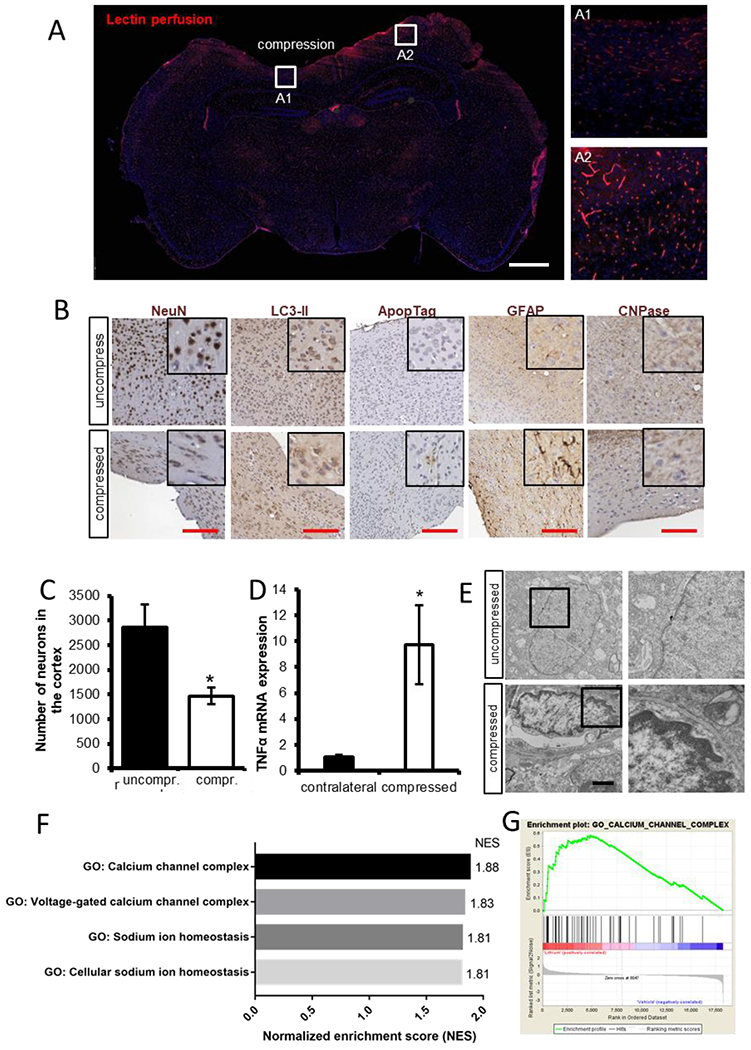
(A) Lectin perfusion (red) shows perfused vessels that are lowered in compressed area A1 compared to the uncompressed area A2 (blue nuclear stain – DAPI). Scale bar, 1 mm. (B) Examples of IHC staining of neuronal nuclei (NeuN), autophagy (LC3-II), apoptosis (ApopTag), activated astrocytes (GFAP), and oligodendrocytes (CNPase). Scale bar, 100 μm. (C) Neuronal loss can be quantified from immunohistochemical (IHC) analysis. (D) Gene expression of TNFa (via qRT-PCR) has been shown to increase in response to compression. (E) Chromatin condensation as a result of compression can be quantified via electron microscopy. Scale bar, 1 μm. (F) An example of enrichment plot of gene ontology after RNA sequencing of brain tissue under chronic compression with and without treatment with lithium, a neuroprotective agent. The gene ontologies associated with calcium channel complex and sodium ion homeostasis were significantly upregulated in lithium-treated cortexes (FDR<0.25). (G) An example of gene set enrichment analysis (GSEA) calcium channel complex from GSEA for the brain under compressive stresses treated with lithium.
Table 3.
Examples of relevant markers for murine brain cell histology after acute or chronic compression with the cCW.
| Molecular/Cellular Feature | Marker |
|---|---|
| Vasculature | |
| Endothelial cells | CD31 |
| Perivascular cells | Desmin, αSMA |
| Basement membrane | Collagen IV, laminin, agrin |
| Perfusion | Lectin*, dextran* |
| Neurons | |
| Neural stem cells | ALDH, Nestin, SOX2 |
| Neural progenitors | NCAM, Musashi-1 |
| Mature neurons | NeuN, GAD |
| Glia | |
| Astrocytes | GFAP, GLAST, GLT-1 |
| Microglia | Iba1, TMEM119 |
| Oligodendrocytes | PDGFRα, NG2, Olig1-3, OSP |
| Cell Proliferation/Death | |
| Proliferation | BrdU*, Ki-67, PCNA |
| Apoptosis | Apoptag, cleaved caspase-3 |
| Autophagy | p62, Beclin-1, LC3B-II |
| Necroptosis | RIPK1, RIPK3, MLKL |
| Other Microenvironmental/Disease Factors | |
| Hypoxia | Pimonidazole*, Hif1α, |
| Plaques/tangles | Amyloid-β, tau |
| Inflammatory cytokines | IL-1β, IL-6, IL-10, TNFα |
Must be injected prior to necropsy/imaging
The effects of compression (and decompression) on mechanical properties and forces in the brain can be assessed after cCW use. For example, solid stress and elastic energy can be measured using our previously established methods [5, 9]. Edema can be measured ex vivo using established techniques such as wet/dry weight measurement, or in vivo via MRI [55]. Interstitial fluid pressure can be measured using the gold-standard wick-in-needle technique [56] through a carefully drilled hole through the coverslip adjacent to the set screw.
Mechanopathologies induced by any of the potential disease or trauma states discussed in the Introduction can promote deterioration of neurological function, motor-coordination, and behavior [57]. Thus, the cCW allows for direct study of the effect of compression on these functionalities in mice, summarized in Table 4, such as rotarod and stride length (Fig. 9). We previously found that compression results in reduced rotarod endurance and stride length in mice, whereas decompression was able to partially rescue these motor-coordination deficits [15]. Compression of different regions of the cerebral and cerebellar cortex may have differential effects on neurological functions, such as motor-coordination, balance, locomotion activity, memory, anxiety, and ataxia.
Table 4.
Potential neurological tests for mice to assess the effects of solid mechanical compression from the cCW.
| Test/Measurement | Readout |
|---|---|
| Motor Function | |
| Rotarod | Motor coordination, balance, ataxia |
| Stride length/footprint test | Balance, ataxia |
| Horizontal beam/string test | Forelimb strength and coordination |
| Elevated bridge test | Balance, ataxia |
| Nociception | |
| Hot plate/thermal probe test | Pain tolerance |
| Foot shock test | Pain tolerance |
| Tail pressure test | Pain tolerance |
| Behavior | |
| Open field test | Anxiety, habituation |
| Acoustic test | Hearing and hippocampal function |
| Morris water task | Spatial learning |
| Dark/light avoidance | Anxiety |
| Maze tests | Anxiety, spatial learning, memory |
| Object recognition | Memory |
Figure 9 – Chronic compression results in behavior responses that can be quantified via different functional tests.

While the body weight did not show a significant reduction (A), the endurance in rotarod test was significantly decreased after chronic compression (B). (C) The alteration in motor coordination was also reflected in stride length, another functional assay to test the effect of the chronic compression on brain.
Another crucial application of the cCW is its ability to be employed as a drug-screening platform to rescue the pathological effects of abnormal solid mechanics in the brain. For example, we recently utilized the cCW model to screen a number of drugs known to be neuroprotective and test whether they could revert neuronal loss due to the compression, and we found that lithium chloride alleviated the compression-mediated neuronal damage [15]. Additionally, the transparent cranial window allows for coupling to alternative treatment techniques beyond systemic therapy, such as focused ultrasound therapy [58]. Furthermore, in addition to or instead of histology, the brain tissue can be collected for molecular dissection of DNA, RNA, and protein, to assess the mechanistic effects of disease, compression/decompression, and treatment. Through bulk RNA-sequencing of compressed cortical tissue, for example, we found that lithium chloride induced upregulation of genes and pathways related to neuronal differentiation and function, and downregulation of those related to cell death [15].
In conclusion, we present here for the first time the methodologies required to establish an in vivo compression apparatus able to be coupled in real-time to dynamic intravital imaging modalities. Equipped with this simple yet effective device, scientists studying a multitude of brain diseases – from malignant tumors to traumatic brain injury – will be able to mechanistically simulate the effects of solid mechanics in their research contexts. This cCW can be used not only to understand the direct effects of mechanics on brain cells, but also to reveal new disease treatment targets and to effectively test potential protective agents.
Acknowledgements
This work was supported in part by the National Cancer Institute (P01-CA080124, R35-CA197743, U01-CA224173, and R01-CA208205 to R.K.J.; F32-CA216944 to H.T.N), the American Association of Cancer Research (19-40-50-DATT to M.D.), the Susan G. Komen Foundation (PDF14201739 to G.S.), and the European Research Council (ERC; grant agreement no. 805225 to G.S.). R.K.J.’s research is also supported by grants from the National Foundation for Cancer Research, Harvard Ludwig Center, Jane’s Trust Foundation, and the Bill and Melinda Gates Foundation.
Competing Financial Interests
R.K.J. received honorarium from Amgen, consultant fees from Enlight, Merck, Ophthotech, Pfizer, SPARC, SynDevRx, and XTuit, owns equity in Enlight, Ophthotech, and SynDevRx, and serves on the Boards of Trustees of Tekla Healthcare Investors, Tekla Life Sciences Investors, Tekla Healthcare Opportunities Fund and Tekla World Healthcare Fund. No funding or reagents from these companies were used in this study.
REFERENCES
- 1.Jain RK, Martin JD, and Stylianopoulos T, The role of mechanical forces in tumor growth and therapy. Annu Rev Biomed Eng, 2014. 16: p. 321–46. [DOI] [PMC free article] [PubMed] [Google Scholar]
- 2.Mitchell MJ, Jain RK, and Langer R, Engineering and physical sciences in oncology: challenges and opportunities. Nature Reviews Cancer, 2017. 17(11): p. 659–675. [DOI] [PMC free article] [PubMed] [Google Scholar]
- 3.Helmlinger G, et al. , Solid stress inhibits the growth of multicellular tumor spheroids. Nat Biotechnol, 1997. 15(8): p. 778–83. [DOI] [PubMed] [Google Scholar]
- 4.Stylianopoulos T, et al. , Causes, consequences, and remedies for growth-induced solid stress in murine and human tumors. Proc Natl Acad Sci U S A, 2012. 109(38): p. 15101–8. [DOI] [PMC free article] [PubMed] [Google Scholar]
- 5.Nia HT, et al. , Solid stress and elastic energy as measures of tumour mechanopathology. Nature Biomedical Engineering, 2016. 1: p. 0004. [DOI] [PMC free article] [PubMed] [Google Scholar]
- 6.Padera TP, et al. , Pathology: cancer cells compress intratumour vessels. Nature, 2004. 427(6976): p. 695. [DOI] [PubMed] [Google Scholar]
- 7.Chauhan VP, et al. , Angiotensin inhibition enhances drug delivery and potentiates chemotherapy by decompressing tumour blood vessels. Nat Commun, 2013. 4: p. 2516. [DOI] [PMC free article] [PubMed] [Google Scholar]
- 8.Chauhan VP, et al. , Compression of Pancreatic Tumor Blood Vessels by Hyaluronan Is Caused by Solid Stress and Not Interstitial Fluid Pressure. Cancer Cell, 2014. 26(1): p. 14–15. [DOI] [PMC free article] [PubMed] [Google Scholar]
- 9.Nia HT, et al. , Quantifying solid stress and elastic energy from excised or in situ tumors. Nat Protoc, 2018. 13(5): p. 1091–1105. [DOI] [PMC free article] [PubMed] [Google Scholar]
- 10.Tse JM, et al. , Mechanical compression drives cancer cells toward invasive phenotype. Proc Natl Acad Sci U S A, 2012. 109(3): p. 911–6. [DOI] [PMC free article] [PubMed] [Google Scholar]
- 11.Ricca BL, et al. , Transient external force induces phenotypic reversion of malignant epithelial structures via nitric oxide signaling. Elife, 2018. 7: p. e26161. [DOI] [PMC free article] [PubMed] [Google Scholar]
- 12.Montel F, et al. , Stress clamp experiments on multicellular tumor spheroids. Phys Rev Lett, 2011. 107(18): p. 188102. [DOI] [PubMed] [Google Scholar]
- 13.Delarue M, et al. , Compressive Stress Inhibits Proliferation in Tumor Spheroids through a Volume Limitation. Biophysical Journal, 2014. 107(8): p. 1821–1828. [DOI] [PMC free article] [PubMed] [Google Scholar]
- 14.Fernández-Sánchez ME, et al. , Mechanical induction of the tumorigenic [beta]-catenin pathway by tumour growth pressure. Nature, 2015. 523(7558): p. 92–95. [DOI] [PubMed] [Google Scholar]
- 15.Seano G, et al. , Solid stress in brain tumours causes neuronal loss and neurological dysfunction and can be reversed by lithium. Nature Biomedical Engineering, 2019. 3(3): p. 230–245. [DOI] [PMC free article] [PubMed] [Google Scholar]
- 16.Seano* G, et al. , Neurological dysfunction caused by brain tumor-generated solid stress is reversed by lithium. Accepted in Nature Biomedical Engineering. [DOI] [PMC free article] [PubMed] [Google Scholar]
- 17.Amidei C and Kushner DS, Clinical implications of motor deficits related to brain tumors. Neuro-Oncology Practice, 2015. 2(4): p. 179–184. [DOI] [PMC free article] [PubMed] [Google Scholar]
- 18.Mukand JA, et al. , Incidence of neurologic deficits and rehabilitation of patients with brain tumors. Am J Phys Med Rehabil, 2001. 80(5): p. 346–50. [DOI] [PubMed] [Google Scholar]
- 19.Kushner DS and Amidei C, Rehabilitation of motor dysfunction in primary brain tumor patients. Neuro-Oncology Practice, 2015. 2(4): p. 185–191. [DOI] [PMC free article] [PubMed] [Google Scholar]
- 20.Sawaya R, et al. , Neurosurgical outcomes in a modern series of 400 craniotomies for treatment of parenchymal tumors. Neurosurgery, 1998. 42(5): p. 1044–55; discussion 1055–6. [DOI] [PubMed] [Google Scholar]
- 21.Rees JH, Diagnosis and treatment in neuro-oncology: an oncological perspective. Br J Radiol, 2011. 84 Spec No 2(special_issue_2): p. S82–9. [DOI] [PMC free article] [PubMed] [Google Scholar]
- 22.Farago N, et al. , Human neuronal changes in brain edema and increased intracranial pressure. Acta Neuropathologica Communications, 2016. 4(1): p. 78. [DOI] [PMC free article] [PubMed] [Google Scholar]
- 23.Goriely A, et al. , Mechanics of the brain: perspectives, challenges, and opportunities. Biomech Model Mechanobiol, 2015. 14(5): p. 931–65. [DOI] [PMC free article] [PubMed] [Google Scholar]
- 24.Unterberg AW, et al. , Edema and brain trauma. Neuroscience, 2004. 129(4): p. 1021–9. [DOI] [PubMed] [Google Scholar]
- 25.de Groot J and Sontheimer H, Glutamate and the biology of gliomas. Glia, 2011. 59(8): p. 1181–9. [DOI] [PMC free article] [PubMed] [Google Scholar]
- 26.Sontheimer H, A role for glutamate in growth and invasion of primary brain tumors. J Neurochem, 2008. 105(2): p. 287–95. [DOI] [PMC free article] [PubMed] [Google Scholar]
- 27.E Savaskan N, et al. , Neurodegeneration in the brain tumor microenvironment: glutamate in the limelight. Current neuropharmacology, 2015. 13(2): p. 258–265. [DOI] [PMC free article] [PubMed] [Google Scholar]
- 28.Huisman TA, Tumor-like lesions of the brain. Cancer Imaging, 2009. 9 Spec No A(Special issue A): p. S10–3. [DOI] [PMC free article] [PubMed] [Google Scholar]
- 29.Cunliffe CH, et al. , Intracranial lesions mimicking neoplasms. Arch Pathol Lab Med, 2009. 133(1): p. 101–23. [DOI] [PubMed] [Google Scholar]
- 30.Bar-Kochba E, et al. , Strain and rate-dependent neuronal injury in a 3D in vitro compression model of traumatic brain injury. Sci Rep, 2016. 6: p. 30550. [DOI] [PMC free article] [PubMed] [Google Scholar]
- 31.Lusardi TA, et al. , Effect of acute calcium influx after mechanical stretch injury in vitro on the viability of hippocampal neurons. J Neurotrauma, 2004. 21(1): p. 61–72. [DOI] [PubMed] [Google Scholar]
- 32.Pfister BJ, et al. , An in vitro uniaxial stretch model for axonal injury. Ann Biomed Eng, 2003. 31(5): p. 589–98. [DOI] [PubMed] [Google Scholar]
- 33.Teixeira FG, et al. , Bioengineered cell culture systems of central nervous system injury and disease. Drug Discov Today, 2016. 21(9): p. 1456–1463. [DOI] [PubMed] [Google Scholar]
- 34.Schoeler M, et al. , Dexmedetomidine is neuroprotective in an in vitro model for traumatic brain injury. Bmc Neurology, 2012. 12(1): p. 20. [DOI] [PMC free article] [PubMed] [Google Scholar]
- 35.Morrison III B, et al. , An in vitro model of traumatic brain injury utilising two-dimensional stretch of organotypic hippocampal slice cultures. Journal of neuroscience methods, 2006. 150(2): p. 192–201. [DOI] [PubMed] [Google Scholar]
- 36.Xu BN, et al. , Pathophysiology of brain swelling after acute experimental brain compression and decompression. Neurosurgery, 1993. 32(2): p. 289–96; discussion 296. [DOI] [PubMed] [Google Scholar]
- 37.Miller JD, Stanek AE, and Langfitt TW, Cerebral blood flow regulation during experimental brain compression. J Neurosurg, 1973. 39(2): p. 186–96. [DOI] [PubMed] [Google Scholar]
- 38.Leech P and Miller JD, Intracranial volume–pressure relationships during experimental brain compression in primates: 1. Pressure responses to changes in ventricular volume. Journal of Neurology, Neurosurgery & Psychiatry, 1974. 37(10): p. 1093–1098. [DOI] [PMC free article] [PubMed] [Google Scholar]
- 39.De la Torre JC, et al. , Dimethyl sulfoxide in the treatment of experimental brain compression. J Neurosurg, 1973. 38(3): p. 345–54. [DOI] [PubMed] [Google Scholar]
- 40.Sullivan HG, et al. , The physiological basis of intracranial pressure change with progressive epidural brain compression. An experimental evaluation in cats. J Neurosurg, 1977. 47(4): p. 532–50. [DOI] [PubMed] [Google Scholar]
- 41.Schettini A and Walsh EK, Brain tissue elastic behavior and experimental brain compression. Am J Physiol, 1988. 255(5 Pt 2): p. R799–805. [DOI] [PubMed] [Google Scholar]
- 42.Schettini A and Walsh EK, Brain elastic behavior in experimental brain compression: influence of steroid therapy. Brain Res, 1984. 305(1): p. 141–3. [DOI] [PubMed] [Google Scholar]
- 43.Askoxylakis V, et al. , A cerebellar window for intravital imaging of normal and disease states in mice. Nat Protoc, 2017. 12(11): p. 2251–2262. [DOI] [PMC free article] [PubMed] [Google Scholar]
- 44.Snuderl M, et al. , Targeting placental growth factor/neuropilin 1 pathway inhibits growth and spread of medulloblastoma. Cell, 2013. 152(5): p. 1065–76. [DOI] [PMC free article] [PubMed] [Google Scholar]
- 45.Niermann KJ, et al. , Measuring tumor perfusion in control and treated murine tumors: correlation of microbubble contrast-enhanced sonography to dynamic contrast-enhanced magnetic resonance imaging and fluorodeoxyglucose positron emission tomography. J Ultrasound Med, 2007. 26(6): p. 749–56. [DOI] [PubMed] [Google Scholar]
- 46.Calabrese E, et al. , A Diffusion MRI Tractography Connectome of the Mouse Brain and Comparison with Neuronal Tracer Data. Cereb Cortex, 2015. 25(11): p. 4628–37. [DOI] [PMC free article] [PubMed] [Google Scholar]
- 47.Kober F, Duhamel G, and Callot V, Cerebral Perfusion MRI in Mice, in In vivo NMR Imaging. 2011, Springer. p. 117–138. [DOI] [PubMed] [Google Scholar]
- 48.Kearney SP, et al. , Simultaneous 3D MR elastography of the in vivo mouse brain. Phys Med Biol, 2017. 62(19): p. 7682–7693. [DOI] [PubMed] [Google Scholar]
- 49.Kamoun WS, et al. , Simultaneous measurement of RBC velocity, flux, hematocrit and shear rate in vascular networks. Nat Methods, 2010. 7(8): p. 655–60. [DOI] [PMC free article] [PubMed] [Google Scholar]
- 50.Fukumura D, et al. , Tumor microvasculature and microenvironment: novel insights through intravital imaging in pre‐clinical models. Microcirculation, 2010. 17(3): p. 206–225. [DOI] [PMC free article] [PubMed] [Google Scholar]
- 51.Jain RK, Munn LL, and Fukumura D, Dissecting tumour pathophysiology using intravital microscopy. Nature Reviews Cancer, 2002. 2(4): p. 266–276. [DOI] [PubMed] [Google Scholar]
- 52.Blatter C, et al. , Simultaneous measurements of lymphatic vessel contraction, flow and valve dynamics in multiple lymphangions using optical coherence tomography. Journal of biophotonics, 2017: p. e201700017. [DOI] [PMC free article] [PubMed] [Google Scholar]
- 53.Blatter C, et al. , In vivo label-free measurement of lymph flow velocity and volumetric flow rates using Doppler optical coherence tomography. Scientific Reports, 2016. 6: p. 29035. [DOI] [PMC free article] [PubMed] [Google Scholar]
- 54.Vakoc BJ, et al. , Three-dimensional microscopy of the tumor microenvironment in vivo using optical frequency domain imaging. Nature Medicine, 2009. 15(10): p. 1219–U151. [DOI] [PMC free article] [PubMed] [Google Scholar]
- 55.Kamoun WS, et al. , Edema control by cediranib, a vascular endothelial growth factor receptor–targeted kinase inhibitor, prolongs survival despite persistent brain tumor growth in mice. Journal of clinical oncology, 2009. 27(15): p. 2542. [DOI] [PMC free article] [PubMed] [Google Scholar]
- 56.Boucher Y, et al. , Interstitial fluid pressure in intracranial tumours in patients and in rodents. Br J Cancer, 1997. 75(6): p. 829–36. [DOI] [PMC free article] [PubMed] [Google Scholar]
- 57.Brooks SP, Trueman RC, and Dunnett SB, Assessment of motor coordination and balance in mice using the rotarod, elevated bridge, and footprint tests. Current protocols in mouse biology, 2012. 2(1): p. 37–53. [DOI] [PubMed] [Google Scholar]
- 58.Arvanitis CD, et al. , Mechanisms of enhanced drug delivery in brain metastases with focused ultrasound-induced blood–tumor barrier disruption. Proceedings of the National Academy of Sciences, 2018: p. 201807105. [DOI] [PMC free article] [PubMed] [Google Scholar]