Abstract
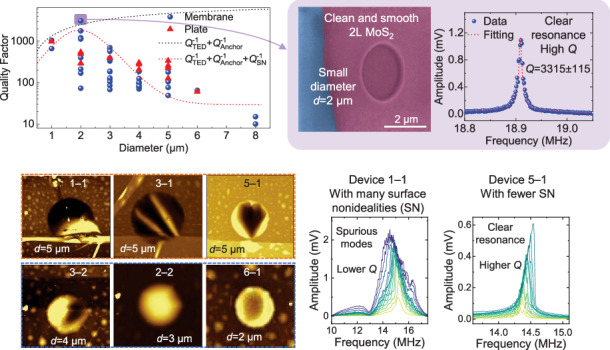
A high quality (Q) factor is essential for enhancing the performance of resonant nanoelectromechanical systems (NEMS). NEMS resonators based on two-dimensional (2D) materials such as molybdenum disulfide (MoS2) have high frequency tunability, large dynamic range, and high sensitivity, yet room-temperature Q factors are typically less than 1000. Here, we systematically investigate the effects of device size and surface nonidealities on Q factor by measuring 52 dry-transferred fully clamped circular MoS2 NEMS resonators with diameters ranging from 1 μm to 8 μm, and optimize the Q factor by combining these effects with the strain-modulated dissipation model. We find that Q factor first increases and then decreases with diameter, with an optimized room-temperature Q factor up to 3315 ± 115 for a 2-μm-diameter device. Through extensive characterization and analysis using Raman spectroscopy, atomic force microscopy, and scanning electron microscopy, we demonstrate that surface nonidealities such as wrinkles, residues, and bubbles are especially significant for decreasing Q factor, especially for larger suspended membranes, while resonators with flat and smooth surfaces typically have larger Q factors. To further optimize Q factors, we measure and model Q factor dependence on the gate voltage, showing that smaller DC and radio-frequency (RF) driving voltages always lead to a higher Q factor, consistent with the strain-modulated dissipation model. This optimization of the Q factor delineates a straightforward and promising pathway for designing high-Q 2D NEMS resonators for ultrasensitive transducers, efficient RF communications, and low-power memory and computing.
Subject terms: NEMS, Electrical and electronic engineering
Introduction
The quality (Q) factor is critical in resonant micro/nanoelectromechanical systems (MEMS/NEMS) because a higher Q factor represents lower energy dissipation, better frequency selectivity, and higher sensitivity, all of which are highly desirable for ultrasensitive resonant transducers, low-phase-noise voltage-controlled oscillators, highly selective filters, and ultralow-power memory and computing1,2. As resonators scale down to nanoscales and even atomic scales, dissipation mechanisms can become more complex, and it has been reported that the Q factor generally decreases with device volume and critical dimension3. Specifically, for doubly clamped beam resonators the Q factor increases with length but decreases with width4. In NEMS resonators, surface loss, anchor loss, frequency-independent material friction, and thermoelastic dissipation have all been considered potential dominant damping mechanisms5,6. Therefore, a deep understanding of the size effect on the Q factor and effective control of damping are increasingly important.
As resonator size continues to scale down, NEMS resonators based on two-dimensional (2D) materials, such as molybdenum disulfide (MoS2), have attracted tremendous interest because they represent the ultimate scaling in the thickness direction and have shown a number of intriguing properties7, such as a resonance frequency of up to 1.17 GHz8, an ultrawide frequency tuning range of up to 366%9, and a large dynamic range of up to 102 dB10,11. These 2D NEMS resonators have shown high potential for mass sensing with resolutions reaching ~26 yg12,13, force sensing with a sensitivity of 390 zN/Hz1/214, highly tunable voltage-controlled oscillators15,16, ultralow-power memory and computing17,18, coupling with other physical domains19–21, and quantum engineering22–24. Toward these applications and scientific explorations, a high Q factor is desirable for enhancing device performance. While the Q factor up to 1 million has been demonstrated for a graphene NEMS resonator at 15 mK25, the room-temperature Q factors for 2D NEMS resonators remain relatively lower compared with mainstream MEMS resonators, with Q factors typically in the range of a few hundred26–28 and no more than 2400 demonstrated for 2D NEMS resonators10,29,30. Strain, vibration amplitude, mode coupling, and interlayer friction have been reported to be important for their dissipation characteristics31–35. The geometric shape and critical dimension can also have important effects on the Q factor for 2D NEMS resonators. Theoretical and experimental studies have shown that 2D NEMS resonators with free edges, such as doubly clamped resonators, have larger energy dissipation and smaller Q factors than those without free edges such as fully clamped circular drumhead resonators29,36,37. Therefore, performing a comprehensive analysis of the damping mechanisms and thoroughly studying the effects of size on damping are critical for optimizing Q factors at room temperature for 2D NEMS resonators.
In this work, we systematically investigate the effect of device size on Q factors by measuring 52 MoS2 NEMS resonators with diameters varying from 1 μm to 8 μm. The results demonstrate that the Q factor first increases with diameter from 1 μm to 2 μm then decreases with diameter when larger than 2 μm. This Q vs. diameter relationship shows a different trend from previous reports on graphene NEMS resonators in which the Q factor monotonically increases with increasing diameter29. Through detailed characterization using atomic force microscopy (AFM), scanning electron microscopy (SEM), and Raman spectroscopy, we demonstrate that devices with larger diameters are more likely to include undesirable surface wrinkles, residues, and bubbles on the suspended membrane, which can lead to lower Q factors. We further find that as the diameter increases the resonance peaks do not have regular peak shapes and spurious modes emerge. By properly designing device structures as fully clamped circular membranes with 2 μm diameters and optimizing driving conditions based on the strain-modulated dissipation model, we achieve a Q factor up to 3315 ± 115 at room temperature for a bilayer MoS2 circular drumhead NEMS resonator. These results provide clear guidelines for enhancing the Q factor of 2D NEMS resonators at room temperature and pave the way for a number of applications that require high-Q NEMS resonators.
Results and discussion
We fabricate 2D NEMS resonators by first lithographically patterning substrates with surface microtrenches and contact electrodes and then transferring 2D MoS2 onto surface microtrenches using a dry-transfer process based on a polydimethylsiloxane (PDMS) stamp, which is widely used in 2D device transfer, especially for fabricating suspended devices9,20,21,31,32,34,38. All 2D MoS2 membranes are exfoliated from the same piece of bulk material; thus, we assume that minimal variations in material properties exist. The DC gate voltage VGS and radio-frequency (RF) driving voltage vRF are applied to the gate electrode through a bias tee to capacitively drive the membrane, with the contact electrode grounded. The suspended MoS2 membrane is pulled down toward the gate electrode by the electrostatic force induced by VGS, which leads to tension and resonance frequency tuning. The resonances are measured using a custom-built optical interferometry setup (Supporting Information Section S1)31,39,40. To minimize the effects of air damping and evacuate most of the air within the cavity41,42, all measurements are carried out after the 2D NEMS resonators are placed in a vacuum chamber (Fig. S1) for a minimum of 1 day. All resonance measurements are performed at a vacuum pressure of 1.2 × 10⁻² Torr at a room temperature of 300 K.
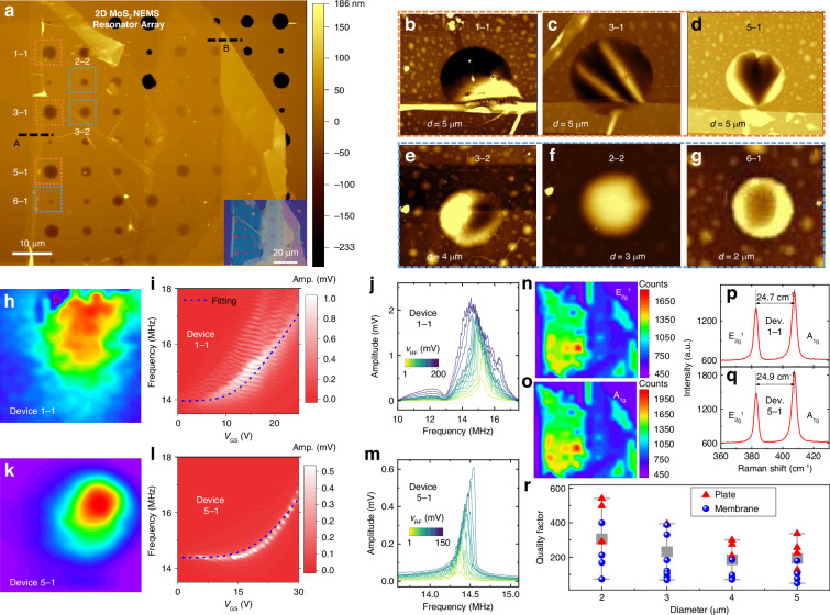
To measure the Q factors at different diameters while minimizing the effects of the variation in the MoS2 material, we fabricate an array of 2D MoS2 NEMS resonators on a substrate with 8 × 8 circular microtrenches of various diameters (Fig. 1a). The fully clamped resonator structure avoids the undesirable effects of free edges on energy dissipation and can enhance the Q factor29,36. We measure resonances from 34 resonators in the array and name each device as Device “m–n”, where m is the row number and n is the column number. The membrane surface is first characterized using AFM, showing the surface quality of the suspended membranes (Fig. 1a). Comparisons show that resonators with larger diameters (>3 μm) typically contain more wrinkles (Fig. 1b–e) on the suspended membranes than those with smaller diameters (2–3 μm) (Fig. 1f, g). We perform Raman mapping to measure the uniformity of the MoS2 material (Fig. 1n–q), where, for MoS2 with the same thickness, uniformly suspended MoS2 membranes generally show slightly higher Raman peak intensities than wrinkled membranes. The resonance spectrum for each resonator is recorded and fitted to the solution for the equation of motion to extract the Q factor (Fig. S4), with the Q factors summarized in Fig. 1r. We find that the Q factors can vary by several times for different devices with the same diameter and thickness, i.e., from 49 (Device 1–1) to 179 (Device 5–1). Furthermore, the Q factors of thicker resonators in the plate regime are typically slightly higher than those of thin resonators in the membrane regime. We then perform in-depth resonance measurements for two representative resonators (Devices 1–1 and 5–1). Mode mapping measurements are performed by fixing the laser and scanning the stage that holds the vacuum chamber with the resonator inside, demonstrating that Device 1–1, with more wrinkles on the surface (Fig. 1b), also show spurious modes (Fig. 1i–j) and a nonuniform mode shape (Fig. 1h). In contrast, Device 5–1, with a more uniform surface and fewer wrinkles (Fig. 1d), clearly shows a fundamental flexural mode shape (Fig. 1k) and regular frequency tuning characteristics (Fig. 1l). By gradually increasing the vRF, Device 5–1 exhibits linear to Duffing nonlinear resonances with hardening (Fig. 1m). The gate-tunable resonance frequency model can fit the frequency tuning characteristics of Device 5–1 well but not those of Device 1–1 because of the spurious modes (Supporting Information Section S4.1–S4.2), as follows31:
| 1 |
where R is the radius, t is the thickness, EY is the Young’s modulus, ν is the Poisson’s ratio, εr is the gate-tunable total strain, g is the initial vacuum gap, ϵ0 is the vacuum permittivity, and ρ is the mass density.
Fig. 1. Comparison of characteristics among an array of 2D MoS2 NEMS resonators with varying diameters from 2 μm to 5 μm, with either uniform or nonuniform membrane profiles.
a AFM color maps of the array of resonators. The thin region shown by the black dashed line “A” has a thickness of 5.5 nm (Fig. S2d), and the thick region shown by the black dashed line “B” has a thickness of 19 nm (Fig. S2e). Inset: optical image. The zoomed-in AFM color maps of representative resonators with diameters of (b–d) 5 μm, (e) 4 μm, (f) 3 μm, and (g) 2 μm. Resonance measurements of Device “1–1” with wrinkles on the surface and with a diameter of 5 μm, including (h) mapping of the fundamental flexural mode shape, (i) resonances at varying VGS and a fixed vRF of 10 mV with the amplitude shown in a color scale, and (j) resonances at varying vRF with a fixed VGS of 10 V. In the resonator named “m–n”, m indicates the row number and n indicates the column in the array. Measurements of Device “5–1” with fewer wrinkles on the surface and with a diameter of 5 μm, including (k) mapping of the fundamental flexural mode shape, (l) resonances at varying VGS and a fixed vRF of 10 mV, with the amplitude shown in a color scale, and (m) resonances at varying vRF with a fixed VGS of 10 V. Raman mapping of the resonator array with the color showing the Raman peak amplitude for the (n) E2g1 peak and (o) A1g peak. Raman spectra of Devices (p) 1–1 and (q) 5–1 measured near the center of the suspended membrane. r Summarized Q factors of the resonator array and modeled Q factor vs. diameter relationship, with diameters ranging from 2 μm to 5 μm. We plot the highest Q factor for each device when varying the gate voltage. The red triangles are the Q factors for devices in the plate regime (thickness >10 nm) and the blue dots are the Q factors for devices in the membrane regime (thickness ≤10 nm)
The lower Q factors for devices with more wrinkles and residues on the surface suggest the importance of surface-induced damping mechanisms in these 2D NEMS resonators. From the summarized Q vs. diameter relationship in Fig. 1r, we find that the Q factor generally decreases with increasing diameter in the range of 2 μm to 5 μm. If anchor loss or thermoelastic damping dominates, then according to previous models32,43, the Q factor should increase with increasing resonator diameter. Therefore, the results in Fig. 1r suggest that as the resonator size increases there is a higher chance that surface residues and wrinkles induce more energy loss.
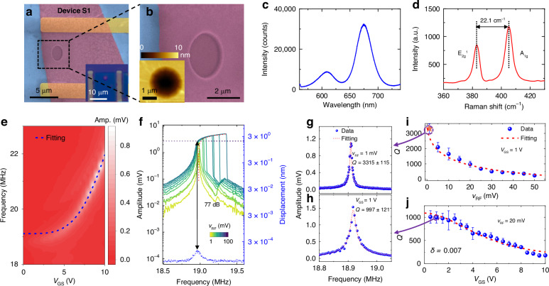
To further validate the size dependence of Q factor for thinner resonators and to achieve a high Q factor in MoS2 NEMS resonators, we fabricate another singly-isolated MoS2 NEMS resonator (Device S1) with a diameter of 2 μm and a bilayer thickness. The clean, flat, and smooth surface in the suspended region is confirmed by the SEM images (Fig. 2a, b). In addition, the bilayer thickness and high quality of the MoS2 material are confirmed by the high PL intensity and Raman peak separation of 22.1 cm−1 (Fig. 2c, d)39,44. VGS tuning of the resonance frequency shows a trend that can be well fitted by the frequency tuning model (Fig. 2e), and resonance measurements obtained by increasing the vRF clearly reveal a transition from undriven thermomechanical resonance to nonlinear driven resonances (Fig. 2f). Furthermore, the Q factor decreases with increasing VGS and vRF (Fig. 2g–j), which can be well fitted to the strain-modulated thermoelastic dissipation model (Supporting Information Section S4.3):
| 2 |
where δ is a fitting parameter representing the loss angle in the complex form of Young's modulus, and x0 is the vibration amplitude that is proportional to |VGS × vRF|. From fitting to the gate tuning of the Q factor we can extract δ for each resonator. By optimizing the diameter, minimizing surface nonidealities, and decreasing the driving strength, we achieve a high Q factor up to 3315 ± 115 at vRF = 1 mV and VGS = 1 V (Fig. 2g). This Q factor is comparable to that of several piezoelectric MEMS resonators measured under similar conditions45.
Fig. 2. Resonance characteristics for another MoS2 NEMS resonator (Device S1) with a diameter of 2 μm, which is a singly-isolated resonator with a bilayer thickness and flat, smooth suspended material.
a False-colored SEM image of the resonator. Inset: optical image. b Zoomed-in false-colored SEM image of the resonator. Inset: AFM image. c PL spectrum showing high intensity. d Raman spectrum showing the difference between the E2g1 and A1g peaks at ~22.1 cm−1, corresponding to bilayer MoS2. Measured resonances (e) at varying VGS at a fixed vRF of 20 mV, with the amplitude shown in color scale, and (f) at varying vRF at a fixed VGS of 1 V, with the dynamic range of 77 dB extracted12. Representative resonance spectra at (g) VGS = 1 V and vRF = 1 mV, with a Q factor up to 3315 ± 115, and (h) VGS = 1 V and vRF = 20 mV, with a Q factor of 997 ± 21. Summary of extracted Q factors at varying (i) vRF and (j) VGS values and fitting to the strain-modulated dissipation model, with a δ of 0.007 extracted
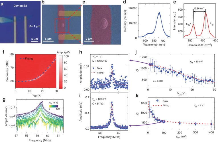
To study the Q vs. diameter relationship more comprehensively, we further scale down the resonators and measure a singly-isolated resonator, Device S2, with a 1 μm diameter (Fig. 3a) and monolayer thickness (Fig. 3d, e). The flat and smooth surface is confirmed by the SEM images (Fig. 3b, c) which show no observable residue or wrinkle. From the measured resonances (Fig. 3f, g), we extract Q factor at each VGS and vRF and obtain a Q factor up to 1051 ± 77 (Fig. 3h–k). By comparing the results from Figs. 2 to 3 we find that when the resonator surfaces are clean, the resonators with larger diameters have larger Q factors.
Fig. 3. Gate-tunable characteristics for a monolayer MoS2 circular drumhead resonator (Device S2) with flat suspended material and without observable surface nonidealities.
a Optical image of the device with a diameter of 1 μm. b, c False-colored SEM images showing the flat suspended membrane. Measured (d) photoluminescence spectrum with high intensity and (e) Raman spectrum with a difference between the E12g and A1g peaks of 19.86 cm−1, corresponding to monolayer MoS2. f Frequency tuning characteristics measured at a fixed vRF of 10 mV, with the amplitude shown in color scale. g Linear to nonlinear resonances obtained by increasing the vRF at a fixed VGS of 1 V. Extracted Q factors and modeled dependence on (j) VGS and (k) vRF, showing typical resonances at (h) VGS = 1 V with a Q factor of 1061 ± 107 and (i) vRF = 100 mV with a Q factor of 817 ± 21. From the gate-tunable Q factor, the loss angle δ of 0.008 is extracted from fitting via the strain-modulated dissipation model
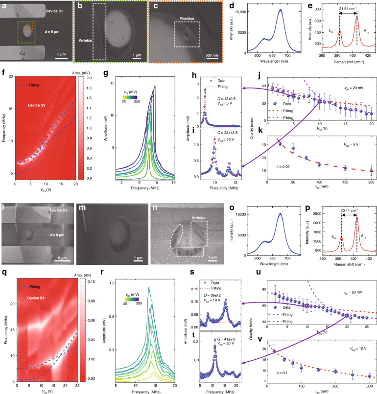
To further investigate the relationship between the Q factor and diameter, we measure 2D MoS2 NEMS resonators with larger diameters. For resonator Device S3 with a diameter of 6 μm (Fig. 4a) and bilayer thickness (Fig. 4d, e), the zoomed-in SEM images clearly show wrinkles (Fig. 4b) and residues (Fig. 4c) close to the clamping ends. From resonance measurements we find that the frequency tuning characteristics before and after VGS = 10 V show different increasing trends (Fig. 4f). The mode shapes, frequency tuning characteristics, and resonance curves of MoS2 NEMS resonators with surface residues or wrinkles under different damping conditions are simulated using the finite element method (FEM) (Figs. S18–S20), with abnormal mode shapes for the fundamental flexural mode observed. For the resonator with residue, we further demonstrate that the mode shape and the position of the maximum vibration amplitude change when the gate voltage increases (Fig. S18). The irregular mode shape at each VGS determines the dynamic energy in the device, which could result in nonideal frequency tuning characteristics and larger dissipation. The extracted Q factors at each VGS and vRF indicate that the Q factors are low and that Q decreases with increasing VGS and vRF (Fig. 4h–k). Fitting to the Q vs. VGS relationship also shows a turning point before and after VGS = 10 V, similar to the frequency tuning characteristics. The low Q factor and nonideal characteristics for gate tuning of Q factor suggest correlations with the dynamic-energy-dependent loss angle δ (Supporting Information Section S4 and Table S1), with resonators with larger diameters and lower Q factors generally having higher δ values. To confirm this effect, we further measure the frequency tuning characteristics of another device (Device S8) with the same 6-μm diameter (Fig. S7), which also has relatively low Q factors and nonideal resonance peak shapes.
Fig. 4. Gate tuning of frequency and dissipation characteristics and material characterization for two singly-isolated 2D MoS2 drumhead NEMS resonators with nonuniform membrane profiles.
a–k Characterization of Device S3. SEM images of Device S3 showing (a) the suspended membrane diameter of 6 μm with contact electrodes, (b) the zoom-in region in (a) showing the wrinkle, and (c) the zoom-in region in (b) showing the residue on the suspended membrane. d Photoluminescence spectrum. e Raman spectrum showing that the peak separation between the E2g1 and A1g peaks is 21.81 cm−1, corresponding to bilayer MoS2. f Frequency tuning characteristics measured by varying VGS from 0 V to 20 V with a fixed vRF of 20 mV, with the amplitude shown in color scale. g Measured linear to nonlinear resonances by varying vRF from 25 mV to 200 mV with a fixed VGS of 5 V. h–k Extraction of Q factors at varying gate voltages, showing (h) fitting to the resonance at VGS = 5 V, and (i) fitting to the resonance at VGS = 10 V. Summary of the measured Q factor and fitting to the dissipation model at varying (j) VGS, and (k) vRF, from which δ of 0.09 is extracted. l–v Measured characteristics of Device S4, with a diameter of 4 μm, shown in the same sequence as in (a–k). The SEM images in (l–n) also show some wrinkles. The measured Raman peak separation of 20.11 cm−1 in (p) corresponds to monolayer MoS2. From fitting to the measured gate tuning of the Q factor, a δ of 0.1 is extracted
For another MoS2 NEMS resonator (Device S4) with an even larger diameter of 8 μm and with a monolayer thickness (Fig. 4o, p), the SEM images also show that the suspended membrane contains several wrinkles (Fig. 4l–n). The frequency tuning characteristics (Fig. 4q) and Duffing nonlinearity (Fig. 4r) are also measured, but owing to the multiple spurious modes, the frequency tuning trend is not clear and cannot be fitted consistently using the model. Multiple resonance peaks show resonance frequencies similar to those of well-separated resonances, as predicted by the classical model (Fig. 4s, t)46, which could also be attributed to surface nonidealities. The nonideal frequency tuning characteristics and mode shapes due to wrinkles are simulated using FEM (Figs. S19–S20). The simulated resonance characteristics show that the spurious resonance modes become more obvious with greater vRF driving (Fig. S20). Furthermore, for resonators with small Q factors due to surface nonideality and large vRF, the resonance frequencies can also be close to each other, leading to merged resonances with a small peak for the spurious mode and a small frequency selectivity. These findings are consistent with the results presented in Fig. 1j. A summary of the fitting to all the resonances at various VGS and vRF also reveals low Q factors and decreasing Q factors with larger VGS and vRF, which cannot be fitted well above VGS = 15 V (Fig. 4u, v). To further confirm the consistency of the effects of diameter and surface nonideality on device properties, we obtain measurement results from 13 additional singly-isolated MoS2 drumhead NEMS resonators with various diameters (Devices S6–S18), which consistently show that larger membranes typically contain more surface nonidealities on the suspended membranes and thus have lower Q factors (Figs. S5–S17).
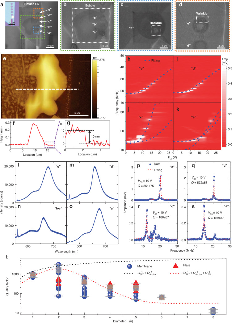
We further investigate Device S5, with an array of five microtrenches with the same diameter of 3 μm and uniform thickness of 10 nm (Fig. 5a, g) but with a large bubble on the surface formed during device fabrication (Fig. 5b, e). Despite having the same material and geometry, the five resonators in Device S5 have different surface nonidealities on the suspended membrane: resonators “b” and “c” are influenced by the bubble (Fig. 5e), resonator “a” has a residue on the suspended membrane (Fig. 5c), resonator “e” has a small wrinkle near the clamping edge (Fig. 5d), and resonator “d” has a very flat and clean suspended material (Fig. 5g). The PL intensities for resonators “b” and “c” are much lower than those for the other resonators (Fig. 5l–o), further confirming the effects of the bubble. We measure the resonance tuning characteristics of all five devices by varying VGS. Both resonators “e” and “d” show single clear resonances with high intensity so that the frequency tuning characteristics can be well fitted with our model (Fig. 5h, i). However, resonators “c” and “a” show multiple spurious modes in the resonances (Fig. 5j, k). The extracted Q factors for the flat resonator “d” without surface nonidealities are the highest for Device S5 (Fig. 5p–s), which shows that surface bubbles can also lead to larger dissipation. Resonator “e” with a small wrinkle has a lower Q factor than resonator “d” but a much higher Q factor than resonators “a” and “c”. These control experiments further confirm the importance of surface nonidealities for the resonance characteristics and damping properties of 2D NEMS resonators.
Fig. 5. Comparison of characteristics among 2D MoS2 NEMS resonators on 5 microtrenches next to each other in Device S5 with a bubble under the material.
a–d SEM images showing (a) 5 side-by-side resonators named “a”, “b”, “c”, “d”, and “e” with the same diameter of 3 μm. b Resonators “a”, “b”, and “c” with a large bubble outlined by the white dashed box. c Resonator “a” with residue on the membrane outlined by the white dashed box. d Resonator “e” with wrinkle in the white dashed box. e AFM image of the bubble area with the thickness shown in color scale. f, g Thickness profile measured along the white dashed lines in (a), showing (b) a maximum height of ~300 nm for the bubble and (c) a thickness of 10 nm for the MoS2 membrane. Gate tuning of the frequency measured by varying VGS from 0 V to 25 V and at a fixed vRF of 20 mV for resonators (h) “e”, (i) “d”, (j) “c”, and (k) “a”, with the amplitude shown in color scale. Resonator “b” does not show measurable resonance. Photoluminescence spectra measured at different positions for resonators (l) “e”, (m) “d”, (n) “b–c”, and (o) “a”. Comparison of typical measured resonances and extracted Q factors for different resonators at the same driving force, showing the Q factors of (p) 351 ± 75 for resonator “e”, (q) 572 ± 58 for resonator “d”, (r) 188 ± 37 for resonator “c”, and (s) 129 ± 37 for resonator “a”, at VGS = 5 V. t Summarized Q factors for all 52 MoS2 NEMS resonators and the modeled Q factor vs. diameter relationship, with diameters ranging from 1 μm to 8 μm. The Q factor shown for each device is the largest at varying gate voltages. The black dashed line is the model fitting using QTED−1 + QAnchor−1 (~D-1.1)43, and the red dashed line is the model fitting using QTED−1 + QAnchor−1 + QSN−1 (~D1.2) + QOther−1
The measurement results from all 52 MoS2 NEMS resonators consistently show that devices with large diameters (3–8 μm) generally have irregular resonance frequency tuning characteristics and many spurious modes, especially at large VGS, due to the higher chance of including surface nonidealities. In contrast, devices with smaller diameters (1–2 μm) show clear resonance modes with frequency and Q factor tuning characteristics well fitted by the models. We summarize the measured Q factor vs. diameter relationship in Fig. 5t, where the Q factor for each device is the largest Q factor at varying gate voltages. Because dissipation increases with a larger drive (|VGS × vRF|), the largest Q factor is usually obtained near the first measurable resonance at a small driving amplitude. The Q factor first increases and then decreases with increasing diameter, reaching a maximum value at 2 μm and a minimum value at 8 μm. We model the overall effect from multiple damping mechanisms as follows:
| 3 |
where QTED−1 represents thermoelastic dissipation, QAnchor−1 represents anchor loss, QSN−1 represents the loss induced by surface nonidealities, and QOther−1 represents other diameter-independent damping mechanisms including air/fluid damping, material-defect-induced damping, and phonon‒phonon dissipation. Surface-induced energy dissipation has been found to limit or decrease the Q factor as the device size increases47,48. For thermoelastic dissipation and anchor loss, a larger diameter can lead to a larger Q factor. When the diameter is 1–2 μm, thermoelastic dissipation and anchor loss dominate and the Q factor increases with diameter, reaching ~3315 at a diameter of 2 μm. When the diameter further increases, the damping induced by surface nonidealities becomes more important and the Q factors dramatically decrease to ~10 at a diameter of 8 μm. Therefore, to achieve high-Q factors in 2D NEMS resonators a clean, smooth, and high-quality suspended membrane is the key for minimizing surface-induced energy loss.
We consistently aim for high Q factor in NEMS devices as it is critical for potential applications of MoS2 NEMS resonators in terms of sensitivity, frequency stability, and power efficiency. Specifically, a decreased Q factor can reduce the sensitivity of the resonator to external stimuli, affecting its performance in sensing applications. Lower Q factors may result in reduced frequency resolution, limiting the accuracy of RF signal processing and communication. Larger damping can also increase energy dissipation leading to higher power consumption and reduced energy efficiency. When the resonator continues to scale down, the surface nonidealities are less significant, and several techniques can further minimize energy dissipation and enhance the Q factor. For example, optimizing the environment by reducing the temperature and vacuum pressure25,41,42, applying external tensile strain to the suspended membrane32, performing vacuum thermal annealing after transfer38, and growing and transferring high-quality 2D materials with fewer material defects can significantly reduce damping and enhance the Q factor49. Furthermore, developing fabrication techniques that can reduce surface nonidealities is important for further optimizing the Q factor. For example, employing a stress-free transfer process with the assistance of poly(methyl methacrylate) (PMMA) and growing uniform high-quality 2D materials can facilitate the fabrication of a large-scale array of 2D NEMS resonators29,50. This approach could help reduce wrinkles and residues on the resonators to further enhance the Q factor, but could be more time-consuming. Polymers such as SU-8 can provide support when 2D materials are released, but wet chemical processes are used16. Therefore, there is a growing need to develop simple fabrication techniques for producing high-quality 2D NEMS resonators with clean and flat surfaces.
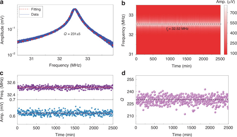
Given that long-term stability and reliability are critical for commercial and industrial applications, we measure Device 5-3 in Fig. 1a over time and summarize how the frequency and Q factor change. Initially, the device is placed in a vacuum chamber and the system is continuously pumped to evacuate air within the cavity and maintain a stable vacuum pressure. Subsequently, we maintain a fixed electric driving force and record the resonances for 500 times with a 5-min time gap. The measured resonances exhibit robust and repeatable characteristics over time (Fig. 6a), with stable vibration amplitudes, resonance frequencies, and Q factors (Fig. 6b–d). This robust and reliable operation of 2D MoS2 NEMS resonators makes them highly promising for applications in sensing, RF signal processing, and computing units.
Fig. 6. Long-term stability and reliability measurements of the MoS2 NEMS resonator Device 5-3 shown in Fig. 1a, with a diameter of 3 μm.
a Summary of all the measured resonance curves for 2500 min at VGS = 15 V and vRF = 50 mV, showing high stability and repeatability over time. The red dashed line is the fitting to the average curve, with an extracted Q factor of 231 ± 5. b Color map of resonances in (a) varying with time, showing a very stable resonance frequency of ~32.52 MHz (black dashed line), with the amplitude shown in color scale. Extracted (c) resonance frequency and amplitude and (d) Q factor varying with time for resonances within (a)
Conclusions
In summary, we measure 52 2D MoS2 NEMS resonators with varying diameters from 1 μm to 8 μm, and achieve the highest Q factor of 3315 ± 115 for a resonator with a diameter of 2 μm. This is achieved through optimizing the device geometry by considering the effects of surface nonidealities on dissipation, the competition between different damping mechanisms, and optimizing the driving conditions by considering the strain-modulated dissipation model. We further demonstrate the long-term stability of the resonators. This study sheds light on the mechanisms behind the previously observed low Q factor in 2D NEMS resonators and provides clear guidelines for designing high-Q 2D NEMS resonators, which is important for their applications in sensing, RF signal processing, quantum engineering, memory, and computing.
Supplementary information
Acknowledgements
The authors are thankful for support from the National Natural Science Foundation of China (NSFC) (Grants 92364107, U21A20505, 62104140, 62104241, 62250073), the Science and Technology Commission of Shanghai Municipality (STCSM) Rising-Star Program (Grant 23QA1405300), the General Program (Grant 21ZR1433800), the Natural Science Foundation of Chongqing (CSTB2022NSCQ-MSX1095), and the Lingang Laboratory Open Research Fund (Grant LG-QS-202202-11). We thank the Center for Advanced Electronic Materials and Devices (AEMD) of Shanghai Jiao Tong University, for the support in the fabrication and measurements of the devices.
Data availability
All the data needed to evaluate the conclusions in the paper are presented in the paper and/or the Supplementary Information. Other relevant data from this study are available from the corresponding author upon reasonable request.
Conflict of interest
The authors declare no competing interests.
Contributor Information
Hao Jia, Email: hao.jia@mail.sim.ac.cn.
Rui Yang, Email: rui.yang@sjtu.edu.cn.
Supplementary information
The online version contains supplementary material available at 10.1038/s41378-024-00763-9.
References
- 1.Bachtold, A., Moser, J. & Dykman, M. I. Mesoscopic physics of nanomechanical systems. Rev. Mod. Phys.94, 045005 (2022). [Google Scholar]
- 2.Wang, L., Zhang, P., Liu, Z., Wang, Z. & Yang, R. On-chip mechanical computing: status, challenges, and opportunities.Chip2, 100038 (2023). [Google Scholar]
- 3.Ekinci, K. L. & Roukes, M. L. Nanoelectromechanical systems. Rev. Sci. Instrum.76, 061101 (2005). [Google Scholar]
- 4.Schmid, S., Jensen, K. D., Nielsen, K. H. & Boisen, A. Damping mechanisms in high-Q micro and nanomechanical string resonators. Phys. Rev. B84, 165307 (2011). [Google Scholar]
- 5.Unterreithmeier, Q. P., Faust, T. & Kotthaus, J. P. Damping of nanomechanical resonators. Phys. Rev. Lett.105, 027205 (2010). [DOI] [PubMed] [Google Scholar]
- 6.Fang, D., Sun, Y. & Soh, A. K. Advances in thermoelastic damping in micro- and nano- mechanical resonators: a review. J. Solid Mech. Mater. Eng.1, 18–34 (2017). [Google Scholar]
- 7.Xu, B. et al. Nanomechanical resonators: toward atomic scale. ACS Nano16, 15545–15585 (2022). [DOI] [PMC free article] [PubMed] [Google Scholar]
- 8.Jung, M. et al. GHz nanomechanical resonator in an ultraclean suspended graphene p–n junction. Nanoscale11, 4355–4361 (2019). [DOI] [PubMed] [Google Scholar]
- 9.Ye, F., Islam, A., Zhang, T. & Feng, P. X.-L. Ultrawide frequency tuning of atomic layer van der waals heterostructure electromechanical resonators. Nano Lett.21, 5508–5515 (2021). [DOI] [PubMed] [Google Scholar]
- 10.Lee, J., Wang, Z., He, K., Yang, R., Shan, J. & Feng, P. X.-L. Electrically tunable single- and few-layer MoS2 nanoelectromechanical systems with broad dynamic range. Sci. Adv.4, eaao6653 (2018). [DOI] [PMC free article] [PubMed] [Google Scholar]
- 11.Lee, J., Shaw, S. W., & Feng, P. X. -L. Phononic frequency comb generation via 1:1 mode coupling in MoS2 2D nanoelectromechanical resonators. In Proc. IEEE 35th International Conference on Micro Electro Mechanical Systems (MEMS) 503–506 (IEEE, 2022).
- 12.Parmar, M. M., Gangavarapu, P. R. Y. & Naik, A. K. Dynamic range tuning of graphene nanoresonators. Appl. Phys. Lett.107, 113108 (2015). [Google Scholar]
- 13.Zhang, P., Jia, Y., Liu, Z. & Yang, R. Strain-enhanced dynamic ranges in two-dimensional MoS2 and MoTe2 nanomechanical resonators. Appl. Phys. Rev.11, 011410 (2024). [Google Scholar]
- 14.Weber, P., Güttinger, J., Noury, A., Vergara-Cruz, J. & Bachtold, A. Force sensitivity of multilayer graphene optomechanical devices. Nat. Commun.7, 12496 (2016). [DOI] [PMC free article] [PubMed] [Google Scholar]
- 15.Lee, J. et al. Self-sustaining MoS2 nanomechanical oscillators and feedback cooling. Appl. Phys. Lett.119, 243506 (2021). [Google Scholar]
- 16.Chen, C. et al. Graphene mechanical oscillators with tunable frequency. Nat. Nanotechnol.8, 923–927 (2013). [DOI] [PubMed] [Google Scholar]
- 17.Zhang, P. et al. Nanoelectromechanical memories based on nonlinear 2D MoS2 resonators. In Proc. IEEE 35th International Conference on Micro Electro Mechanical Systems (MEMS) 208–211 (IEEE, 2022).
- 18.Dash, A., More, S. K., Arora, N. & Naik, A. K. Ultra-sensitive charge detection and latch memory using MoS2-nanoresonator based bifurcation amplifiers. Appl. Phys. Lett.118, 053105 (2021). [Google Scholar]
- 19.Weber, P., Guttinger, J., Tsioutsios, I., Chang, D. E. & Bachtold, A. Coupling graphene mechanical resonators to superconducting microwave cavities. Nano Lett.14, 2854–2860 (2014). [DOI] [PubMed] [Google Scholar]
- 20.Singh, V., Bosman, S. J., Schneider, B. H., Blanter, Y. M., Castellanos-Gomez, A. & Steele, G. A. Optomechanical Coupling between a multilayer graphene mechanical resonator and a superconducting microwave cavity. Nat. Nanotechnol.9, 820–824 (2014). [DOI] [PubMed] [Google Scholar]
- 21.Xie, H., Jiang, S., Rhodes, D. A., Hone, J. C., Shan, J. & Mak, K. F. Tunable exciton-optomechanical coupling in suspended monolayer MoSe2. Nano Lett.21, 2538–2543 (2021). [DOI] [PubMed] [Google Scholar]
- 22.Lee, J., LaHaye, M. D. & Feng, P. X.-L. Design of strongly nonlinear graphene nanoelectromechanical systems in quantum regime. Appl. Phys. Lett.120, 014001 (2022). [Google Scholar]
- 23.Chen, C. et al. Modulation of mechanical resonance by chemical potential oscillation in graphene. Nat. Phys.12, 240–244 (2016). [Google Scholar]
- 24.Reserbat-Plantey, A. et al. Electromechanical control of nitrogen-vacancy defect emission using graphene NEMS. Nat. Commun.7, 10218 (2016). [DOI] [PMC free article] [PubMed] [Google Scholar]
- 25.Güttinger, J. et al. Energy-dependent path of dissipation in nanomechanical resonators. Nat. Nanotechnol.12, 631–636 (2017). [DOI] [PubMed] [Google Scholar]
- 26.Lee, J., Wang, Z., He, K., Shan, J. & Feng, P. X.-L. High frequency MoS2 nanomechanical resonators. ACS Nano7, 6086–6091 (2013). [DOI] [PubMed] [Google Scholar]
- 27.Zheng, X.-Q., Lee, J. & Feng, P. X.-L. Hexagonal boron nitride nanomechanical resonators with spatially visualized motion. Microsyst. Nanoeng.3, 2017 (2017). [DOI] [PMC free article] [PubMed] [Google Scholar]
- 28.Manzeli, S., Dumcenco, D., Migliato Marega, G. & Kis, A. Self-sensing, tunable monolayer MoS2 nanoelectromechanical resonators. Nat. Commun.10, 4831 (2019). [DOI] [PMC free article] [PubMed] [Google Scholar]
- 29.Barton, R. A. et al. High, size-dependent quality factor in an array of graphene mechanical resonators. Nano Lett11, 1232–1236 (2011). [DOI] [PubMed] [Google Scholar]
- 30.Zhang, X. et al. Dynamically-enhanced strain in atomically thin resonators. Nat. Commun.11, 5526 (2020). [DOI] [PMC free article] [PubMed] [Google Scholar]
- 31.Kramer, E., van Dorp, J., van Leeuwen, R. & Venstra, W. J. Strain-dependent damping in nanomechanical resonators from thin MoS2 crystals. Appl. Phys. Lett.107, 091903 (2015). [Google Scholar]
- 32.Zhang, P. et al. Strain-modulated dissipation in two-dimensional molybdenum disulfide nanoelectromechanical resonators. ACS Nano16, 2261–2270 (2022). [DOI] [PubMed] [Google Scholar]
- 33.Eichler, A., Moser, J., Chaste, J., Zdrojek, M., Wilson-Rae, I. & Bachtold, A. Nonlinear damping in mechanical resonators made from carbon nanotubes and graphene. Nat. Nanotechnol.6, 339–342 (2011). [DOI] [PubMed] [Google Scholar]
- 34.Keşkekler, A., Shoshani, O., Lee, M., van der Zant, H. S. J., Steeneken, P. G. & Alijani, F. Tuning nonlinear damping in graphene nanoresonators by parametric−direct internal resonance. Nat. Commun.12, 1099 (2021). [DOI] [PMC free article] [PubMed] [Google Scholar]
- 35.Ferrari, P. F., Kim, S. & van der Zande, A. M. Dissipation from interlayer friction in graphene nanoelectromechanical resonators. Nano Lett.21, 8058–8065 (2021). [DOI] [PubMed] [Google Scholar]
- 36.Jiang, J.-W. & Wang, J.-S. Why edge effects are important on the intrinsic loss mechanisms of graphene nanoresonators. J. Appl. Phys.111, 054314 (2012). [Google Scholar]
- 37.van der Zande, A. M. et al. Large-scale arrays of single-layer graphene resonators. Nano Lett.10, 4869–4873 (2010). [DOI] [PubMed] [Google Scholar]
- 38.Yang, R., Zheng, X., Wang, Z., Miller, C. J. & Feng, P. X.-L. Multilayer MoS2 transistors enabled by a facile dry-transfer technique and thermal annealing. J. Vac. Sci. Technol. B32, 061203 (2014). [Google Scholar]
- 39.Yang, R., Yousuf, S. E. H., Lee, J., Zhang, P., Liu, Z. & Feng, P. X.-L. Raman spectroscopic probe for nonlinear MoS2 nanoelectromechanical resonators. Nano Lett.22, 5780–5787 (2022). [DOI] [PubMed] [Google Scholar]
- 40.Zhang, P. et al. Probing linear to nonlinear damping in 2D semiconductor nanoelectromechanical resonators toward a unified quality factor model. Nano Lett.23, 9375–9382 (2023). [DOI] [PubMed] [Google Scholar]
- 41.Lee, J., Wang, Z., He, K., Shan, J. & Feng, P. X.-L. Air damping of atomically thin MoS2 nanomechanical resonators. Appl. Phys. Lett.105, 023104 (2014). [Google Scholar]
- 42.Zhang, P. et al. Enhanced quality factor in 2D NEMS resonators by optimizing air damping and thermoelastic damping. In Proc. IEEE 37th International Conference on Micro Electro Mechanical Systems (MEMS) 923–926 (IEEE, 2024).
- 43.Wilson-Rae, I. et al. High-Q nanomechanics via destructive interference of elastic waves. Phys. Rev. Lett.106, 047205 (2011). [DOI] [PubMed] [Google Scholar]
- 44.Lee, C., Yan, H., Brus, L. E., Heinz, T. F., Hone, J. & Ryu, S. Anomalous lattice vibrations of single and few-layer MoS2. ACS Nano4, 2695–2700 (2010). [DOI] [PubMed] [Google Scholar]
- 45.Pillai, G. & Li, S.-S. Piezoelectric MEMS resonators: a review. IEEE Sens. J.21, 12589–12605 (2021). [Google Scholar]
- 46.Graff, K.F. Wave Motion in Elastic Solids (Dover Publications, 1991).
- 47.Yasumura, K. et al. Quality factors in micron- and submicron-thick cantilevers. J. Microelectromech. Syst.9, 117–125 (2000). [Google Scholar]
- 48.Yang, J., Ono, T. & Esashi, M. Surface effects and high quality factors in ultrathin single crystal silicon cantilevers. Appl. Phys. Lett.77, 3860–3862 (2000). [Google Scholar]
- 49.Liu, Z. et al. Wafer-scale synthesis of two-dimensional materials for integrated electronics. Chip3, 100080 (2024). [Google Scholar]
- 50.Liu, Z. et al. Polymethyl methacrylate (PMMA) pyrolysis assisted transfer of 2D materials for large-scale molybdenum disulfide NEMS resonator arrays. In Proc. IEEE 37th International Conference on Micro Electro Mechanical Systems (MEMS) 677–680 (IEEE, 2024).
Associated Data
This section collects any data citations, data availability statements, or supplementary materials included in this article.
Supplementary Materials
Data Availability Statement
All the data needed to evaluate the conclusions in the paper are presented in the paper and/or the Supplementary Information. Other relevant data from this study are available from the corresponding author upon reasonable request.


