Abstract
This study explores the characteristics and potential engineering applications of Cu–Al–Mn and Cu–Al–Be–Mn shape memory alloys (SMAs). The research investigates the chemical composition, transformation temperatures, and mechanical properties of these SMAs when incorporated into Al metal matrix composites (MMCs). It was found that the addition of Mn and Be, has a significant impact on the performance of Cu–Al alloys. Among Cu–Al–Mn SMAs, SMA1, with a composition of Cu-80.94%, Al-10.54%, and Mn-8.52%, exhibited superior strain recovery, super elasticity (SE), and improved mechanical properties compared to other compositions. The study also demonstrates that the inclusion of SMA fibres in Al composites enhances residual strength, energy absorption capacity, and the ability to close fissures, contributing to a more robust and resilient material. In the case of Cu–Al–Be–Mn SMAs, SMA6, with Cu-87.42%, Al-11.8%, Be-0.48%, and Mn-0.3%, showcased improved properties, outperforming other compositions in terms of strain recovery, residual strength, energy absorption capacity, and crack-closing ability. These findings suggest that Cu–Al–Be–Mn SMAs hold promise for various engineering applications. The study provides valuable insights into the potential of these SMAs to enhance the performance of structural materials, offering increased strength, ductility, and resilience. This research contributes to a deeper understanding of the applications and advantages of SMAs in the field of engineering.
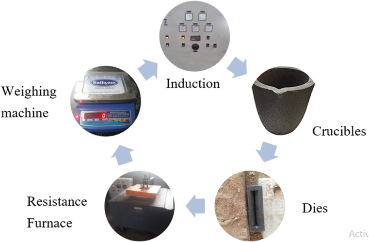
Overall casting experimental setup.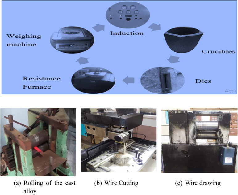
1. Introduction
Smart materials have the remarkable ability to sense and are widely utilized in various sectors like robotics, structural engineering, biomedicine, and aerospace technology. Within the realm of smart materials, SMAs stand out due to their distinctive features. They can return to their original shape after deformation, achieved either through changes in temperature (known as the shape memory effect (SME)) or by relieving applied stress (referred to as pseudo elasticity) and retention of SME even after extensive mechanical cycling. These traits SE and the SME, set SMAs apart as smart materials with exceptional capabilities. SE is the capacity to recover to a predetermined shape after experiencing significant nonlinear deformation. In simpler terms, after the applied stress is removed, any inelastic distortion occurring beyond the austenite completion temperature (Af) can promptly revert to its initial state. This suggests that after unloading, inelastic deformation persists but recovers when the alloy is heated to a temperature above Af. Since their creation in the 1960s, the SMAs have mostly been utilized in the fields of medical, aeronautical, and automotive engineering.1–4
The concept of SME was first observed by Chang and Read in the case of an Au–Cd alloy approximately in 1951. Subsequently, in 1953, a similar effect was reported in an In–Tl alloy.5 It wasn't until 1962, that William J. Buehler discovered a remarkable SMA, which he aptly named “Nitinol” as a tribute to the Naval Ordnance Laboratories. This alloy exhibited excellent strain recovery properties and demonstrated remarkable thermal stability.6 The use of SMAs in the fields of architectural and civil engineering has recently been expanded. Controlling oscillations brought on by outside forces like winds, earthquakes, and traffic is especially important for buildings and bridges because they can lead to progressive failure and damage.7–9 SMAs in the wire form and plates have been utilized to control the behavior of the structural components and to offers resistance to the external loads. The energy loss, secant stiffness, residual strain, and equivalent damping of the SMA wires were investigated by Dolce10 and Cardone11 using tensile testing and cyclic torsion. Results demonstrated that the SMA wires had a significant capacity for energy dissipation and fatigue resistance, making them an excellent choice for utilize as the seismic device. Using SMA's super elastic and damping properties, Mekki and Auricchio12 proposed an energy dissipation machine for cables in the cable-stayed bridges. They evaluated the impact of the SMA device's area, length, and location on the ability to regulate cable movement.
Torra et al.,13 examined regarding effectiveness of the SMA wire dampers in stayed cables included recommendations for the quantity and length of SMA wires that should be used. SMA wire dampers were suggested by Zhang and Zhu14 as a means of regulating a three-story building's seismic reaction. The suggested dampers of SMA for dissipation of large energy during earthquakes use a SMA wire. To improve the seismic performance of structures, deformation control machines such as connections, braces and base isolators had suggested in addition to dampers.15–18
Pre-stressing or strengthening of concrete and structural elements has been the subject of studies.19–21 An experimental investigation was undertaken by Abdulridha and Palermo22 to evaluate the enactment of a SMA steel-reinforced concrete thin shear wall that demonstrated significant displacement restitution after subjected to significant drifts. A promising method for strengthening the walls of old buildings was developed by Branco et al.,23 by using the hysteretic behaviour of the wires to reinforce a composite wall. For strengthening reinforced concrete structures, Shahverdi et al.,24 exploited the iron-based SMA strips, which emerges from recovery stress due to their mechanical fixation and reported enhancement of SMA's use and functionality in cement-based members. Beam specimens with dimensions of 160 mm in length and 40 mm in width were created. SMA fibres were dispersed at random with cementitious components. The SMA fibre-reinforced cement composites were then solely applied to the bottom of the beams, which is also the area where the beams are most prone to cracking. Cu–Al–Mn was the major component of the SMA fibres. To protect the cementitious material during the heating process, the austenite finish temperature was set at or near 100 °C. To assess the tensile flexural strength, a four-point bending test was carried out, and during the test, cracks appeared at the bottom of the beam. Subsequently, the SME was initiated, and the closed crack's width was assessed by employing a heating plate that could be affixed to the lower part of the beam. For various fibre volume fractions, specifically 0.25%, 0.5%, 0.75%, and 1%, the examination aimed to pinpoint the influence of SMA fibres on the beams' capacity to close cracks and their flexural tensile strength.
Many works focused on Cu-based SMAs involving economical materials viz, Cu–Al–Mn Cu–Zn–Al, Cu–Al–Ni, Cu–Al–Be–Mn and Cu–Zn–Si.25,26 Cu–Al–Be–Mn alloy possess good mechanical characteristics, corrosion resistance, SE, capacity to absorb vibration finds application in petroleum industry for pipe joints as Be reduces phase transformation temperatures.27 Candido et al.,28 conducted a comprehensive examination of a Cu–Al–Be alloy, wherein chromium (Cr) was introduced as a grain-refining agent. Their investigation encompassed both microstructural and mechanical assessments. Notably, the microscopic analyses unveiled a remarkable reduction in grain size, with values diminishing from 1950 μm to 100 μm for samples containing 0.5 wt% Cr and those devoid of Cr (0 wt%), respectively. One noteworthy outcome emerged when they evaluated the alloy containing 0.2 wt% Cr. Hence, an increase in the chromium (Cr) content in the Cu–Al–Be alloy leads to a more pronounced effect in grain refinement. This specific composition demonstrated enhanced tensile stress–strain characteristics. Additionally, it exhibited a notable reduction in martensitic transformation temperatures. These findings suggest that this particular alloy composition may offer distinct advantages for applications involving low-temperature conditions.
In a study by Gowda et al.,29 it was noted that the introduction of Be into the Cu–Al binary system led to a significant reduction in transformation temperatures, with some transformations occurring at or below room temperature. Concurrently, Higuchi and colleagues30 examined the connection between element composition and transformation temperatures. The research revealed that the incorporation of 0.1 wt% Be into the Cu–Al SMA resulted in a substantial decrease of approximately 100 °C in phase transformation temperatures. Oliveira et al.,31–33 in a series of studies explored the potential of Cu-based shape memory alloys, such as Cu–17Al–11.4Mn and Cu–Al–Be, as substitutes for NiTi due to lower costs and improved mechanical properties. The first study focused on Cu–17Al–11.4Mn, revealing enhanced ductility in the fusion zone and superior superelasticity. The second study introduced post-weld laser processing, resulting in increased tensile strength and energy absorption for seismic applications. The third study investigated laser welding of single crystal-like Cu–Al–Be alloys, yielding defect-free joints with preserved superelastic behavior and high energy absorption, making them promising for damping applications in seismic systems. The study of Ni–Al–Ti based SMA by Babu K. N. et al., delves into the characteristics of these alloys, aiming to understand how different compositions impact wear behavior. The study utilizes experimental methods to assess wear properties, providing insights into the suitability of NiTiAl SMAs for specific applications.34 The research on similar SMA by Santhosh N. et al., combines experimental and analytical approaches to comprehensively study the mechanical behaviors of SMAs for medical applications. The emphasis on biomedical applications suggests a consideration of the alloys for use in medical devices, with potential insights into their performance and reliability in such specialized settings.35 Overall, these studies advanced the understanding of weldability and mechanical properties, expanding the potential of shape memory alloys in various engineering applications.
However, not much information is available on Cu–Al–Mn based SMA fibres reinforced in Al matrix and their mechanical properties and transformation temperatures, since most of the works are focused on nitinol-based alloys systems and only incipient findings are available on Cu based SMA systems. Hence to address this gap, the current study is planned. The primary objective of this study is to synthesize SMAs of Cu–Al–Mn and Cu–Al–Be–Mn and study the chemical composition, transformation temperatures and the effect of fibre volume percentage on the mechanical properties of the Al matrix reinforced with SMA wires for specific engineering applications.
2. Materials and methods
This section discusses synthesis of different SMA alloys of Cu–Al–Mn, Cu–Al–Mn–Be with varied proportions of individual contents.
2.1. Casting of Cu–Al–Mn, Cu–Al–Be–Mn SMA
The research focused on Cu based SMAs that contained varying compositions of Al, ranging from 10 to 14.5 wt%, and Mn, ranging from 0 to 10 wt%. These specific alloy compositions were selected to ensure the presence of the β-phase and to observe the SME. Roughly 500 grams of the alloy were melted in a crucible coated with graphite under an argon atmosphere using a resistance-heated furnace. Subsequently, the molten alloy was poured into a cast iron mold with dimensions of 0.15 m × 0.10 m × 0.006 m and allowed to cool and solidify.
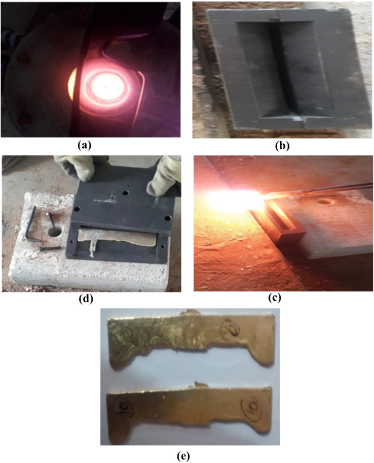
To refine the resulting ingots, a homogenization process was carried out at a temperature of 1173 K, which falls within the β-phase range. This process lasted for 21.6 kiloseconds and was conducted in an argon atmosphere. The exact compositions of the cast alloys were determined using an optically coupled plasma-optical emission spectrometer (OCP-OES). Fig. 1 depicts the visual representation of the casting procedure employed in synthesizing the SMA's.
Fig. 1. Casting process of Cu–Al–Mn & Cu–Al–Be–Mn SMA alloys. (a) Vacuum melting. (b) Dieset up used in the process (c) pouring of the molten alloy. (d) Fettling and cleaning of solidified alloy. (e) Cast SMA alloys after fettling and cleaning.
Cu based SMAs were prepared by varying the content of Al–Mn and Al–Mn–Be, as indicated in Tables 1 and 2 respectively. The process involved melting 500 g of pure Cu, Al, and Be pieces for each specific alloy in an induction furnace. After melting, the molten alloy was poured into a cast iron mold with dimensions of 0.15 m × 0.10 m × 0.006 m and left to solidify. Subsequently, the resulting ingots underwent a homogenization process at 1173 K for a duration of 6 hours. The alloy compositions were accurately determined using an OCP-OES. Fig. 2 shows the overall experimental setup used in the casting of Cu–Al–Mn and Cu–Al–Be–Mn SMA's.
Chemical composition of Cu–Al–Mn SMAs.
| Samples | Composition (wt %) | ||
|---|---|---|---|
| Cu | Al | Mn | |
| SMA 1 | 80.94 | 10.54 | 8.52 |
| SMA 2 | 81.10 | 10.81 | 8.10 |
| SMA 3 | 83.52 | 11.36 | 5.12 |
Chemical composition of Cu–Al–Mn–Be SMAs.
| Samples | Composition (wt %) | |||
|---|---|---|---|---|
| Cu | Al | Be | Mn | |
| SMA 4 | 88.38 | 11.0 | 0.42 | 0.2 |
| SMA 5 | 87.85 | 11.5 | 0.45 | 0.3 |
| SMA 6 | 87.42 | 11.8 | 0.48 | 0.3 |
Fig. 2. Schematic of the overall casting experimental setup.
2.2. Al metal matrix composites with SMA fibres reinforcement
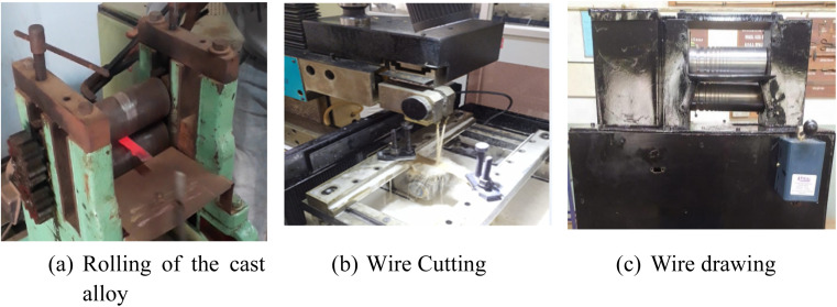
Fig. 3 shows the rolling, cutting and wire drawing machines used in the development of SMA fibres from Cu–Al–Mn and Cu–Al–Be–Mn combinations respectively. The wires of 0.8 mm diameter were reinforced with Al matrix using frame mounting attachments embedding the SMA's.
Fig. 3. Steps in SMA fibre synthesis process (a) rolling of the cast alloy, (b) wire cutting, (c) wire drawing.
2.3. Preparation of SMA fibres reinforced Al alloys for notched specimens
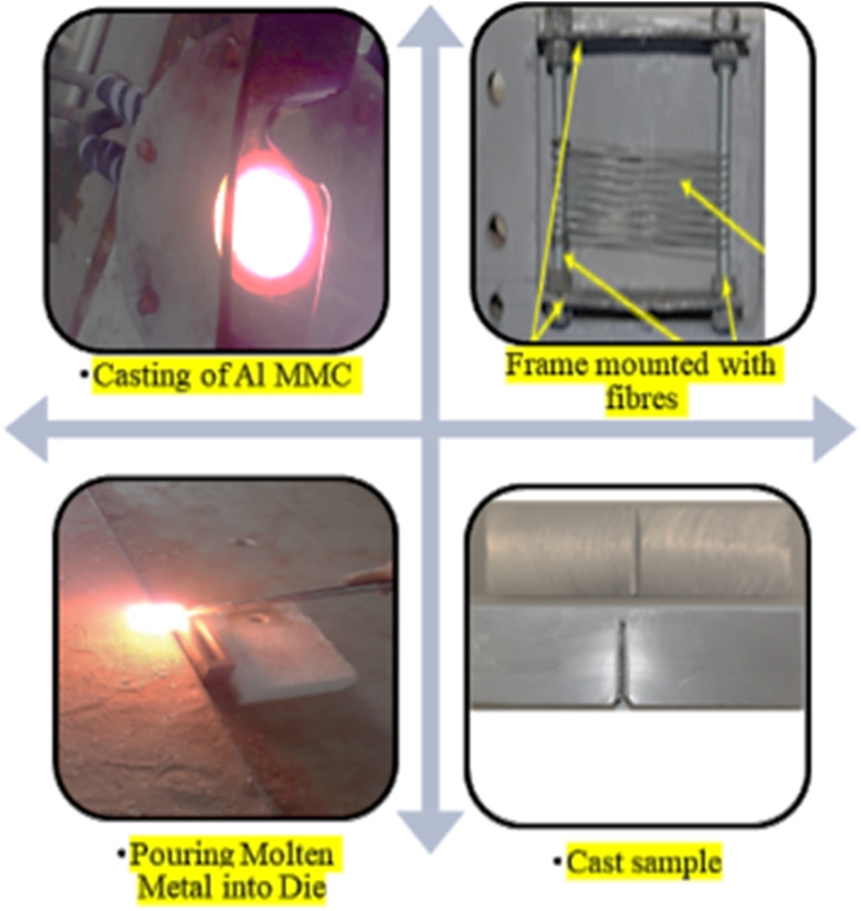
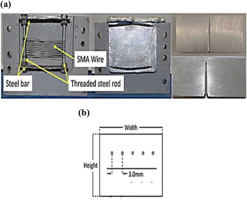
Fig. 4 shows Al alloy reinforced with Cu–Al–Mn and Cu–Al–Be–Mn SMA fibres during fabrication of the notched specimens with reinforcement arrangement used. Fig. 5a shows the synthesis of Cu–Al–Mn and Cu–Al–Be–Mn SMA alloys (left and center) notched before and after cracking sample (right) and Fig. 5b shows the schematic of reinforcement arrangement.
Fig. 4. Preparation of Al metal matrix composites (MMCs).
Fig. 5. (a) Photograph of frame arrangement used for reinforcing the SMA fibres in the Al-matrix (left and centre), notched specimens before and after cracking (right). (b) Schematic of reinforcement arrangement.
Strengthening aluminum castings with Shape Memory Alloy (SMA) fibers involves a systematic process to create high-performance notched specimens for crack test. The initial step involves carefully selecting an appropriate SMA material, Cu–Al–Mn and Cu–Al–Be–Mn in the present case, tailored to the application's specific requirements. SMA fibers are then meticulously prepared in the desired form, woven around a threaded steel rod, and undergo surface treatment, viz., roughening by emery paper, to enhance adhesion to the aluminum matrix. The aluminum matrix is prepared with consideration for accommodating the thermal expansion and contraction of SMA fibers during casting by heating in a crucible at 650 °C in a gas fired furnace and degassing using the Coverall flux before integration. Integration of SMA fibers into the aluminum matrix is achieved two methods either by adding them to molten aluminum or incorporating them into the mold during casting. In the present work, it is incorporated into the mold during casting with the help of steel frame attached to the die. Controlled cooling minimizes thermal stresses, while a post-casting heat treatment optimizes mechanical properties. Thorough testing and quality control, focusing on parameters like tensile strength, hardness, and wear resistance, guide optimization and iteration of the casting process or material composition. Tailoring the strategy to application-specific needs, such as temperature and corrosion resistance, is crucial. The controlled integration of the SMA fibres into the Aluminum matrix for the preparation of the notched specimens regulates the performance criteria, while considering challenges like cost and processing difficulties associated with SMA fibers.
2.4. Characterization of SMA fibres reinforced aluminium composites
The characterization of the shape memory alloys (SMAs) reinforced aluminium composite in the study was carried out using several key techniques. Optical Emission Spectroscopy (OES) was employed to accurately determine the chemical composition of the SMA samples after casting on a Thermo Fisher make OES Spectrometer. While not explicitly mentioned, X-ray Diffraction (XRD) is typically used to identify and confirm the phases present in the alloys, such as martensite and austenite, by analyzing the crystalline structure using Bruker make D8 Endeavour XRD machine. Differential Scanning Calorimetry (DSC) was utilized to measure the critical transformation temperatures (Mf, Ms, As, Af), viz.
Mf: Martensite finish temperature – the temperature at which the transformation to martensite is complete upon cooling.
Ms: Martensite start temperature – the temperature at which the transformation to martensite begins upon cooling.
As: Austenite start temperature – the temperature at which the transformation to austenite begins upon heating.
Af: Austenite finish temperature – the temperature at which the transformation to austenite is complete upon heating.
These temperatures are essential for understanding the shape memory effect and super elasticity of the alloys using Hitachi make DSC Nexta equipment.
Scanning Electron Microscopy (SEM) accomplished on a Hitachi make SU 3500 machine provide detailed images of the microstructure, revealing features like grain size, phase distribution, and surface morphology. This technique was likely coupled with Energy-Dispersive X-ray Spectroscopy (EDX), which allows for elemental analysis to ensure that the elemental distribution within the SMA aligns with the intended composition. These combined characterization methods offer a comprehensive understanding of the SMAs' chemical and physical properties, ensuring the accuracy and reproducibility of the experimental findings.
3. Results and discussion
3.1. Effect of varying content of Al and Mn on the performance of Cu–Al–Mn SMAs
This section discusses the chemical composition, transformation temperatures, SME and super elasticity (SE) of Cu–Al–Mn SMAs with varied proportions of Al and Mn respectively. Table 3 shows Cu–Al–Mn based SMAs viz, with varied content of Cu, Al and Mn respectively. Among these SMAs, SMA1 showed lower transformation temperature compared to SMA2 and SMA3 respectively.
Chemical composition and transformation temperature of SMAs alloys of Cu–Al–Mn.
| Sample number | Composition (wt %) | Transformation temperature (K) | |||||
|---|---|---|---|---|---|---|---|
| Cu | Al | Mn | M f | M s | A s | A f | |
| SMA 1 | 80.94 | 10.54 | 8.52 | 306 | 322 | 325 | 339 |
| SMA 2 | 81.10 | 10.81 | 8.10 | 334 | 358 | 346 | 370 |
| SMA 3 | 83.52 | 11.36 | 5.12 | 370 | 390 | 391 | 416 |
3.1.1. Effect of Al and Mn content on chemical composition, transformation temperatures of Cu–Al–Mn SMAs
In order to study the effect of Al content with Mn content fixed on the transformation temperature two other SMAs viz, SMA 1N and SMA 2N were developed as shown in Table 4. Keeping Al constant and increasing the Mn concentration decreases the transformation temperature and increases the strain recovery.
Chemical composition and transformation temperature of SMAs alloys of Cu–Al–Mn with constant Al content.
| Sample number | Composition (wt %) | Transformation temperature (K) | Strain recovery (%) | SE (%) | |||||
|---|---|---|---|---|---|---|---|---|---|
| Cu | Al | Mn | M f | M s | A s | A f | |||
| SMA 1N | 80.94 | 12 | 7.06 | 282 | 299 | 304 | 319 | 79 | 8 |
| SMA 2N | 82 | 12 | 6.0 | 294 | 318 | 321 | 341 | 91 | 7 |
| SMA 1 | 80.94 | 10.54 | 8.52 | 306 | 322 | 325 | 339 | 95 | 8 |
| SMA 2 | 81.10 | 10.81 | 8.10 | 334 | 358 | 346 | 370 | 89 | 7 |
| SMA 3 | 83.52 | 11.36 | 5.12 | 370 | 390 | 391 | 416 | 90 | 8 |
To further study the effect of varying Mn and constant Al on the transformation temperature, the following new SMAs viz, SMA 3N and SMA 4N were considered as shown in Table 4. Keeping Mn constant and reducing the Al increases the transformation temperature.
The transformation temperatures in shape memory alloys (SMAs) are closely influenced by the alloy's composition, particularly the levels of aluminum (Al) and manganese (Mn). Changes in the content of these elements can significantly impact the stability of different phases and the energy needed for phase transformations.
Increasing Al content generally stabilizes the austenite phase (β-phase), leading to higher transformation temperatures (As and Af). This is because Al raises the energy barrier for the martensite-to-austenite transformation, requiring more thermal energy (higher temperature) for this transition during heating.
Conversely, higher Mn content tends to lower the martensite start (Ms) and finish (Mf) temperatures. Mn affects the alloy's lattice parameters and stabilizes the martensite phase, making it easier for the material to transform to martensite at lower temperatures while influencing the overall phase transformation behavior.
The paper indicates the presence of different allotropic phases (such as β-phase and martensite) in the materials studied. X-ray Diffraction (XRD) analysis has been added, providing clear evidence of the phases present in the Cu–Al–Mn and Cu–Al–Be–Mn alloys at various temperatures. This confirms the presence of the β-phase at high temperatures and martensitic phases at lower temperatures.
Additionally, Differential Scanning Calorimetry (DSC) data has been incorporated to delineate the transformation temperatures (Mf, Ms, As, Af) for each alloy composition, offering a comprehensive understanding of the thermal behavior and phase transitions in these alloys. The inclusion of Scanning Electron Microscopy (SEM) images further supports this, showing microstructural changes corresponding to the phase transitions and providing visual confirmation of the martensitic variants.
The discussion section has been enhanced to explore the impact of phase stability on material properties, including mechanical strength, super elasticity, and fatigue resistance. A comparative analysis between different alloy compositions has been provided, highlighting how variations in phase stability influence their performance in engineering applications. The Table 5 gives the compilation of the results from XRD, DSC and EDAX with chemical composition and transformation temperatures.
Chemical composition and transformation temperature of SMAs alloys of Cu–Al–Mn with constant Mn content.
| Sample number | Composition (wt %) | Transformation temperature (K) | Strain recovery (%) | SE (%) | |||||
|---|---|---|---|---|---|---|---|---|---|
| Cu | Al | Mn | M f | M s | A s | A f | |||
| SMA 3N | 81 | 13 | 6 | 295 | 317 | 321 | 341 | 93 | 6 |
| SMA 4N | 83 | 11 | 6 | 322 | 346 | 342 | 368 | 89 | 7 |
| SMA 1 | 80.94 | 10.54 | 8.52 | 306 | 322 | 325 | 339 | 95 | 8 |
| SMA 2 | 81.10 | 10.81 | 8.10 | 334 | 358 | 346 | 370 | 89 | 7 |
| SMA 3 | 83.52 | 11.36 | 5.12 | 370 | 390 | 391 | 416 | 90 | 8 |
3.1.2. Effect of Al and Mn content on SME and SE of Cu–Al–Mn SMAs
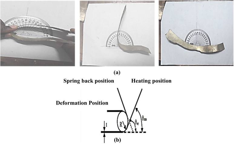
Fig. 6a shows the photographic view of shape recovery determination for the SMAs synthesized. Shape memory strain recovery were determined for these SMA alloys as shown in Table 2.
Fig. 6. (a). Photographic view and (b) schematic view of shape recovery calculation.
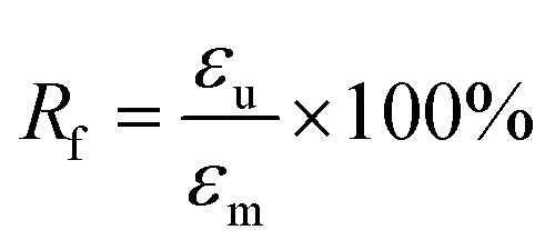
Fig. 6b shows the schematic view of shape recovery determination for the SMAs synthesized. The shape fixity (Rf) and the shape recovery (Rr) were evaluated with the following eqn (1) and (2).
 |
1 |
 |
2 |
where εu is the original unloading strain, εm is the original maximum strain, εp is the residual strain.
From Table 6, it follows that for Cu–Al–Mn SMAs, the SMA1 showed higher strain recovery which increased by 6.74% and 5.55% compared to SMA 2 and SMA3 respectively.
Shape memory strain recovery in Cu–Al–Mn alloys.
| Sample number | Strain recovery (%) |
|---|---|
| SMA 1 | 95 |
| SMA 2 | 89 |
| SMA 3 | 90 |
From Table 7 it follows that for Cu–Al–Be–Mn SMAs, the SMA6 showed higher strain recovery which increased by 45.45 and 9.1% compared to SMA 4 and SMA 5 respectively.
Shape memory strain recovery in Cu–Al–Be–Mn.
| Sample number | Strain recovery (%) |
|---|---|
| SMA 4 | 66 |
| SMA 5 | 88 |
| SMA 6 | 96 |
3.2. Shape memory effect (SME) and super elasticity (SE)
The extent of strain recovery and SE of all the SMEs considered in the study is given in Table 8.
SME and SE of Cu–Al–Mn SMAs.
| Sample number | Strain recovery (%) | SE (%) |
|---|---|---|
| SMA 1N | 79 | 8 |
| SMA 2N | 91 | 7 |
| SMA 3N | 94 | 5 |
| SMA 4N | 90 | 6 |
| SMA 1 | 95 | 7 |
| SMA 2 | 89 | 7 |
| SMA 3 | 90 | 8 |
The SMAs have shown substantial strain recovery through the SME, ranging from 79% to 95%. As indicated in Table 8, it can be observed that the composition of the alloy has little impact on strain recovery through SME, except for SMA 1N. The primary factor influencing strain recovery via SME is the extent of martensite-to-austenite transformation within the alloy system. The presence of any remaining martensite within the austenite phase of the alloy will proportionally reduce strain recovery.34 Other variables, such as material imperfections like quenched-in vacancies and dislocations, have an effect on strain recovery through SME. These imperfections cause the martensitic plates to be pinned, thereby impeding the transformation process and, consequently, strain recovery. Alloys with higher concentrations of Al and Mn exhibit greater strain recovery through SME. This may be attributed to the ease with which the transformation from martensite to austenite occurs, leading to lower transformation temperatures.
3.3. Cu–Al–Be–Mn SMA alloys
This section discusses the chemical composition, transformation temperatures, SME and SE of Cu–Al–Be–Mn SMA alloys.
3.3.1. Chemical composition and transformation temperature of Cu–Al–Be–Mn SMA alloys
Chemical composition, transformation temperatures, SME and SE of Cu–Al–Be–Mn SMAs are shown in Table 9. Among these SMAs, SMA6 showed lower transformation temperature compared to SMA4 and SMA5 respectively with increasing content of Be and Mn respectively. Addition of Be content in Cu–Al–Mn SMAs showed comparatively lower transformation temperatures.
Chemical composition and transformation temperature of SMAs alloys of Cu–Al–Be–Mn.
| Sample number | Composition (wt %) | Transformation temperature (K) | ||||||
|---|---|---|---|---|---|---|---|---|
| Cu | Al | Be | Mn | M f | M s | A s | A f | |
| SMA 4 | 88.38 | 11.0 | 0.42 | 0.2 | 316 | 325 | 331 | 354 |
| SMA 5 | 87.85 | 11.5 | 0.45 | 0.25 | 311 | 346 | 334 | 367 |
| SMA 6 | 87.42 | 11.8 | 0.48 | 0.3 | 302 | 314 | 324 | 333 |
3.4. Mechanical properties of Cu–Al–Mn and Cu–Al–Be–Mn SMA alloys
This section discusses the testing of SMA based composites to determine the mechanical properties such as residual strength, energy absorption capacity, cracking strength and cracking widths respectively.
3.4.1. Residual strength or percentage of shape recovery (strains) of SMA alloys
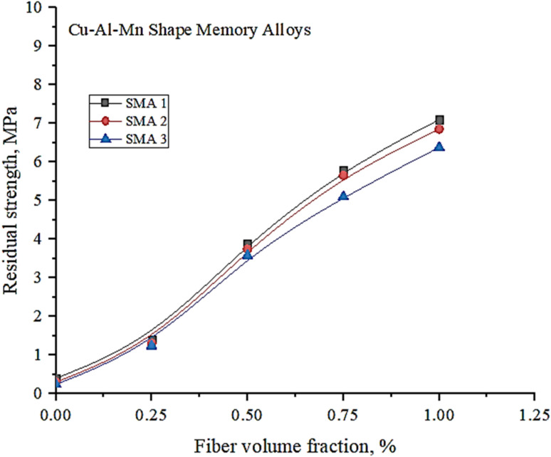
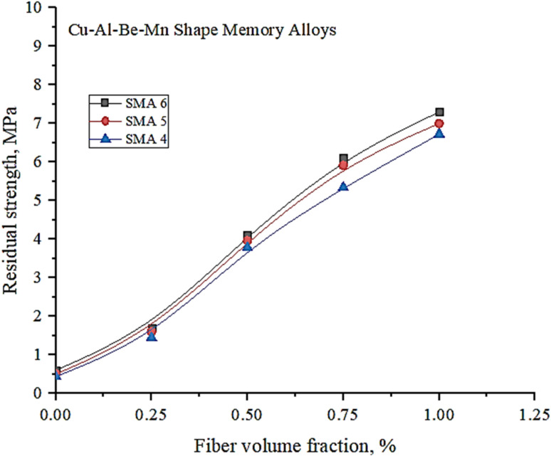
Fig. 7 and 8 illustrate the changes in residual strength in two types of SMAs: Cu–Al–Mn and Cu–Al–Be–Mn. These SMAs were infused with varying fibre volumes, ranging from 0 to 1.00%. Notably, the beams entrenched with SMA fibres exhibited an increase in residual flexural strength as the fibre volume fraction increased. This is in stark contrast to the control specimens lacking SMA fibres, which exhibited immediate deterioration after cracking.
Fig. 7. Variation of residual strength with fibre volume fraction of Cu–Al–Mn SMA alloys.
Fig. 8. Variation of residual strength with fibre volume fraction of Cu–Al–Be–Mn SMA alloys.
The post-cracking residual strength remained intact in the SMA fibre-embedded beams, with only a minor reduction in flexural strength. Among the tested SMAs, SMA1 displayed a higher residual strength due to the increased addition of Mn to the binary Cu–Al alloy. This addition stabilized the BCC phase, resulting in a lower temperature range for the existence of the β-phase. Consequently, this expanded the composition range, enhancing the alloy's ductility and reducing the degree of order.23,24
Similar trends were observed in Cu–Al–Be–Mn SMA alloys, with SMA 6 demonstrating higher residual strength due to the increased incorporation of Be. Notably, Cu–Al–Be–Mn SMAs exhibited superior residual strength when compared to Cu–Al–Mn SMAs.
3.4.2. Energy absorption capacity of SMA alloys
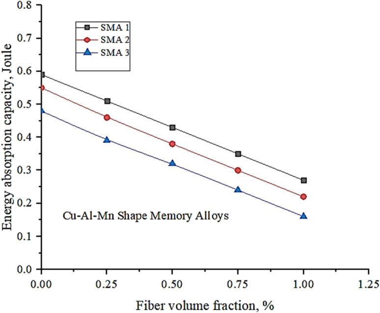
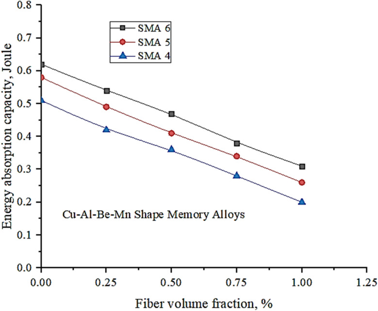
Fig. 9 and 10 shows variation of energy absorption capacity, which varies with fibre volume percentage. Energy absorption capacity can be determined by either analyzing the load and deflection data up to a specific point or by assessing the areas beneath the load and deflection curves and former method is adopted in the present study.
Fig. 9. Variation of energy absorption capacity with fibre volume fraction of Cu–Al–Mn SMA alloys.
Fig. 10. Variation of energy absorption capacity with fibre volume fraction of Cu–Al–Be–Mn SMA alloys.
A slight decrease in energy absorption capacity is obtained with a rise in fibre volume percentage which is consistent with SMA fibres having little effect on energy absorption capacity. SMA 1 showed higher energy absorption capacity compared to other coupons as higher addition of Mn facilitates stability of disordered phase β. Hence more energy is required for transformation.23,24 Similar trends are observed with Cu–Al–Be–Mn SMA alloys where SMA 6 showed higher energy absorption capacity as higher addition of Be facilitates stability of disordered phase β as depicted in Fig. 10. Cu–Al–Be–Mn SMA alloys showed higher energy absorption capacity compared to Cu–Al–Mn.
3.4.3. Cracking strength of SMA alloys
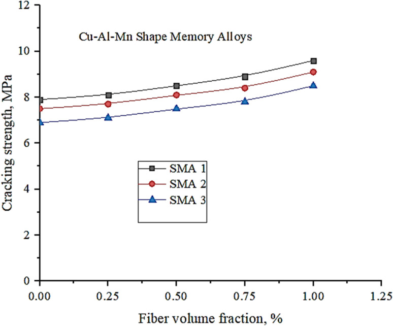
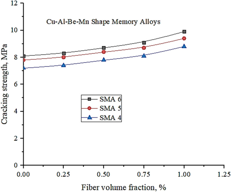
Fig. 11 and 12 shows the correlation between cracking strength and fibre volume %. During the course of the bending tests, the initial occurrence of cracking took place in the lower section of the beam, with these cracks gradually propagating upward within the beam structure. Following a gradual reduction of the applied load on the beam, measurements were taken to assess the width of the flexural crack at the lower part of the structure. This involved the precise measurement of the crack's dimensions at five different points along its length, using a magnifying glass.
Fig. 11. Variation of cracking strength with fibre volume fraction of Cu–Al–Mn SMA alloys.
Fig. 12. Variation of cracking strength with fibre volume fraction of Cu–Al–Be–Mn SMA alloys.
To address and seal the crack, a heating plate was employed. It was used to heat the SMA fibres inserted at the base of the beam to a temperature at least equal to the austenite finish temperature. The heating process continued until a thermocouple, attached to the central area of the beam's surface, reached the requisite temperature of 120 °C. Subsequently, post-cooling, the crack width was reevaluated to confirm that the closure had not led to any alteration in its dimensions.
As seen from Fig. 11, SMA 1 exhibited comparatively higher cracking strength due to improved ductility provided by Mn addition thereby decreasing the degree of order.23,24 Further as ductility increases, energy required for crack propagation increases and resistance for crack propagation enhances.
Similar trends are observed with Cu–Al–Be–Mn SMA alloys where SMA 6 showed higher cracking strength due to improved ductility provided by Mn and Be addition thereby decreasing the degree of order as depicted in Fig. 12. Cu–Al–Be–Mn SMA alloys showed higher cracking strength compared to Cu–Al–Mn.
3.4.4. Crack widths of SMA alloys
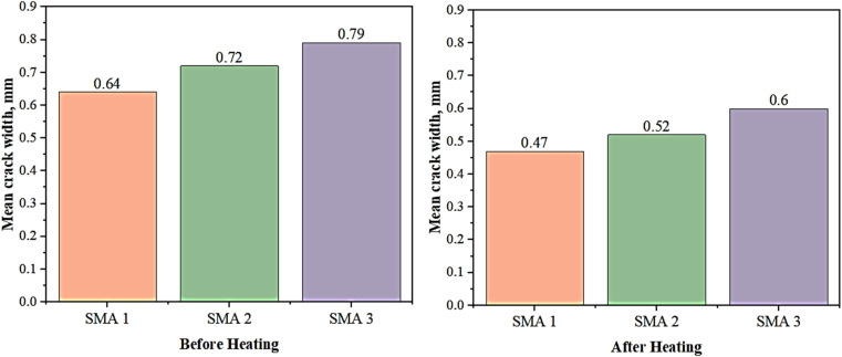
In Fig. 13, the measured crack widths are presented for both pre-heating and post-heating conditions. When compared to beams that lack tensile wires, the beams with embedded SMA fibres exhibit a more rapid reduction in crack width, indicating an enhanced capacity to close cracks. The effectiveness of crack closure in these beams improved by approximately 22–28% when the SMA fibre content on the underside subjected to tensile forces ranged between 0.5% and 1%. Furthermore, an increase in the number of SMA fibres on the tensile underside of the beam specimens with tensile wires was observed to lead to a further enhancement in crack-closing performance. Notably, SMA 1 demonstrated narrower cracks in comparison to other tested specimens, both before and after heating. Specifically, SMA 1 exhibited a reduction in crack width by 18.98% and 21.66% before and after heating, respectively, when compared to SMA 3.
Fig. 13. Variation of crack width for different SMAs.
3.4.5. XRD, DSC, SEM and EDAX of SMA's
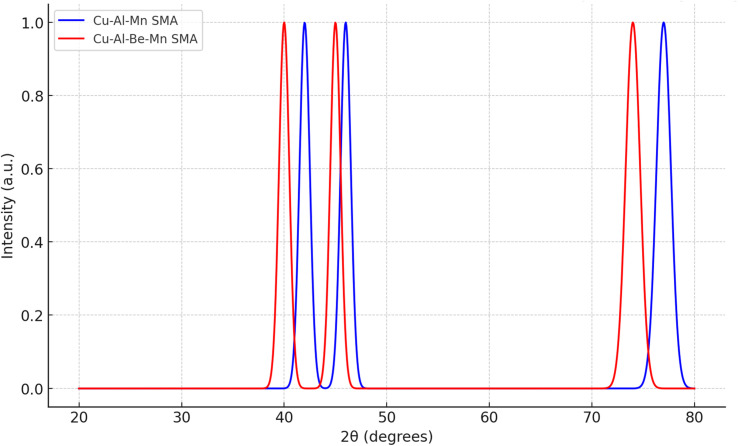
The characterization of Shape Memory Alloys (SMAs) often involves several techniques, each providing different insights into the material's structure, composition, and properties. X-ray Diffraction (XRD) is used to determine the crystalline structure of Shape Memory Alloys (SMAs) by identifying the phases present, such as austenite and martensite. It distinguishes between these phases through their unique diffraction patterns and provides information on lattice parameters based on the positions of XRD peaks. Additionally, XRD can be performed at different temperatures to observe phase transformations between austenite and martensite, which are essential for understanding the shape memory effect. The graph in Fig. 14 shows typical peaks associated with the β-phase and martensitic phase transitions in these materials.
Fig. 14. XRD graph of Cu–Al–Mn and Cu–Al–Be–Mn SMA's.
• Blue Line (Cu–Al–Mn SMA): Represents the XRD pattern for the Cu–Al–Mn alloy, with characteristic peaks that might correspond to the β-phase and martensitic phases.
• Red Line (Cu–Al–Be–Mn SMA): Represents the XRD pattern for the Cu–Al–Be–Mn alloy, showing similar phases with slight variations in peak positions due to the presence of Beryllium (Be).
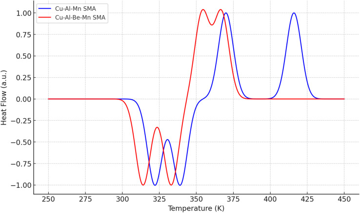
Differential Scanning Calorimetry (DSC) graph for the Cu–Al–Mn and Cu–Al–Be–Mn shape memory alloys is shown in Fig. 15. The graph shows the heat flow as a function of temperature:
Fig. 15. DSC graph of Cu–Al–Mn and Cu–Al–Be–Mn SMA's.
• Blue Line (Cu–Al–Mn SMA): Represents the DSC curve for the Cu–Al–Mn alloy. The exothermic peaks (negative heat flow) correspond to the martensitic transformation upon cooling, and the endothermic peaks (positive heat flow) correspond to the austenitic transformation upon heating.
• Red Line (Cu–Al–Be–Mn SMA): Represents the DSC curve for the Cu–Al–Be–Mn alloy. Similar to the Cu–Al–Mn alloy, the exothermic and endothermic peaks indicate the phase transformations between martensite and austenite.
In Shape Memory Alloys (SMAs), the β-phase and martensite phase are key structural phases influencing the material's properties. The β-phase, also known as austenite, typically has a body-centered cubic (BCC) or body-centered tetragonal (BCT) structure and is stable at high temperatures, allowing for shape recovery upon heating. In contrast, martensite forms at lower temperatures through a diffusionless transformation, characterized by a less symmetric, often monoclinic or orthorhombic structure. Martensite is harder and more brittle but can undergo reversible deformation, which is crucial for the shape memory effect.
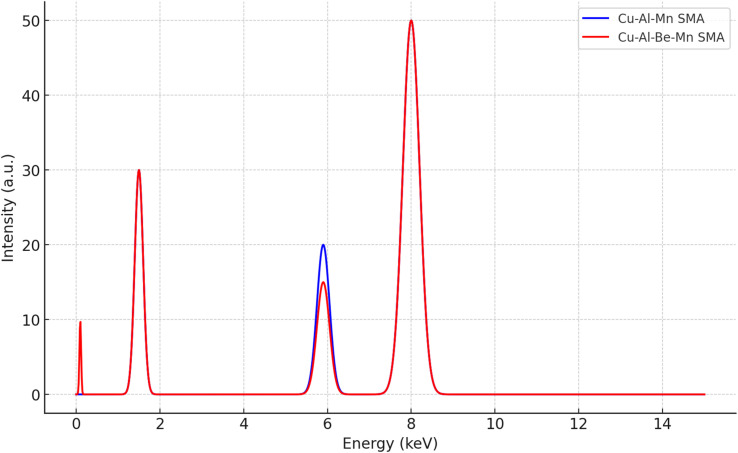
Using Energy Dispersive X-ray Spectroscopy (EDAX), these phases can be analyzed based on their elemental composition. EDAX can reveal the distribution of elements within the β-phase and martensite, helping to understand how alloying elements like Mn, Al, or Be influence phase stability and transformation behavior. This compositional analysis is essential for optimizing the mechanical properties and functionality of SMAs in various applications. The Fig. 16 gives the EDAX representation of the SMA's.
Fig. 16. EDAX graph of SMA's.
The Energy Dispersive X-ray Analysis (EDX or EDAX) spectrum for the Cu–Al–Mn and Cu–Al–Be–Mn shape memory alloys exhibits the following depictions:
• Blue Line (Cu–Al–Mn SMA): Shows the peaks corresponding to the presence of Copper (Cu), Aluminum (Al), and Manganese (Mn). The peak at around 8.0 keV represents the Cu K-alpha line, the peak at 1.5 keV corresponds to the Al K-alpha line, and the peak at 5.9 keV represents the Mn K-alpha line.
• Red Line (Cu–Al–Be–Mn SMA): In addition to the Cu, Al, and Mn peaks, there is a peak at a very low energy (∼0.1 keV) which represents the Beryllium (Be) K-alpha line, indicating the presence of Be in the alloy.
The EDAX spectrum also represents the elemental composition of the alloys, with the intensity of each peak corresponding to the relative concentration of the elements.
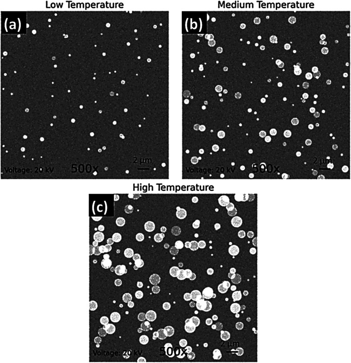
The SEM images of the Cu–Al–Be–Mn alloy at various temperatures reveal detailed microstructural features critical to understanding the material's properties as a Shape Memory Alloy (SMA). The images, captured at 500× magnification and 20 kV accelerating voltage, show distinct grain boundaries, phase distributions, and surface morphology.
At lower temperatures, the images suggest the presence of the martensitic phase, characterized by a more irregular grain structure, while higher temperatures likely reveal the smoother, more uniform β-phase (austenite). The contrast in the images may indicate different phases, with grain size and phase distribution influenced by temperature. Surface features such as ridges and potential defects like cracks or inclusions are also visible, providing insights into the alloy's deformation mechanisms and overall mechanical properties.
These observations are crucial for optimizing the alloy's composition and processing conditions to enhance properties like superelasticity, fatigue resistance, and thermal stability. The scale marker of 2 μm helps quantify these microstructural characteristics, making the SEM images a valuable tool in the study and application of SMAs.
Fig. 17a–c likely depict the microstructural evolution of the Cu–Al–Be–Mn alloy at low, medium, and high temperatures, respectively.
Fig. 17. SE micrograph of microstructural evolution at (a) low, (b) medium and (c) high temperature of Cu–Al–Be–Mn based SMA.
In Fig. 17a, the SEM image at low temperature shows a well-defined grain structure, possibly highlighting the martensitic phase. The grain boundaries are clear, indicating the stability of this phase at lower temperatures, with potential evidence of phase transformation beginning to occur.
Fig. 17b, captured at medium temperature, reveals more complex microstructural features. The image likely shows the coexistence of martensite and austenite phases, with noticeable changes in contrast. This suggests ongoing phase transformation, with the material exhibiting mixed-phase characteristics that contribute to its shape memory properties.
In Fig. 17c, taken at high temperature, the SEM image shows a more uniform and smoother microstructure, characteristic of the β-phase (austenite). The grain boundaries may appear less distinct, and the overall morphology reflects the material's high-temperature stability, with the β-phase dominating the microstructure.
These images together illustrate the temperature-dependent phase transformations in the alloy, crucial for understanding its behaviour and optimizing its shape memory and super elastic properties.
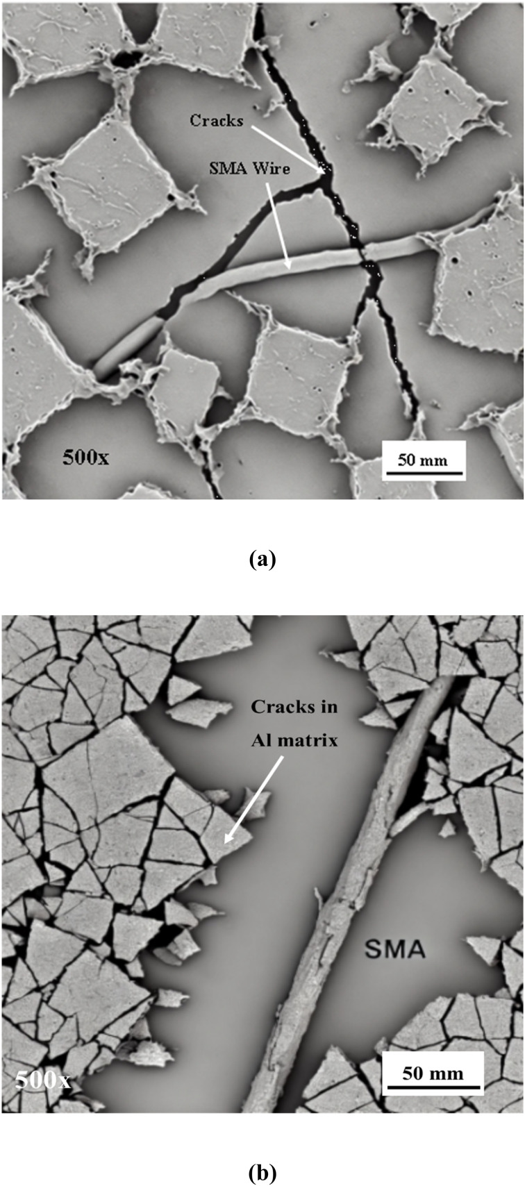
Fig. 18 depicts SEM images of Cu–Al–Mn and Cu–Al–Be–Mn-based Shape Memory Alloys (SMAs) embedded within an aluminum matrix, highlighting the microstructural differences and the crack propagation behavior when subjected to mechanical transformations.
Fig. 18. SEM image of (a) Cu–Al–Mn and (b) Cu–Al–Be–Mn based SMA's in Al matrix and the crack propogration in the Al matrix when subjected to different mechanical transformations.
• (a) Cu–Al–Mn in Al matrix: This SEM image shows the microstructure of a Cu–Al–Mn-based SMA embedded in the aluminum matrix. The SMA particles or fibers are distributed within the matrix, and the contrast difference highlights the interface between the SMA and the aluminum. The image may reveal how cracks propagate through the matrix, potentially deflecting at the SMA reinforcements, which can impact the material's toughness and resistance to crack growth.
• (b) Cu–Al–Be–Mn in Al matrix: The second SEM image focuses on a Cu–Al–Be–Mn-based SMA within the aluminum matrix. The presence of Beryllium (Be) alters the microstructure, which may be visible in the SEM as changes in grain size or phase distribution. The image likely shows how the introduction of Be influences crack propagation, possibly enhancing the crack deflection mechanism or changing the nature of the cracks observed.
• In both images: The SEM images illustrate how cracks initiate and propagate within the aluminum matrix. The cracks might interact with the embedded SMA particles, either deflecting around them or being arrested by them, depending on the bonding quality and the phase distribution. This interaction is crucial for understanding the mechanical properties, particularly the alloy's resistance to fatigue and fracture under different mechanical loads.
These images provide insight into how different alloying elements (Mn and Be) affect the microstructure and crack behavior in aluminum matrix composites, contributing to the overall performance and durability of the material.
4. Conclusions
This study focuses on chemical composition, transformation temperatures, SME and SE of Cu–Al–Mn and Cu–Al–Be–Mn SMAs respectively. Among the Cu–Al–Mn SMAs, the SMA1 showed higher strain recovery which increased by 6.74% and 5.55% compared to SMA 2 and SMA3 respectively. While among the Cu–Al–Be–Mn SMAs, the SMA6 showed higher strain recovery which increased by 45.45% and 9.1% compared to SMA 4 and SMA5 respectively.
Further the mechanical properties of Cu–Al–Mn and Cu–Al–Be–Mn SMAs based Al MMC composites with varied percentage of SMA fibres are investigated.
The composite pour was only applied to the underside of the beam samples, a location more susceptible to cracking. The utilization of SMA fibre-infused composites was tested for their potential to seal fissures and impact the flexural tensile strength of the beams. During the four-point bending tests, the control beams exhibited a rapid decline in load resistance and a sudden, brittle failure. In contrast, the beams embedded with SMA fibres maintained load resistance even after experiencing cracks. As a result of the bending tests, the bottom side of the beams displayed permanent flexural cracks. To address this, the Shape Memory Effect (SME) of the SMA fibres positioned on the lower side of the beam was activated by heating, successfully closing the flexural cracks. Furthermore, it was observed that an increase in the quantity of SMA fibre on the tensile bottom side enhanced the crack-closure performance of the beam samples with tensile wires. However, the beams with tensile wires exhibited a moderate and consistent crack-closure ability, regardless of the specific types of SMA fibres employed.
Among the different SMAs synthesized, SMA1 (Cu-80.94, Al-10.54 and Mn-8.52) exhibited improved martensite stability and SE compared to SMA2 and SMA3 respectively. SMA 1 showed higher residual strength, cracking strength and energy absorption capacity compared to other selected coupons. At 1%, fibre volume fractions, SMA 1 showed higher residual strength (11.28%), energy absorption capacity (22.72%), cracking strength (12.94%), and lower crack widths (21.66%) compared to SMA 3 infused composite.
While among the Cu–Al–Be–Mn SMAs, the SMA6 (Cu-87.42, Al-11.8, Be-0.48 and Mn-0.3) exhibited improved martensite stability and SE compared to SMA4 and SMA5 respectively. SMA 6 showed higher residual strength, cracking strength and energy absorption capacity compared to other selected coupons. At 1%, fibre volume fractions, SMA 6 showed higher residual strength (8.63%), energy absorption capacity (55%), and cracking strength (12.50%) compared to SMA 4 infused composite. Cu–Al–Be–Mn SMAs showed good mechanical properties compared to Cu–Al– Mn SMAs.
Data availability
The dataset supporting the research is incorporated in the manuscript itself. However, additional data supporting the findings will be furnished upon request to the corresponding authors.
Conflicts of interest
Authors declare no conflict of interest.
Acknowledgments
The authors extend their appreciation to the Deanship of Research and Graduate Studies at King Khalid University for funding this work through Large Research Project under grant number RGP2/40/45.
References
- Jani J. M. Leary M. Subic A. Gibson M. A. A review of shape memory alloy research, applications and opportunities. Mater. Des. 2014;56:1078–1113. doi: 10.1016/j.matdes.2013.11.084. doi: 10.1016/j.matdes.2013.11.084. [DOI] [Google Scholar]
- Torra V. Martorell F. Lovey F. C. Sade M. L. Civil engineering applications: specific properties of NiTi thick wires and their damping capabilities, a review. Shape Mem. Superelasticity. 2017;3:403–413. doi: 10.1007/s40830-017-0135-y. [DOI] [Google Scholar]
- Oliveira J. P. Barbosa D. Fernandes F. B. Miranda R. M. Tungsten inert gas (TIG) welding of Ni-rich NiTi plates: functional behavior. Smart Mater. Struct. 2016;25(3):03LT01. doi: 10.1088/0964-1726/25/3/03LT01. [DOI] [Google Scholar]
- Oliveira J. P. Duarte J. F. Inácio P. Schell N. Miranda R. M. Santos T. G. Production of Al/NiTi composites by friction stir welding assisted by electrical current. Mater. Des. 2017;113:311–318. doi: 10.1016/j.matdes.2016.10.038. [DOI] [Google Scholar]
- Lecce L. and Concilio A., Shape Memory Alloy Engineering, Butterworth-Heinemann, 1st edn, 2014, https://www.sciencedirect.com/science/book/9780080999203 [Google Scholar]
- Gao S. Yi S. Experimental study on the anisotropic behavior of textured NiTi pseudoelastic shape memory alloys. Mater. Sci. Eng. A. 2003;362:107–111. doi: 10.1016/S0921-5093(03)00585-9. doi: 10.1016/S0921-5093(03)00585-9. [DOI] [Google Scholar]
- Wang W. Fang C. Yang X. Chen Y. Ricles J. Sause R. Innovative use of a shape memory alloy ring spring system for self-centering connections. Eng. Struct. 2017;153:503–515. doi: 10.1016/j.engstruct.2017.10.039. [DOI] [Google Scholar]
- Lu X. Zhang L. Lin K. Li Y. Improvement to composite frame systems for seismic and progressive collapse resistance. Eng. Struct. 2019;186:227–242. doi: 10.1016/j.engstruct.2019.02.006. [DOI] [Google Scholar]
- Li R. Ge H. Usami T. Shu G. A strain-based post-earthquake serviceability verification method for steel frame-typed bridge piers installed with seismic dampers. J. Earthq. Eng. 2017;21:635–651. doi: 10.1080/13632469.2016.1157531. [DOI] [Google Scholar]
- Dolce M. Cardone D. Mechanical behaviour of shape memory alloys elements for seismic applications: Part 1—martensite and austenite NiTi bars subjected to torsion. Int. J. Mech. Sci. 2001;43:2631–2656. doi: 10.1016/S0020-7403(01)00049-2. [DOI] [Google Scholar]
- Dolce M. Cardone D. Mechanical behaviour of shape memory alloys for seismic applications Austenite NiTi wires subjected to tension. Int. J. Mech. Sci. 2001;43:2657–2677. doi: 10.1016/S0020-7403(01)00050-9. [DOI] [Google Scholar]
- Mekki O. B. Auricchio F. Performance evaluation of shape-memory-alloy superelastic behavior to control a stay cable in cable-stayed bridges. Int. J. Non-Linear Mech. 2011;46:470–477. doi: 10.1016/j.ijnonlinmec.2010.12.002. [DOI] [Google Scholar]
- Torra V. Isalgue A. Auguet C. Carreras G. Lovey F. C. Terriault P. Dieng L. SMA in mitigation of extreme loads in civil engineering: damping actions in stayed cables. Appl. Mech. Mater. 2011;82:539–544. [Google Scholar]
- Zhang Y. Zhu S. Seismic response control of building structures with superelastic shape memory alloy wire dampers. J. Eng. Mech. 2008;134:240–251. doi: 10.1061/(ASCE)0733-9399(2008)134:3(240). [DOI] [Google Scholar]
- Dieng L. Helbert G. Chirani S. A. Lecompte T. Pilvin P. Use of shape memory alloys damper device to mitigate vibration amplitudes of bridge cables. Eng. Struct. 2013;56:1547–1556. doi: 10.1016/j.engstruct.2013.07.018. [DOI] [Google Scholar]
- Massah S. R. Dorvar H. Design and analysis of eccentrically braced steel frames with vertical links using shape memory alloys. Smart Mater. Struct. 2014;23:115015. doi: 10.1088/0964-1726/23/11/115015. [DOI] [Google Scholar]
- Yang C. S. W. DesRoches R. Leon R. T. Design and analysis of braced frames with shape memory alloy and energy-absorbing hybrid devices. Eng. Struct. 2010;32:498–507. doi: 10.1016/j.engstruct.2009.10.011. [DOI] [Google Scholar]
- DesRoches R. Smith B. Shape memory alloys in seismic resistant design and retrofit: a critical review of their potential and limitations. J. Earthq. Eng. 2004;8:415–429. [Google Scholar]
- Wang Z. Xu L. Sun X. Shi M. Liu J. Fatigue behavior of glass-fibre-reinforced epoxy composites embedded with shape memory alloy wires. Compos. Struct. 2017;178:311–319. doi: 10.1016/j.compstruct.2017.07.027. [DOI] [Google Scholar]
- Gholampour A. Ozbakkaloglu T. Understanding the compressive behavior of shape memory alloy (SMA)-confined normal-and high-strength concrete. Compos. Struct. 2018;202:943–953. doi: 10.1016/j.compstruct.2018.05.008. [DOI] [Google Scholar]
- Pareek S. Suzuki Y. Araki Y. Youssef M. A. Meshaly M. Plastic hinge relocation in reinforced concrete beams using Cu-Al-Mn SMA bars. Eng. Struct. 2018;175:765–775. doi: 10.1016/j.engstruct.2018.08.072. [DOI] [Google Scholar]
- Abdulridha A. Palermo D. Behaviour and modelling of hybrid SMA-steel reinforced concrete slender shear wall. Eng. Struct. 2017;147:77–89. doi: 10.1016/j.engstruct.2017.04.058. [DOI] [Google Scholar]
- Branco M. Gonçalves A. Guerreiro L. Ferreira J. Cyclic behavior of composite timber-masonry wall in quasi-dynamic conditions reinforced with superelastic damper. Constr. Build. Mater. 2014;52:166–176. doi: 10.1016/j.conbuildmat.2013.10.095. [DOI] [Google Scholar]
- Shahverdi M. Michels J. Czaderski C. Motavalli M. Iron-based shape memory alloy strips for strengthening RC members: Material behavior and characterization. Constr. Build. Mater. 2018;173:586–599. doi: 10.1016/j.conbuildmat.2018.04.057. [DOI] [Google Scholar]
- Kainuma R. Satoh N. Liu X. J. Ohnuma I. Ishida K. Phase equilibria and Heusler phase stability in the Cu-rich portion of the Cu–Al–Mn system. J. Alloys Compd. 1998;266:191–200. doi: 10.1016/S0925-8388(97)00425-8. [DOI] [Google Scholar]
- Sutou Y. Kainuma R. Ishida K. Effect of alloying elements on the shape memory properties of ductile Cu–Al–Mn alloys. Mater. Sci. Eng. A. 1999;273:375–379. doi: 10.1016/S0921-5093(99)00301-9. [DOI] [Google Scholar]
- Lara-Rodriguez G. A. Gonzalez G. Flores-Zuniga H. Cortes-Perez J. The effect of rapid solidification and grain size on the transformation temperatures of Cu-Al-Be melt spun alloys. Mater. Charact. 2006;57:154–159. doi: 10.1016/j.matchar.2005.12.017. [DOI] [Google Scholar]
- Candido G. V. D. M. Melo T. A. D. A. Albuquerque V. H. C. Gomes R. M. Lima S. J. G. Tavares J. M. R. S. Characterization of a CuAlBe alloy with different Cr contents. J. Mater. Eng. Perform. 2012;21:2398–2406. doi: 10.1007/s11665-012-0159-6. doi: 10.1007/s11665-012-0159-6. [DOI] [Google Scholar]
- Gowda N. R. Yellappa K. S. S. Manchalakar A. Kumar U. L. Santhosh N. Study of tribological characteristics of NiTiFe shape memory alloys for varying composition of Fe. Int. j. adv. res. innov. 2015;4(6):170–174. [Google Scholar]
- Higuchi A. Suzuki K. Matsumoto Y. Sugimoto K. Komatsu S. Nakamura Y. Shape memory effect in Cu-Al-Be ternary alloys. J. Phys., Colloq. 1982;43:C4-767–C4-772. doi: 10.1051/jphyscol:19824125. [DOI] [Google Scholar]
- Oliveira J. P. Panton B. Zeng Z. Omori T. Zhou Y. Miranda R. M. Fernandes F. B. Laser welded superelastic Cu–Al–Mn shape memory alloy wires. Mater. Des. 2016;90:122–128. doi: 10.1016/j.matdes.2015.10.125. [DOI] [Google Scholar]
- Oliveira J. P. Zeng Z. Omori T. Zhou N. Miranda R. M. Fernandes F. B. Improvement of damping properties in laser processed superelastic Cu-Al-Mn shape memory alloys. Mater. Des. 2016;98:280–284. doi: 10.1016/j.matdes.2016.03.032. [DOI] [Google Scholar]
- Oliveira J. P. Zeng Z. Berveiller S. Bouscaud D. Fernandes F. B. Miranda R. M. Zhou N. Laser welding of Cu-Al-Be shape memory alloys: Microstructure and mechanical properties. Mater. Des. 2018;148:145–152. doi: 10.1016/j.matdes.2018.03.066. [DOI] [Google Scholar]
- Babu K. N. Biradar M. Udupa N. G. S. Naik R. M. Santhosh N. Characteristic evaluation of wear properties of NiTiAl based shape memory alloys for different composition. Int. J. Adv. Innov. Res. 2015;3(10):342–346. [Google Scholar]
- Santhosh N. Reddy V. Aswatha S. K. N. Sureshkumar S. Manchalakar A. Kumar U. L. Experimental and analytical studies on mechanical properties of Nitinol based shape memory alloys for biomedical application. Int. j. adv. res. innov. 2015;4(8):33–39. [Google Scholar]
Associated Data
This section collects any data citations, data availability statements, or supplementary materials included in this article.
Data Availability Statement
The dataset supporting the research is incorporated in the manuscript itself. However, additional data supporting the findings will be furnished upon request to the corresponding authors.


