Abstract
Gold nanorods (GNRs) are one of the most promising biomaterial choices for the photothermal activation of neurons due to their relative biocompatibility, unique photothermal properties, and broad optical tunability through their synthetic shape control. While photothermal stimulation using randomly accumulated GNRs successfully demonstrates the potential treatment of functional neural disorders by modulating the neuronal activities using localized heating, there are limited demonstrations to translate this new concept into large-arrayed neural stimulations. In this paper, we report an arrayed PDMS micropillar platform in which GNRs are embedded as pixel-like, arrayed photothermal stimulators at the tips of the pillars. The proposed platform will be able to localize GNRs at predetermined pillar positions and create thermal stimulations using near-infrared (NIR) light. This will address the limitations of randomly distributed GNR-based approaches. Furthermore, a flexible PDMS pillar structure will create intimate interfaces on target cells. By characterizing the spatiotemporal temperature change in the platform with rhodamine B dye, we have shown that the localized temperature can be optically modulated within 4°C, which is in the range of temperature variation required for neuromodulation using NIR light. We envision that our proposed platform has the potential to be applied as a photothermal, neuronal stimulation interface with high spatiotemporal resolution.
Keywords: Photothermal stimulation, soft lithography, gold nanorod, PDMS micropillar array, near-infrared actuation
I. INTRODUCTION
GOLD nanorods (GNRs) have gained significant attention from the scientific community over the last few decades owing to their unique electrical and optical properties [1], [2]. Easy-to-tune size and shape, biocompatibility, and surface functioning have made GNR tremendously useful in biological applications [3]. Studies have reported its potential in numerous applications such as sensing [4], imaging [5], tracking [6], and drug delivery [6], [7]. Moreover, the photothermal property of GNR has numerous implications in medicinal science [8]. In this case, the coupling of the electromagnetic wave of light and the surface electron cloud gives rise to the collective oscillation of electrons. The frequency of the collision of these conduction electrons with the lattice atoms results in joule heating [8]. The shape of GNR can be tuned to respond to the photothermal effect under Near-infrared (NIR) light illumination. Since NIR light can penetrate deeply inside human tissue [9], GNR is one of the ideal nanomaterials that can be remotely actuated inside the human body. In cancer photothermal therapy (PTT), GNR is modified to gather near the tumor tissue followed by irradiation with NIR light. Thus, the generated heat can kill the cancer cells under the hyperthermal environment [10].
Despite significant progress, the application of the photothermal property of GNR has been mostly limited to PTT in cancer cells and remote-controlled drug delivery. In photothermal stimulation, localized heat produced near neurons can change the capacitance of their membrane and activate temperature-gated ion channels to stimulate neurons [11]. This approach has gained attraction due to its relative non-invasiveness and spatiotemporal accuracy compared to traditional electrical stimulation [12]. Using GNRs injected locally into a prepared sciatic nerve, Mou et al. have shown optical stimulation of muscle action potential [13]. To illustrate the laser-induced electrical activity of neurons, whole-cell patch-clamp electrical recording at a single cell level was also performed with simultaneous laser stimulation via an optical fiber [14]. Yoo et al. have also demonstrated that the photothermal property of GNR can modulate neural activities by incubating GNRs with isolated neuronal cells [15]. This approach shows the possibility of inhibiting neural activity by raising the temperature from 1.5-8°C by applying an NIR pulse. A similar effort has been demonstrated by attaching GNR to an optical fiber tip where temperature increases up to 3.5-4°C with a 30s laser pulse [16]. Though it is a noteworthy development to confirm the potential of GNR in neuromodulation, the lack of flexibility of fiber optics hinders it from being used in clinical use [17]. Another drawback of GNR embedded on a fiber tip platform is that it can only stimulate one region at a time.
While current approaches of photothermal stimulation successfully demonstrate the potential treatment of functional neural disorders by modulating the neuronal activities using localized heating, there are limited demonstrations to translate this new concept into large-arrayed neural stimulation such as a retinal prosthesis. In this work, we present a two-dimensional PDMS micropillar array with GNR-embedded pillar tip that functions as photothermal pixels. The thermal stimulation of these pixels is independently controlled by light and highly localized, without the need for physical wires. Based on microfabrication and soft-molding techniques, GNR-embedded pillars are small enough to be interfaced with single-cell stimulation, and the PDMS structure is flexible and scalable to a large array for high-resolution stimulation. The two-dimensional, predetermined location of photothermal pixels addresses the random distribution of GNR in the many demonstrations of photothermal neural stimulations [14], [15], [18]. Furthermore, flexible PDMS micropillar can form intimate interfaces with target neurons, compared to the planar gold-nano patterns [19]. The temperature resulting from each pillar can be individually modulated with NIR laser illumination with high spatiotemporal resolution. To create this unique structure, we devise soft lithography processes combining different molding materials. The detailed fabrication procedure will be discussed in the experimental section. The temperature characterization of the proposed platform will be presented with temperature-sensitive dye. The measured results present that the proposed structure has the potential to realize a high-resolution spatiotemporal photothermal stimulation interface, satisfying the necessary temperature change for neuromodulation.
II. Experiment
A. Materials
Silver Nitrate (AgNO3) was purchased from TGI America. Ascorbic acid (C6H8O6), Polyvinyl Alcohol (PVA), Perfluorodecyltrichlorosilane (FDTS), and Rhodamine B were purchased from VWR. Chloroauric acid (HAuCl4), Sodium borohydride (NaBH4), Tetraethyl orthosilicate (TEOS), and Hexadecyltrimethylammonium bromide (CTAB) were purchased from Sigma Aldrich. AZ BARLi II, AZ P4620 photoresist, and AZ-400k developer were obtained from AZ Electronic Materials. All chemicals were used as received.
B. Preparation of GNR
GNR was synthesized following the previously discussed seed-mediated method [20], [21]. Briefly, seed solution was prepared by stirring 600 μL of ice-cold NaBH4 (10 mM) with the mixture of 250 μL of HAuCl4 (10 mM) solution in 9.75 mL of CTAB (0.1 M) vigorously at 28°C for 10 min. Then the seed solution was left undisturbed for 1 hr at 28°C. Meanwhile, the growth solution was prepared by mixing 95 μL of AgNO3 (10 mM) with CTAB (0.1 M) gently followed by the addition of 500 μL of HAuCl4 (10 mM). Then, 55 μL of C6H8O6 (0.1 M) was added to the growth solution. The growth solution turned colorless at this point from a light pink color. Lastly, 12 μL of seed solution was injected slowly into the growth solution. GNR with desirable absorption peak was ready after keeping the solution undisturbed at 28°C for 1 hr. To obtain GNR with the desirable absorption peak, AgNO3 amount needs to be varied in the growth solution. The as-synthesized GNR was centrifuged at 10,000 rpm and the supernatant was replaced with DI water twice.
C. Preparation of Silica-Coated GNR (Si-GNR)
10 μL of NaOH (0.1 M) was mixed with GNR solution at 1000 rpm for 10 min. Then, the stirring speed of the magnetic stirrer was adjusted to 240 rpm, and 12 μL of 20% (v/v) of TEOS in methanol was added dropwise three times with an interval of 30 min. After overnight stirring, the solution was centrifuged, and the supernatant was replaced with ethanol as a washing cycle.
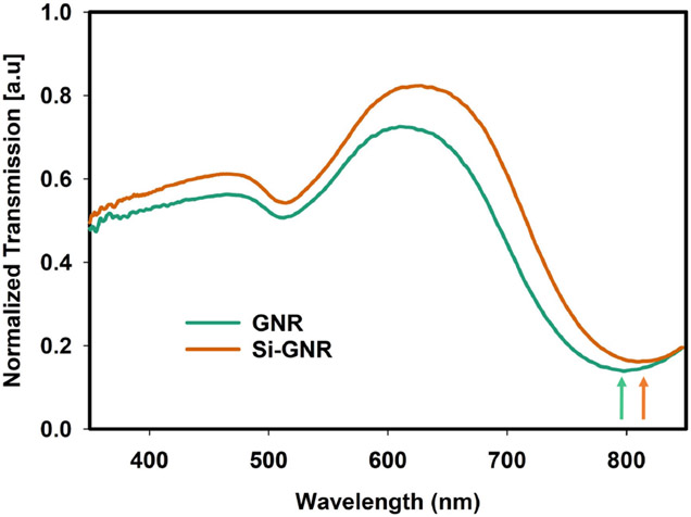
The normalized UV-Vis transmission spectra of GNR and silica-coated GNR in water are shown in Fig. 1. There are two absorption peaks of GNR. Longitudinal localized surface plasmon resonance (LSPR) causes an absorption peak at ~810 nm and Latitudinal LSPR causes peak around ~510 nm. Since the transmission dip of GNR suspended in water is around 800 nm, it will absorb most of the NIR light illuminated in that wavelength range and convert it to heat. The redshift of UV-Vis transmission spectra dip of silica-coated GNR in water (from ~795 nm to ~810 nm) compared to GNR confirms the silica coating of GNR. As reported in several studies, the transmission dip is slightly redshifted because the refractive index of silica (SiO2) is higher than water [22], [23]. The slight variation in the amplitude of normalized transmission of GNR and silica-coated GNR in Fig. 1 is due to a slight variation in nanorod concentration lost during the cleaning cycle. We have used silica-coated GNR in all the experiments discussed in this study.
Fig. 1.
Normalized UV-Vis transmission spectra of GNR and silica–coated GNR.
D. Fabrication of GNR-Embedded PDMS Micropillar Array
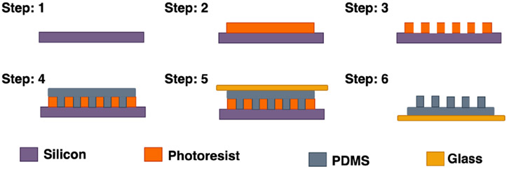
PDMS micropillar array mold was fabricated using the soft lithography technique. Fig. 2 illustrates the steps involving the fabrication of PDMS micropillar array. To prepare the mold, a silicon substrate of 675 μm thickness with 100 nm thick SiO2 layer was spin-coated with AZ BARLi 90 at 2500 rpm for 40 s followed by baking for 2 min at 200°C (steps 1 & 2). Then, AZ P4620 was spin coated at 1200 rpm for 40 s and baked at 110°C for 4 min. After removing the edge beads the samples were baked again for 1 min at 110°C. Then the samples were exposed to UV light for 870 mJ using a mask aligner (Karl Suss, MJB 3) and developed in AZ-400k developer (1:4 diluted in DI water) (step 3). The photoresist thickness, measured with a surface profilometer (Veeco, Dektak 150), is around 16μm. Next, the molds were treated hydrophobic using FDTS vapor treatment. To obtain the micropillar array, PDMS precursor solution (10:1 monomer to curing agent) was poured on the mold and degassed thoroughly using a desiccator to remove air bubbles (step 4). In the meantime, a microscope glass slide was cleaned with solvents (acetone, methanol, and isopropyl alcohol) and oxygen plasma treated for 1 min (Oxygen flow rate at 20 sccm, 100W RF power). Then the glass slide was placed on the desiccated PDMS (step 5). After curing for 4 hrs at 60°C, the PDMS micropillar array was obtained when the microscope glass slide is detached from the photoresist mold (step 6).
Fig. 2.
Schematic diagram of fabrication steps of PDMS micropillar array.
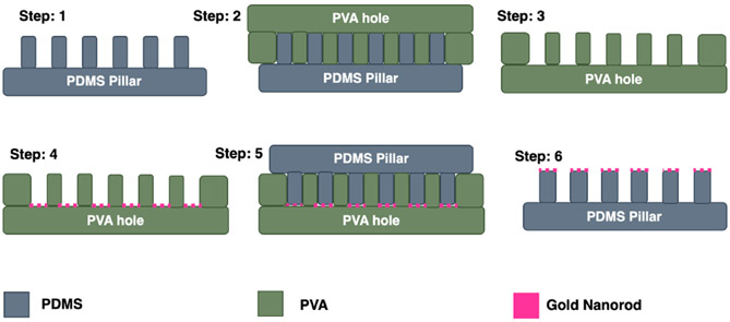
Fig. 3 shows the fabrication process of GNR embedded on the tip of the PDMS micropillar array. Firstly, 5% PVA solution was dropped on PDMS micropillar and left to spread evenly (steps 1 & 2). Any bubble was removed through desiccation and baked on a hotplate at 120°C for 10 min. Then the PDMS micropillar with PVA was oxygen plasma treated for 30 s. NOA 76 UV curable resin was then dropped over the PVA and left to spread evenly. Next, an oxygen plasma-treated glass slide was placed on top of it and cured under UV light for 15 min. The glass slide with PVA ‘inverted pillar’ structure was then detached from the PDMS micropillar gently (step 3). Silica-coated GNR suspended in ethanol was then poured on the PVA inverted pillar structure and scraped with a PDMS block to fill up the pores with GNR suspension. When ethanol evaporated, the PVA structure was gently scraped with a razor blade to remove GNR from the top surface (step 4). Then PDMS precursor (10:1 monomer to curing agent) was poured on it and desiccated thoroughly to remove any air bubbles (step 5). An oxygen plasma-treated glass substrate was then placed on PDMS and left to cure for 4 hrs at 60°C. The PDMS micropillar picked up the GNR along with it when it was detached from the PVA structure (step 6). The sample was then baked at 150°C for 30 min to strengthen the physical bonding.
Fig. 3.
Schematic diagram of fabrication steps of GNR-embedded tips of PDMS micropillar array.
Fig. 4 shows the scanning electron microscope (SEM) images of the samples taken at different steps of the fabrication process. Fig. 4(a) shows the PDMS micropillar array prepared from the soft lithography technique. Fig. 4(b) and Fig.4(c) show the PVA inverted pillar structure and the PDMS micropillar prepared from it. Thus, the geometric features of Fig. 4(a) and Fig. 4(c) are similar. Although the dimensions of the PDMS pillar (5 μm in tip diameter and 12 μm of pitch distance) were selected for microscopic characterizations, they can be adjusted further to effectively interface with target cells using the microfabrication techniques presented in the paper. It is well known that localized temperature changes have the ability to activate temperature-sensitive ion channels, which are located around cell membranes [18], [24], [25], [26]. In a practical application, the dimension of the proposed pillar array should be optimized to provide effective thermal pixels for a single cell-level actuation to maximize its spatial resolution.
Fig. 4.
Scanning electron microscope images of (a) PDMS micropillar (b) PVA inverted pillar and (c) PDMS micropillar made from the PVA inverted pillar structure. The scale bar is 100 μm.
III. Result and Discussion
A. Characterization of GNR-Embedded Tip of PDMS Micropillar Array
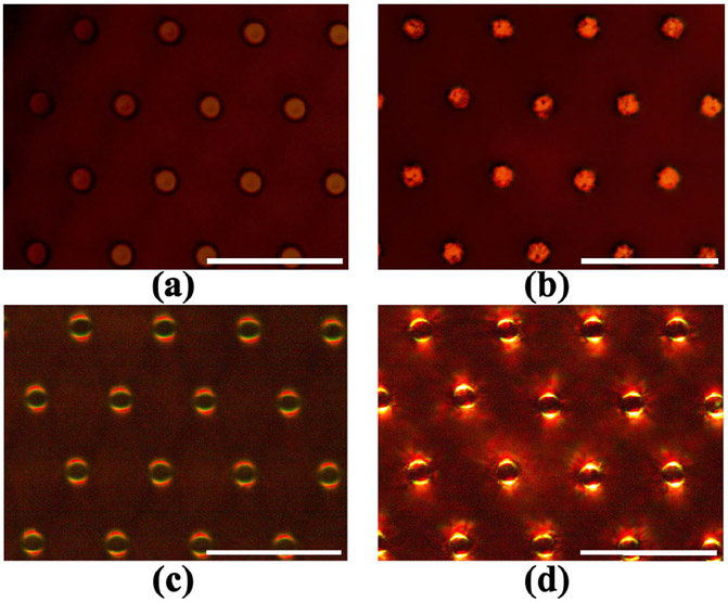
First, we have confirmed the GNR on the tip of the PDMS micropillar by observing the sample with an optical microscope (Nikon, Eclipse L200). Densely packed GNR on the tip of the PDMS micropillar can be spotted under high magnification. Fig. 5 shows an optical microscope image of the tip of the PDMS micropillar array with and without GNR. Fig. 5(a) shows the PDMS pillar has a smooth tip surface compared to the PDMS tip embedded with GNR as shown in Fig. 5(b). Since there is no GNR in Fig. 5(a), the tips are much more uniform in color compared to the tips of the micropillar array in Fig. 5(b). Scattering of light by metal nanoparticles can be visualized using dark-field microscopy [3]. Dark-field microscopy image provides more evidence of GNR embedded on the tip of the micropillar array. Scattering of light along the edges of the micropillar tip is much more prominent when GNR is present as shown in Fig. 5(c) and (d). As GNR is deposited on the tip, the surface becomes rougher and thus scatter more light.
Fig. 5.
Optical microscope image of PDMS micropillar tip. Bright-field microscope image (a) without GNR and (b) with GNR. Dark-field microscope image (c) without GNR and (d) with GNR. The scale bar is 20 μm.
Furthermore, we have confirmed the presence of GNRs in the PDMS micropillar array by measuring the optical spectral response through the sample. For this measurement, the sample was placed under an inverted microscope (Leica DMIL), and the eyepiece of the microscope was connected with a UV-Vis spectrometer through a fiber optics cable. The light above the microscope stage acted as the illumination source for the UV-Vis spectroscopy measurement. The illuminated light was calibrated without the sample and then, the optical transmission through the sample was measured. A schematic diagram of the experimental setup is illustrated in Fig. 6(a). Fig. 6(b) shows the image of the sample area corresponding to the spectrum measurement. The UV-Vis Spectra in Fig. 6(c) shows that the absorption peaks from GNRs still remained without degradation in our device structure after our embedding processes. The longitudinal and latitudinal peaks do not shift significantly compared to GNR suspension in water. Silica-coating introduces a physical barrier between GNR cores which can effectively solve the issue of the aggregation of bare GNRs during their evaporation-induced assembly, which results in the reduced absorption peaks seen in other demonstrations [14], [27].
Fig. 6.
UV-Vis Spectrum of GNR embedded on the PDMS micropillar array. (a) Experimental setup. (b) Region of the sample where the spectrum is measured. (c) Corresponding UV-Vis spectra measured of the region in (b). The scale bar is 50 μm.
B. Temperature Measurement With Rhodamine B Dye
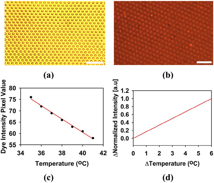
The temperature characteristics of the sample has been analyzed both spatially and temporally using the temperature dependent fluorescence feature of rhodamine B dye, which has a green excitation at λ = 532nm and an emission above λ = 590nm. 1 wt.% of rhodamine B dye was added with acetone and mixed thoroughly. Then, the PDMS micropillar array with GNR was soaked in the dye solution overnight. Since PDMS is permeable to acetone, rhodamine B dye will be absorbed inside the PDMS. The sample was then rinsed with DI water and baked at 100°C for 10 min for drying. Fig. 7(a) shows the image of the sample under white light illumination through an optical microscope and Fig. 7(b) shows the fluorescent emission image of the sample soaked in rhodamine B dye under green excitation illumination. The emission intensity of the tip of the micropillar in Fig. 7(b) appears to be higher than the base area as more rhodamine B molecule is accumulated in that region. It is well understood that the emission intensity of the rhodamine B dye decreases as temperature increases [28].
Fig. 7.
(a) Optical microscope image of the PDMS micropillar array under white light. (b) Optical microscope image (emission) of the sample soaked in rhodamine B dye under green light (excitation). (c) rhodamine B dye emission intensity with varying temperatures. (d) Normalized function of change of emission intensity with change of temperature. The scale bar is 50 μm.
The sample was first placed on a temperature-controlled aluminum stage and the temperature of the stage was fixed to 35°C. The emission intensity of the region of interest was recorded from 35°C to 41°C. Between each data point, there was 5 min wait period to allow the dye to completely response to the corresponding temperature change. Measurement for each set point was taken 3 times, and the average was calculated. Fig. 7(c) shows the emission intensity pixel values of the dye corresponding to different temperatures. The change in emission intensity and temperature in this study was under this range as shown in Fig. 7(c). The normalized emission intensity change (Δ Intensity) of the dye with the change of temperature (Δ Temperature) has been calculated from Fig. 7(c). This plot is illustrated in Fig. 7(d) which served as the calibration curve for change in emission intensity of the dye over temperature. Temperature change has been estimated following the change in emission intensity value.
C. Localized Photothermal Response Characterization
In order to generate heat in the fabricated sample through GNR-enabled photothermal process, NIR laser beam was illuminated via a microscope objective lens. The illuminated NIR laser power through the objective lens was first measured by an optical power meter with a calibrated detector (Newport 1930C and 918-SL-OD1R). By measuring the NIR illumination area from microscopic images, laser power density on the sample was estimated for the experiments. The spatial distribution of photothermally generated heat from GNR on the PDMS micropillar array can be observed by looking at the emission intensity variation of rhodamine B dye under green light illumination. The emission intensity of the dye from the sample under a specific threshold value was eliminated in this case using ImageJ software to be able to locate the pillars more precisely. Fig. 8(a) shows the sample with rhodamine B under green light excitation and Fig. 8(b) shows the corresponding image after applying the threshold condition. From Fig. 8(b), the emission intensity from the tip of the PDMS micropillar array can be observed. Fig. 8(c) shows the emission intensity response when the sample is illuminated with an 815 nm laser source in multiple sites. It can be observed that the emission intensity of the laser-actuated region (marked in yellow) has decreased compared to Fig. 8(b).
Fig. 8.
(a) Optical microscope image (emission) of the GNR-embedded PDMS micropillar array soaked in rhodamine B dye under green light (excitation). (b) The image of the sample after setting a threshold value for dye emission intensity to observe the micropillar tip more clearly (NIR OFF). (c) NIR ON. The scale bar is 25 μm.
While the emission intensity in the laser-actuated area has changed, it was also observed that the emission intensity of the location far from the laser-actuated area was not affected, which is marked in the blue box in Fig. 8(c). This signifies that localized temperature actuation is possible using laser illumination spots while the temperature in other locations does not change much.
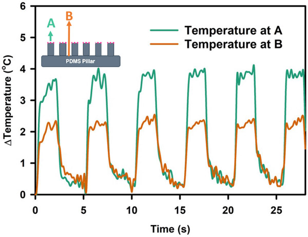
Fig. 9 shows the temperature response of pillar tip (point A) and pillar base (point B) when actuated by a 93 mW/mm2 laser pulse of 2s ON time and 3s OFF time. During the ON cycle, temperature increased up to 4°C ± 0.35°C at the tip of the pillar but around 2°C ± 0.29°C for the base of the pillar. As GNR was embedded mostly at the tip of the PDMS micropillar, heat was generated at point A and then traversed to point B. This caused the temperature difference between the two points. The temperature rise and fall time, which are defined between 10% and 90% of the temperature value change, were measured to 0.54 s ± 0.33 s and 1.10 s ± 0.167 s, respectively. The first pulse took a slightly longer time to build up temperature. The demonstrated range of temperature has also been proven to be adequate for neuromodulation applications as demonstrated by previous studies [15], [16], [29].
Fig. 9.
Temperature response of the tip region and base region of the GNR-embedded PDMS micropillar sample when actuated with (93 mW/mm2). laser pulse.
D. Temperature Response With Varying Laser Parameter
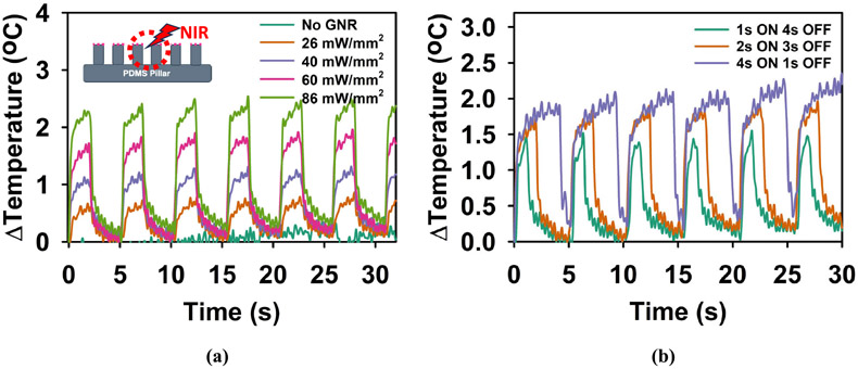
Fig. 10 (a) shows the temperature response of the sample with varying laser power. To see the average temperature change with a laser spot, we measured the emission intensity variation in the tip and base area of the actuated region together. When there is no GNR embedded in the sample, with 26 mW/mm2 laser pulse of 2s ON time and 3s OFF time. Due to this reason, the temperature variation did not follow the laser pulse. The slight fluctuation of temperature with time for no presence of GNR was observed due to noise from the rhodamine B dye signal. Supplementary video 1 shows the rhodamine B emission intensity response of the PDMS micropillar array with no GNR embedded on the tip when actuated with a laser pulse of 2s ON time and 3s OFF time (26 mW/mm2). On the other hand, the sample with GNR showed an increasing trend with increasing laser power. Supplementary video 2 shows the rhodamine B emission intensity response of the PDMS micropillar array with GNR embedded on the tip when actuated with a laser pulse of 2s ON time and 3s OFF time (26 mW/mm2). The measured rise and fall times for different laser power levels were 0.84 s ± 0.167s and 0.9 s ± 0.167 s (26 mW/mm2), 0.84 s ± 0.167 s and 0.90 s ± 0.167 s (40 mW/mm2), 0.67 s ± 0.33 s and 1.06 s ± 0.33 s (60 mW/mm2), 0.34 s ± 0.33 s and 1.35 s ± 0.33 s (86 mW/mm2) respectively. In all cases, the temperature build-up was much more rapid than the temperature loss. It can also be observed that the slight residue temperature increases after each laser pulse. In the case of a liquid environment, which is typically the case for cell culture, the residue heat is expected to be transferred to the surrounding environment.
Fig. 10.
Temperature response of the GNR-embedded micropillar array sample with (a) varying laser actuation power (b) varying On and Off cycle.
Fig. 10 (b) shows the temperature variation with varying ON and OFF cycles of the laser pulse of 60 mW/mm2. It can be observed that the 1s ON cycle was not long enough to bring the temperature variation to a saturated state. However, for the 4s ON cycle, the temperature almost reached the saturated state in each pulse. It is also observed that when the temperature change was more, it took more time for the background temperature to come back to its original state. As the previously demonstrated studies mostly show modulation of temperature with a pulse of 30s or higher ON cycle, our experimental results show the potential to decrease the modulation time to a few seconds. In future work, the variation of the GNR concentration on the tip of the PDMS micropillar array and their photothermal characterizations will be further studied to build up temperature more rapidly with comparatively smaller laser power. In addition, we plan on using our platform to observe the retina neural activity modulation in multiple sites. The biocompatibility and inertness of the materials presented in this work can be a good option for arrayed neuromodulation platforms. Moreover, wireless control of neuronal activity can accelerate the progress of such platforms toward epiretinal implantation. Nevertheless, the inability of photothermal-based stimulation to target specific cells is one of its current disadvantages. Thus, photothermal-based stimulation raises the same issue of specificity as electrical stimulations face. With the development of recent thermogenetics and its ability to express temperature-sensitive receptors in target cells [30], [31], [32], the proposed platform can be a valuable tool to achieve neural stimulation with higher spatiotemporal resolution compared to conventional electrical stimulations
IV. Conclusion
We have demonstrated rapid photothermal response of GNR embedded micropillar array suitable for two-dimensional optically controlled photothermal stimulations. Based on soft lithography employing micro-structured molds, we have presented fabrication procedures of a PDMS-based micropillar array embedded with silica-coated GNRs. It is confirmed by optical transmission through a fabricated micropillar arrayed structure that the absorption peaks from the plasmonic resonance in the embedded GNRs still remained. Silica-coating of GNRs effectively preserves plasmonic resonance without showing its degradation during the GNR embedding process. The measured photothermal actuations of the fabricated pillar array indicate that highly localized temperature changes adequate for neuromodulation are possible with sub-second of rise time and fall time. Given that the strong optical absorption of GNRs is dependent on their physical dimensions, our device can be designed to generate photothermal responses independently from a wide range of light sources. Furthermore, without the need for any physical connections, the high-spatiotemporal stimulation array that allows single pillar or a group of them to be actuated independently, can be easily implemented by our optical control approach. The presented structure has the potential for novel photothermal interfaces that demand a rapid temperature change to stimulate neuron cells with remote optical control.
Supplementary Material
Acknowledgment
The authors thank Youngsik Song for his help in processing the samples for SEM imaging.
This work was supported by the National Institute of Health under Grant 1R16GM145601. Subject Editor E. Meng.
Biographies
Nafis Mustakim received the B.S. degree in electrical and electronic engineering from the Shahjalal University of Science and Technology, Sylhet, Bangladesh, in 2020. He is currently pursuing the Ph.D. degree in electrical engineering with The City College of New York. From 2020 to 2021, he worked as an Embedded System Engineer with Teton Private Ltd., Dhaka, Bangladesh. His research interests include biomimetic actuators, bioMEMS, microfluidics, micro/nanosystems, and optical micromechanical systems.
Luis F. Rodriguez Vera received the B.S. degree in electrical engineering from The City College of New York, with a minor in mathematics and physics. During the B.S. degree, he was with the Institute for Ultrafast Spectroscopy and Lasers, studying light matter interactions of different systems. He is currently with Cadence Design Systems, supporting digital design tools.
Jose Pacheco Pinto received the B.S. degree in electrical engineering from The City College of New York. As a Research Assistant with the Institute for Ultrafast Spectroscopy and Laser, he conducted research on the interaction of lasers with organic tissue and electromagnetic wave detection. His research interests include nanoelectronics, integrated circuit design, and electromagnetics.
Sang-Woo Seo received the B.S. degree in electrical engineering from Ajou University in 1997, the M.S. degree from Gwangju Institute of Science and Technology, South Korea, in 1999, and the Ph.D. degree in electrical engineering from Georgia Institute of Technology, USA, in 2003. From 2004 to 2007, he was a Research Engineer with the Group at Georgia Tech and Duke University, to develop thin film photonic devices and integration methods. He then joined as a Research Scientist with the University of California, Davis, where he worked on developing InP-based chip-scale optical code-division multiplex access and arbitrary waveform generator systems. In 2007, he joined the Department of Electrical Engineering, The City College of New York, NY, USA, where he is currently a Professor. His research interests include heterogeneous optoelectronic device integration, integrated microfluidic/photonic sensors, integrated THz systems, bioMEMs, and optical micromechanical systems.
Footnotes
This article has supplementary material provided by the authors and color versions of one or more figures available at https://doi.org/10.1109/JMEMS.2024.3418373.
Declarations
The authors declare no competing interests.
Contributor Information
Nafis Mustakim, Department of Electrical Engineering, The City College of New York, New York, NY 10031 USA.
Luis F. Rodriguez Vera, Department of Electrical Engineering, The City College of New York, New York, NY 10031 USA; Cadence Design Systems, San Jose, CA 95134 USA.
Jose Pacheco Pinto, Department of Electrical Engineering, The City College of New York, New York, NY 10031 USA.
Sang-Woo Seo, Department of Electrical Engineering, The City College of New York, New York, NY 10031 USA.
Data Availability Statement
All data that support the findings of this study are included within the article (and any supplementary files).
REFERENCES
- [1].Zheng J et al. , “Gold nanorods: The most versatile plasmonic nanoparticles,” Chem. Rev, vol. 121, no. 21, pp. 13342–13453, Nov. 2021, doi: 10.1021/acs.chemrev.1c00422. [DOI] [PubMed] [Google Scholar]
- [2].Taylor ML, Wilson RE, Amrhein KD, and Huang X, “Gold nanorod-assisted photothermal therapy and improvement strategies,” Bioengineering, vol. 9, no. 5, p. 200, May 2022, doi: 10.3390/bioengi-neering9050200. [DOI] [PMC free article] [PubMed] [Google Scholar]
- [3].Stone J, Jackson S, and Wright D, “Biological applications of gold nanorods,” WIREs Nanomedicine Nanobiotechnol., vol. 3, no. 1, pp. 100–109, Jan. 2011, doi: 10.1002/wnan.120. [DOI] [PubMed] [Google Scholar]
- [4].Chakraborty D, Mukherjee A, and Ethiraj KR, “Gold nanorod-based multiplex bioanalytical assay for the detection of CYFRA 21–1 and CA-125: Towards oral cancer diagnostics,” Anal. Methods, vol. 14, no. 37, pp. 3614–3622, Sep. 2022, doi: 10.1039/d2ay01216b. [DOI] [PubMed] [Google Scholar]
- [5].Khan NU, Lin J, Younas MR, Liu X, and Shen L, “Synthesis of gold nanorods and their performance in the field of cancer cell imaging and photothermal therapy,” Cancer Nanotechnol., vol. 12, no. 1, pp. 1–33, Jul. 2021, doi: 10.1186/s12645-021-00092-w.33456622 [DOI] [Google Scholar]
- [6].Darrigues E et al. , “Tracking gold nanorods’ interaction with large 3D pancreatic-stromal tumor spheroids by multimodal imaging: Fluorescence, photoacoustic, and photothermal microscopies,” Sci. Rep, vol. 10, no. 1, pp. 1–14, Feb. 2020, doi: 10.1038/s41598-020-59226-6. [DOI] [PMC free article] [PubMed] [Google Scholar]
- [7].Huang J et al. , “Metal organic framework-coated gold nanorod as an on-demand drug delivery platform for chemo-photothermal cancer therapy,” J. Nanobiotechnol, vol. 19, no. 1, pp. 1–13, Dec. 2021, doi: 10.1186/s12951-021-00961-x. [DOI] [PMC free article] [PubMed] [Google Scholar]
- [8].Jauffred L, Samadi A, Klingberg H, Bendix PM, and Oddershede LB, “Plasmonic heating of nanostructures,” Chem. Rev, vol. 119, no. 13, pp. 8087–8130, Jul. 2019, doi: 10.1021/acs.chemrev.8b00738. [DOI] [PubMed] [Google Scholar]
- [9].Wang X, Li G, Ding Y, and Sun S, “Understanding the photothermal effect of gold nanostars and nanorods for biomedical applications,” RSC Adv., vol. 4, no. 57, pp. 30375–30383, Jul. 2014, doi: 10.1039/c4ra02978j. [DOI] [Google Scholar]
- [10].Liao S et al. , “Improvement of gold nanorods in photothermal therapy: Recent progress and perspective,” Frontiers Pharmacol., vol. 12, Apr. 2021, Art. no. 664123, doi: 10.3389/fphar.2021.664123. [DOI] [PMC free article] [PubMed] [Google Scholar]
- [11].Wang Y and Guo L, “Nanomaterial-enabled neural stimulation,” Frontiers Neurosci., vol. 10, p. 69, Mar. 2016, doi: 10.3389/fnins.2016.00069. [DOI] [PMC free article] [PubMed] [Google Scholar]
- [12].Zhao D, Huang R, Gan J-M, and Shen Q-D, “Photoactive nanomaterials for wireless neural biomimetics, stimulation, and regeneration,” ACS Nano, vol. 16, no. 12, pp. 19892–19912, Dec. 2022, doi: 10.1021/acsnano.2c08543 [DOI] [PubMed] [Google Scholar]
- [13].Mou Z, You M, and Xue W, “Gold nanorod-assisted near-infrared stimulation of bullfrog sciatic nerve,” Lasers Med. Sci, vol. 33, no. 9, pp. 1907–1912, Dec. 2018, doi: 10.1007/s10103-018-2554-1. [DOI] [PubMed] [Google Scholar]
- [14].Yong J et al. , “Gold-nanorod-assisted near-infrared stimulation of primary auditory neurons,” Adv. Healthcare Mater, vol. 3, no. 11, pp. 1862–1868, Nov. 2014, doi: 10.1002/adhm.201400027. [DOI] [PubMed] [Google Scholar]
- [15].Yoo S, Hong S, Choi Y, Park J-H, and Nam Y, “Photothermal inhibition of neural activity with near-infrared-sensitive nanotransducers,” ACS Nano, vol. 8, no. 8, pp. 8040–8049, Aug. 2014, doi: 10.1021/nn5020775. [DOI] [PubMed] [Google Scholar]
- [16].Kang H, Hong W, An Y, Yoo S, Kwon H-J, and Nam Y, “Thermoplasmonic optical fiber for localized neural stimulation,” ACS Nano, vol. 14, no. 9, pp. 11406–11419, Sep. 2020, doi: 10.1021/acsnano.0c03703. [DOI] [PubMed] [Google Scholar]
- [17].Richardson RT, Ibbotson MR, Thompson AC, Wise AK, and Fallon JB, “Optical stimulation of neural tissue,” Healthcare Technol. Lett, vol. 7, no. 3, pp. 58–65, Jun. 2020, doi: 10.1049/htl.2019.0114. [DOI] [PMC free article] [PubMed] [Google Scholar]
- [18].Eom K et al. , “Enhanced infrared neural stimulation using localized surface plasmon resonance of gold nanorods,” Small, vol. 10, no. 19, pp. 3853–3857, Oct. 2014, doi: 10.1002/smll.201400599. [DOI] [PubMed] [Google Scholar]
- [19].Mahadevan G, Sheardown H, and Selvaganapathy P, “PDMS embedded microneedles as a controlled release system for the eye,” J. Biomaterials Appl, vol. 28, no. 1, pp. 20–27, Jul. 2013, doi: 10.1177/0885328211433778. [DOI] [PubMed] [Google Scholar]
- [20].Nikoobakht B and El-Sayed MA, “Preparation and growth mechanism of gold nanorods (NRs) using seed-mediated growth method,” Chem. Mater, vol. 15, no. 10, pp. 1957–1962, May 2003, doi: 10.1021/cm020732l. [DOI] [Google Scholar]
- [21].Song Y, Azmand HR, and Seo S-W, “Rapid photothermal actuation of light-addressable, arrayed hydrogel columns in a macroporous silicon membrane,” Sens. Actuators A, Phys, vol. 301, Jan. 2020, Art. no. 111729, doi: 10.1016/j.sna.2019.111729. [DOI] [PMC free article] [PubMed] [Google Scholar]
- [22].Wu W-C and Tracy JB, “Large-scale silica overcoating of gold nanorods with tunable shell thicknesses,” Chem. Mater, vol. 27, no. 8, pp. 2888–2894, Apr. 2015, doi: 10.1021/cm504764v. [DOI] [PMC free article] [PubMed] [Google Scholar]
- [23].Pellas V et al. , “Gold nanorod coating with silica shells having controlled thickness and oriented porosity: Tailoring the shells for biosensing,” ACS Appl. Nano Mater, vol. 4, no. 9, pp. 9842–9854, Sep. 2021, doi: 10.1021/acsanm.1c02297. [DOI] [Google Scholar]
- [24].Liu J et al. , “Antibody-conjugated gold nanoparticles as nanotransducers for second near-infrared photo-stimulation of neurons in rats,” Nano Converg., vol. 9, no. 1, pp. 1–13, Mar. 2022, doi: 10.1186/s40580-022-00304-y. [DOI] [PMC free article] [PubMed] [Google Scholar]
- [25].Wu X et al. , “Tether-free photothermal deep-brain stimulation in freely behaving mice via wide-field illumination in the near-infrared-II window,” Nature Biomed. Eng, vol. 6, no. 6, pp. 754–770, Mar. 2022, doi: 10.1038/s41551-022-00862-w. [DOI] [PMC free article] [PubMed] [Google Scholar]
- [26].Yang F, Wu X, Cai S, and Hong G, “Bioinspired nanotransducers for neuromodulation,” Nano Res., vol. 17, no. 2, pp. 618–632, Feb. 2024, doi: 10.1007/s12274-023-6136-6. [DOI] [Google Scholar]
- [27].Zhu Q et al. , “Recent advances in nanotechnology-based functional coatings for the built environment,” Mater. Today Adv, vol. 15, Aug. 2022, Art. no. 100270, doi: 10.1016/j.mtadv.2022.100270. [DOI] [Google Scholar]
- [28].Ko F-H, Weng L-Y, Ko C-J, and Chu T-C, “Characterization of imprinting polymeric temperature variation with fluorescent rhodamine B molecule,” Microelectronic Eng., vol. 83, nos. 4–9, pp. 864–868, Apr. 2006, doi: 10.1016/j.mee.2006.01.009. [DOI] [Google Scholar]
- [29].Farah N et al. , “Holographically patterned activation using photoabsorber induced neural–thermal stimulation,” J. Neural Eng, vol. 10, no. 5, Oct. 2013, Art. no. 056004, doi: 10.1088/1741-2560/10/5/056004. [DOI] [PubMed] [Google Scholar]
- [30].Ermakova YG et al. , “Thermogenetics as a new direction in controlling the activity of neural networks,” Neurosci. Behav. Physiol, vol. 50, no. 8, pp. 1018–1023, Oct. 2020, doi: 10.1007/s11055-020-01001-1. [DOI] [Google Scholar]
- [31].Manger PR et al. , “Amplification of potential thermogenetic mechanisms in cetacean brains compared to artiodactyl brains,” Sci. Rep, vol. 11, no. 1, pp. 1–15, Mar. 2021, doi: 10.1038/s41598-021-84762-0. [DOI] [PMC free article] [PubMed] [Google Scholar]
- [32].Braun A, Borst A, and Meier M, “Disynaptic inhibition shapes tuning of OFF-motion detectors in drosophila,” Current Biol., vol. 33, no. 11, pp. 2260–2269, Jun. 2023, doi: 10.1016/j.cub.2023.05.007. [DOI] [PubMed] [Google Scholar]
Associated Data
This section collects any data citations, data availability statements, or supplementary materials included in this article.
Supplementary Materials
Data Availability Statement
All data that support the findings of this study are included within the article (and any supplementary files).


