

Abstract
The Hewlett Packard Enterprise–Cray EX Frontier is the world’s first and fastest exascale supercomputer, hosted at the Oak Ridge Leadership Computing Facility in Tennessee, United States. Frontier is a significant electricity consumer, drawing 8–30 MW; this massive energy demand produces significant waste heat, requiring extensive cooling measures. Although harnessing this waste heat for campus heating is a sustainability goal at Oak Ridge National Laboratory (ORNL), the 30 °C–38 °C waste heat temperature poses compatibility issues with standard HVAC systems. Heat pump systems, prevalent in residential settings and some industries, can efficiently upgrade low-quality heat to usable energy for buildings. Thus, heat pump technology powered by renewable electricity offers an efficient, cost-effective solution for substantial waste heat recovery. However, a major challenge is the absence of benchmark data on high-performance computing (HPC) heat generation and waste heat profiles. This paper reports power demand and waste heat measurements from an ORNL HPC data centre, aiming to guide future research on optimizing waste heat recovery in large-scale data centres, especially those of HPC calibre.
Subject terms: Energy management, Energy conservation
Background & Summary
Big data applications have become popular with the wide implementation of cloud computing in data-driven businesses. Data centres worldwide are estimated to consume over 300 TWh of energy1; data centres in the United States account for nearly 2% of the country’s total electricity consumption2. Depending on the location and power density of these data centres, cooling can comprise 33%–40% of their energy consumption, leading to the use of hundreds of billions of gallons of water annually3 as common methods to cool data center computers feature the use of cooling towers. Additionally, the data centre sector is anticipated to expand at a compound annual growth rate of 20% through 20304, which will lead to even more energy and water usage.
The Oak Ridge Leadership Computing Facility (OLCF)—home to a high-performance computing (HPC) data centre and, notably, the top-ranked Frontier Hewlett Packard Enterprise Cray EX exascale supercomputer (see Fig. 1)—stands as one of the most significant electricity consumers on the campus of the US Department of Energy’s Oak Ridge National Laboratory (ORNL). Frontier, despite its efficient design, consumes between 8 and 30 MW of electricity5—equivalent to the energy consumption of several thousand homes. Concurrently, the heat generated by the supercomputer’s processors is dispersed through a cooling system that further expends substantial energy and water usage6 (i.e., substantial waste heat is released into the atmosphere by four evaporative cooling towers). This process demands a staggering 9,000–22,700 L of water to be pumped through the supercomputer’s cooling loop every minute to ensure efficient heat dissipation. To fulfil the laboratory’s commitment to efficient, sustainable operations and to decrease greenhouse gas (GHG), harnessing a portion of the 8–28 MW of waste heat for heating needs (e.g., hot water, space heating) in ORNL campus buildings is imperative. However, a key challenge is that the water temperature derived from the waste heat ranges from 30 °C to 38 °C. This low-grade energy is not directly compatible with building HVAC distribution systems for hot water and space heating, which typically require fluid temperatures of 85 °C.
Fig. 1.

Frontier—the world’s fastest supercomputer—ushered in the exascale computing era. Frontier is located at Oak Ridge National Laboratory’s Oak Ridge Leadership Computing Facility.
Heat pump technology is a clean, efficient method of transferring heat, capable of being powered by renewable electricity7,8. Using a refrigerant to transfer heat between different sources enables leaner, more ecofriendly building operations. A high-temperature heat pump is a promising solution to harvest the 30 °C–38 °C low-grade heat energy emanating from the HPC data centre. This technology uses an evaporator to draw energy from the 30 °C–38 °C water heat source of the HPC data centre, transferring it to a refrigerant gas. As the compressor intensifies the gas’s pressure, the gas’s temperature also rises. The condenser then facilitates the transfer of heat from the refrigerant to an 85 °C heat sink, which is used for water and space heating applications in the facilities near the data centre. Concurrently, the refrigerant reverts to its liquid form. The cycle is then reset by the expansion valve, which reduces the refrigerant’s pressure, prompting evaporation. By leveraging this method, waste heat from the HPC data centre is efficiently repurposed for district heating. This process replaces the need for hot steam traditionally produced by natural gas boilers. The result not only conserves energy but also significantly reduces GHG emissions, furthering the ORNL’s sustainability and decarbonization goals for campus structures. Recovering and updating this waste heat is a promising method to reduce the GHG emission inventories for the ORNL campus, which were quantified to be 236,456 MtCO2e9 by considering factors such as consumed electricity, natural gas, fugitive gases and refrigerants, fuel for vehicles and equipment, employee commuting, and transmission and distribution losses.
One of the key challenges for designing and developing an efficient, cost-effective, high-temperature heat pump system to recover low-grade waste heat is the lack of available datasets to benchmark HPC heat generation and to record waste heat profiles. This paper identifies waste heat generated from HPC and collects field operational datasets for an ORNL HPC data centre. This information will provide a guide for research on development of a highly efficient, cost-effective waste heat recovery system for a data centre—specifically an HPC data centre.
Methods
Frontier, the world’s first and fastest exascale supercomputer, is located at the OLCF in Oak Ridge, Tennessee, United States. The Frontier computing system was designed to integrate cutting-edge hardware and software technologies with a complex variety of interconnecting technologies that enable high-speed data transfer among the system’s 9,402 nodes9. Figure 2a shows the entire Frontier computing system, which comprises 74 computing rack cabinets as well as many supporting and management rack cabinets. Each computing rack cabinet hosts 64 blades, as shown in Fig. 2b,c. The blades are a type of compact server architecture commonly used in supercomputers and data centres; they are designed to be densely packed within a chassis to help optimize space utilization. In Frontier, each blade server consists of two nodes, which are the individual computing units, as shown in Fig. 2d. Each node contains four GPUs and one CPU along with 4 TB of flash memory and storage, as shown in Fig. 2e.
Fig. 2.

Real computer components and their cooling hardware for the Frontier high-performance computing system at Oak Ridge National Laboratory: (a) 74 compute rack cabinets; (b) 64 blades in each rack cabinet; (c) coolant inlet and outlet in each blade; (d) two nodes in an open blade; (e) four GPUs, one CPU, 4 TB of flash memory, and their cooling loops in each node; (f) coolant distribution unit; and (g) high-temperature water return and supply. (CPU = central processing unit, GPU = graphics processing unit, TCS = tertiary cooling system).
To prevent the data centre or supercomputer from overheating, effective cooling systems are essential to remove heat generated by the nodes within densely packed blade servers and to ensure that the heat is efficiently transferred from the facility and released into the environment. Figures 2e–g, 3 show the details of the primary, secondary, and tertiary cooling loops for removing heat from the 9,402 nodes and transferring the heat to node cooling circuits, coolant distribution units, large-scale heat exchangers, cooling towers, and other large facilities. Briefly, the heat moves from the tertiary cooling loop to the secondary cooling loop and then to the primary cooling loop. The tertiary cooling loop is the direct computing hardware cooling loop. The secondary cooling loop is part of the facility cooling system and is responsible for dissipating heat collected by the tertiary cooling loop. The secondary cooling loop also includes a waste heat recovery subloop, enabling waste heat recovery to heat water for other applications, such as building space and water heating. The primary cooling loop is the cooling tower loop, which primarily helps dissipate heat generated by the Frontier computing system to the atmosphere.
Fig. 3.

Cooling architecture of the Frontier high-performance computing system at the Oak Ridge Leadership Computing Facility at Oak Ridge National Laboratory. (HWR = heating water return; HWS = heating water supply; WHRD = waste heat recovery device; CTS = cooling tower system; CTWP = cooling tower water pump; HX = heat exchanger; HTWP = high-temperature water pump). Nos. 1–4 cooling subloops consisting of 4 CTWPs, 4 HXs and 4 HTWPs.
The cooling of blades and nodes in the tertiary cooling loop is shown in Fig. 2b–e. Figure 2e shows the complex cooling circuits in each node, in which a liquid coolant absorbs and carries away heat generated by the CPU, GPUs, memory modules, and other critical hardware components within the computing nodes. In Fig. 2b, the blue port is the chilled coolant entry to the blade and nodes, and the red port is the heated coolant outlet flowing to a coolant distribution unit (CDU). Figure 2f displays a CDU, a component of the cooling system responsible for distributing chilled coolant to the computing rack cabinets, storage rack cabinets, and other hardware devices. The Frontier supercomputing cabinet cooling group comprises 25 CDUs, and each CDU provides cooling for three rack cabinets. CDUs are intended to maintain the allowable temperature of the IT equipment within specified limits (i.e., the allowable temperature of 15 °C–32 °C, based on ASHRAE guidance10).
The secondary cooling loop is shown in central energy plant (CEP) B (Fig. 3). The secondary cooling loop includes four cooling subloops (i.e., Nos. 1–4 cooling subloops); Nos. 1–3 cooling subloops are currently used to transfer waste heat from the tertiary cooling loop to the primary, whereas No. 4 cooling loop is a backup. Every minute, 9,000–22,700 L of water is pumped through the supercomputer’s cooling loop to carry away 97%–99% of the waste heat. Figure 2g displays the coolant return and supply of the secondary cooling loop to the CDUs. Also, the secondary cooling loop can be connected to a chiller in the primary cooling loop, enabling waste heat recovery to heat water for building space and water heating. The primary cooling loop, shown in CEP A (Fig. 3), can handle up to a 40 MW heating load using large pumps, heat exchangers, and four 36,000 kg cooling towers. The system processes and eventually dissipates waste heat into the external atmosphere.
Data Records
Real-time measurements of Frontier’s power and energy characteristics were recorded every 10 min from January 1st to December 31th, 2023. The data are stored on Figshare11, a shared platform that can be accessed publicly and used to support energy analysis and waste heat recovery development of the Frontier supercomputer system facility. The data file covers the measurements of the supply and return coolant temperature and coolant flow of three cooling subloops in the secondary cooling loop; the subloops are currently used to transfer waste heat from the tertiary cooling loop to the primary. Moreover, the data file lists the calculation results of waste heat available from the three cooling subloops and their total waste heat available. Waste heat stream from each of the three cooling subloops is calculated based on the difference between return and supply coolant temperature, as well as coolant flow, in each cooling subloop. Total waste heat is the summation of the waste heat from the three cooling subloops. The coolant is a 50%/50% solution of water and ethylene glycol with a density of 1,060 kg/m3 and a specific heat of 3.5 kJ/kg-K. The data file also records the power demand measurements of the Frontier supercomputer and accessory systems. In addition, the data file lists the calculation parameter of power usage effectiveness, a ratio that measures how efficiently a computer data centre uses energy. PUE is calculated by dividing the total amount of energy used by the data centre by the amount of energy used by the HPC equipment. All the data are saved in an Excel XLSX format.
Although data measurements were taken from January 1st to December 31st, 2023, at 10-minute intervals, approximately 440 hours of data over the entire year were lost due to planned maintenance and unplanned downtime of Frontier HPC and data acquisition systems. These intervals account for less than 5% of Frontier’s operating time. Therefore, the recorded data is still sufficient to summarize useful power demand and waste heat information for the Frontier supercomputer system facility.
Technical Validation
Data measurement and instrumentation uncertainty
The Frontier system was fully instrumented to measure its performance in terms of volumetric flow rates, temperatures, and power. Data were collected from the facility’s building automation system, a Johnson Controls Metasys system. Its Extended Application and Data Server historian stored data at 15 min intervals. Through the Metasys user interface, trend queries were retrieved with a custom time frame of 1 year, and data were exported to CSV files, which were then imported and compiled in a Microsoft Excel spreadsheet. Charts were generated, and minimum, maximum, and average values were calculated for each parameter. Given the demand for heating water, a reasonable base load was determined by formulating the minimum load during the summer when demand for heating water was at a minimum. The building automation system is a distributed control system with direct digital controllers in a system architecture that includes network automation engines (NAEs). The direct digital controllers’ advanced field equipment controllers also have expansion modules for additional inputs and outputs. The field equipment controllers receive sensor/transducer output signals and communicate readings to NAEs with Building Automation and Control Networks over Internet Protocol (i.e., BACnet/IP). Then, the Extended Application and Data Server retrieves the trend data from the NAEs to store in its historical database (i.e., Microsoft Structured Query Language [(SQL) server), which can then be retrieved with the Metasys user interface.
A detailed list of the measurement points and specifications of the instrumentations is given in Table 1; the technical quality of the dataset can be understood through the accuracy of the measurements.
Table 1.
Measurement variables and instrumentation.
| Measured variable | Instruments | Range | Accuracy |
|---|---|---|---|
| Supply water temperature and cooling loop temperatures | TE-635AM-2, 1 K ohm platinum RTD; TE-6300W-102, 1 K ohm platinum RTD | −45.6 °C–104.4 °C | ±[0.15 °C + 0.002*T (°C)] |
| Total cooling water mass flow rate | FT-3200 transmitter, electromagnetic flow meter (meter size = 12 in.) | 128–43,200 L/min | ±0.2% at 0.49 m/s~10.0 m/s; ±0.001 m/s at <0.49 m/s |
| Frontier and accessory power demand | PowerLogic™ PM89M2600 and PM89M0024 | Max voltage: 250 V AC; max current: 8 A at 250 V AC | 0.3% full scale |
RTD = resistance temperature detector.
Assessing supercomputer data
Several sets of monitored or calculated variables were selected to demonstrate the characteristics of the supercomputer system power demand, power usage effectiveness (PUE), and waste heat generation. Figure 4 shows the Frontier system power demand and PUE measured for 1 year from January 1st to December 31st, 2023. Figure 4a plots the Frontier system’s 1-year transient power demand, which was averaged at 12.2 MW with an 8.5 MW idle power usage and 28.5 MW peak power usage. In Fig. 4b, the average power usage of the accessory cooling system is 0.6, with an idle power usage of 0.5 MW and peak usage of 1.1 MW. However, as shown in Fig. 4a,b, the transient power demands of the Frontier system and accessory occasionally drop below their idling power level, possibly because of the planned and unplanned shutdown of the computer and accessories. The average PUE is 1.05, with the lower end of this spectrum achieved primarily through the use of evaporative cooling (i.e., using cooling towers) instead of mechanical cooling (i.e., using chilled water). The energy consumption in the former approach is significantly lower compared with the latter. Consequently, the mechanical (chilled water) cooling approach results in a higher monthly average PUE. The results are shown in Fig. 4c.
Fig. 4.

Transient power demand characteristics of the Frontier supercomputer: (a) supercomputer power usage, (b) accessory cooling system power demand, and (c) power usage effectiveness.
Figure 5 shows the operation time statistics of the supercomputer’s total power demand, cooling system power usage, and power usage effectiveness. This clearly demonstrates that more than 95% of Frontier power demand is between 8.0 and 20.0 MW, and more than 99% of Frontier accessory cooling operation time causes power usage between 0.5 and 0.9 MW. Thus, more than 99% of PUE is distributed between 1.03 and 1.08. This indicates that Frontier is operating under an efficient mode. Studies in the public domain show a wide range of PUE values for data centres, but the overall average tends to be around 1.812, significantly more than Frontier.
Fig. 5.

Power demand statistics of the Frontier supercomputer: (a) supercomputer total power demand, (b) accessory (i.e., cooling) system power usage, and (c) power usage effectiveness.
Figure 6 shows waste heating generation from the Frontier supercomputer facility, including the total and individual waste heat from the three cooling subloops (see Fig. 6a). The results shown in Fig. 6b indicate that most of the waste heat is around 5–15 MW, which is a substantial amount of energy.
Fig. 6.

Waste heat generation characteristics of Frontier supercomputer: (a) overall waste heat and individual waste heat from the three cooling subloops, and (b) operation statistics of overall transient waste heat.
In addition, Fig. 7 shows the detailed single-day profiles of the power demand, PUE, waste heat, and coolant flow and temperature. The single-day data indicate that, although substantial waste energy is available, the waste heat temperature is less than 45 °C. Thus, significant opportunities exist for using heat pump technologies to recycle waste heat and achieve 50 °C space heating and 85 °C water heating9,13, for ORNL campus buildings.
Fig. 7.
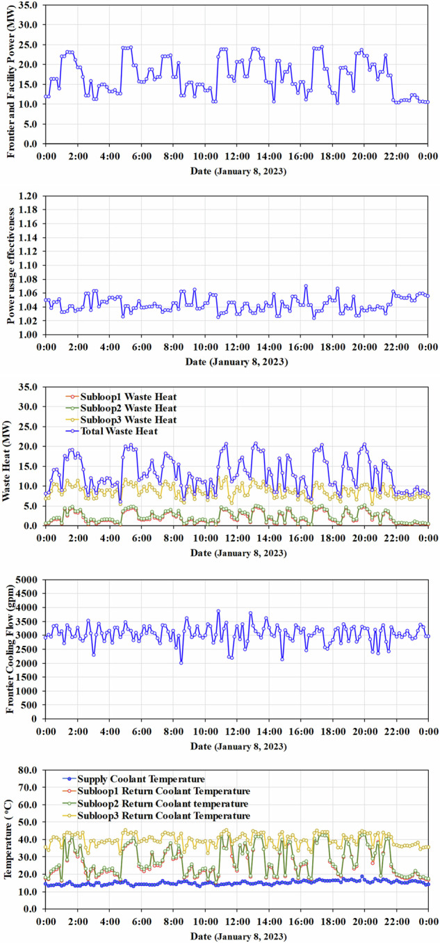
Single-day profiles of the power demand, PUE, waste heat, and coolant flow and temperature on January 8th, 2023.
Usage Notes
The paper presents a 1-year dataset of Frontier, the world’s fastest supercomputer that ushered in the exascale computing era. This dataset includes power demand, waste heat, coolant flow rates, and temperatures. The dataset is available in the data repository Figshare11, and the data file is in an Excel XLSX format. The Excel data file lists two worksheets (i.e., Readme and Frontier2023), and has 12 plots showing the 1-year and 1-day profiles for Frontier total power demand, accessory power usage, coolant temperature, coolant flow, waste heat, and PUE. The worksheet titled Frontier2023 shows 1-year real-time measurements, and the worksheet of Readme provides a useful description of the title of each column shown in the datasheet of Frontier2023 to assist users of the data.
Acknowledgements
This work was sponsored by the Sustainable ORNL Potential Showcase Project program. The authors thank ORNL colleagues for their help and support. The Oak Ridge Leadership Computing Facility is a US Department of Energy Office of Science User Facility. The authors also thank Jessica Hingtgen and Wendy Hames for technical editing. Note: This manuscript has been authored by UT-Battelle, LLC, under contract DE-AC05-00OR22725 with the US Department of Energy (DOE). The US government retains and the publisher, by accepting the article for publication, acknowledges that the US government retains a nonexclusive, paid-up, irrevocable, worldwide license to publish or reproduce the published form of this manuscript, or allow others to do so, for US government purposes. DOE will provide public access to these results of federally sponsored research in accordance with the DOE Public Access Plan (http://energy.gov/downloads/doe-public-access-plan).
Author contributions
J. Sun: investigation and writing (original draft); Z. Gao: funding acquisition, supervision, investigation, resources, and writing (original draft and revision); D. Grant: data collection, resources and writing; P. Wang: investigation discussion and writing (original draft and revision); C.M. Yang: investigation discussion and writing; P. Boudreaux: investigation discussion and writing; S. Kowalski: investigation discussion and writing (original draft and revision); S. Huff: investigation discussion; K. Nawaz: investigation discussion and writing.
Code availability
N/A
Competing interests
The authors declare no competing interests.
Footnotes
Publisher’s note Springer Nature remains neutral with regard to jurisdictional claims in published maps and institutional affiliations.
References
- 1.Bashrousch, R. & Lawrence, A. Beyond PUE: Tackling IT’s Wasted Terawatts. UII-34, v1.0, https://uptimeinstitute.com/uptime_assets/80ae92ca9b8dfa363a077cb537f51870777499a39218906efc6d4e37e28ac3a0-beyond-pue-tackling-its-wasted-terawatts.pdf (Uptime Institute Intelligence, 2020).
- 2.Masanet, E., Shehabi, A., Lei, N., Smith, S. & Koomey, J. Recalibrating global data center energy-use estimates. Science367(6481), 984–986 (2020). [DOI] [PubMed] [Google Scholar]
- 3.Shehabi, A. et al. United States Data Center Energy Usage Report. https://eta.lbl.gov/publications/united-states-data-center-energy (Lawrence Berkeley National Laboratory, 2016).
- 4.Siddik, M., Shehabi, A. & Marston, L. The environmental footprint of data centers in the United States. Environ. Res. Lett. 16 (2021).
- 5.Oak Ridge National Laboratory. High-Performance Computing at ORNLhttps://my.matterport.com/show/?m=iBfbj7ET4LT (n.d.), (Accessed: 9 July 2024).
- 6.Turczyn, C. Pioneering Frontier: Planning Aheadhttps://www.olcf.ornl.gov/2021/02/18/pioneering-frontier-planning-ahead/ (2021).
- 7.Baxter, V. D. & Munk, J. D. Field testing of two prototype air-source integrated heat pumps for net zero energy home (nZEH) application. IEA Heat Pump Centre Newsletter35(3), 38–43 (2017).
- 8.Tomlinson, J. J., Rice, C. K., Murphy, R. W. & Gao, Z. Assessment and Initial Development of a Small, High-Efficiency Heat Pump System for NZEH (Oak Ridge National Laboratory, 2005).
- 9.Gao, Z. et al. ORNL Campus Sustainability and Decarbonization Using Waste Heat Recovery from the Oak Ridge Leadership Computing Facility’s High-Performance Computing Data Center No. ORNL/TM-2023/3218. (Oak Ridge National Laboratory, 2024).
- 10.ASHRAE. 2021 Equipment Thermal Guidelines for Data Processing Environments (2021).
- 11.Grant, D. et al. Frontier HPC & Facility Data. figshare. Dataset.10.6084/m9.figshare.24391240.v4 (2024).
- 12.National Renewable Energy Laboratory. High-Performance Computing Data Center Power Usage Effectivenesshttps://www.nrel.gov/computational-science/measuring-efficiency-pue.html#:~:text=Studies%20show%20a%20wide%20range,power%20delivered%20to%20computing%20equipment (n.d.) (Accessed: 9 July 2024)
- 13.Wang, P. et al. District heating utilizing waste heat of a data center: High-temperature heat pumps. Energy and Buildings315, 114327 (2024). [Google Scholar]
Associated Data
This section collects any data citations, data availability statements, or supplementary materials included in this article.
Data Citations
- Grant, D. et al. Frontier HPC & Facility Data. figshare. Dataset.10.6084/m9.figshare.24391240.v4 (2024).
Data Availability Statement
N/A