

Abstract
The orbital Hall effect in light materials has attracted considerable attention for developing orbitronic devices. Here we investigate the orbital torque efficiency and demonstrate the switching of the perpendicularly magnetized materials through the orbital Hall material, i.e., Zr. The orbital torque efficiency of approximately 0.78 is achieved in the Zr orbital Hall material with the perpendicularly magnetized [Co/Pt]3 sample, which significantly surpasses that of the perpendicularly magnetized CoFeB/Gd/CoFeB sample (approximately 0.04). Such a notable difference is attributed to the different spin-orbit correlation strength between the [Co/Pt]3 sample and the CoFeB/Gd/CoFeB sample, confirmed through theoretical calculations. Furthermore, the full magnetization switching of the [Co/Pt]3 samples with a switching current density of approximately 2.6×10⁶ A/cm2 has been realized through Zr, which even outperforms that of the W spin Hall material. Our finding provides a guideline to understand orbital torque efficiency and paves the way for developing energy-efficient orbitronic devices.
Subject terms: Spintronics, Spintronics
Orbitronics opens an avenue for developing energy-efficient memory and logic devices through orbital Hall effect. Here, the authors realize the magnetization switching of perpendicularly magnetized materials through the orbital torque.
Introduction
The demand for energy-efficient electronic devices has accelerated the efforts to carry and store information by utilizing the spin angular momentum (S) of electrons over the past decade. Spin Hall effect (SHE) is a physical phenomenon in which the transverse spin currents (JS) can be generated under an external electric field (E) in materials with strong spin-orbit coupling (SOC)1–12, analog to the Hall effect with transverse charge current under perpendicular magnetic field13. By constructing ferromagnetic/nonmagnetic (FM/NM) heterostructure where the NM layer with strong SOC serves as a spin Hall material, the charge current (JC) is converted into JS in the NM layer through SHE, and the JS is injected into the adjacent FM layer, to induce spin-orbit torque (SOT)9–12, and switch the magnetization of the FM layer for designing energy-efficient spintronic memory and logic devices3–5,14–19. Most recent efforts have shifted towards exploring the orbital angular momentum (L) in materials without depending on SOC for developing orbitronic memory and logic devices20–32. Generally, orbital quenching caused by crystal fields prevents significant dynamical behaviors of orbital degrees. However, recent studies have shown that the orbital texture caused by orbital hybridization can generate finite orbital angular momentum along the direction of E×k when the E is applied22,23. That leads to another physical phenomenon of the orbital Hall effect (OHE), where the orbital current can be generated in a transverse direction under the E. The large orbital Hall conductivity (σOHE) of the light materials (LMs), which are defined as materials with weak SOC, mainly including the 3d (e.g. Ti, Mn, Cr, V, Ni, Cu) and 4d (e.g., Zr, Nb, Mo, Tc, Ru, Rh, Pd, Ag) metals, can efficiently convert charge current to orbital current21,23,26,33. Furthermore, in the FM/NM heterostructure where the NM layer with weak SOC serves as an orbital Hall material (OHM), the orbital current (JL) originated from OHE in the NM layer can also exert orbital torque (OT) for the magnetization switching24–27, which enters the adjacent FM layer and converting it into spin current via the SOC of the FM layer, switching the magnetization of the FM layer26,27,34–36. The orbital-torque efficiency (ξOT) depends on not only the orbital Hall angle (θOHE) of the LMs but also the orbital-to-spin conversion coefficient (ηL-S) of the adjacent FM layers26,27.
Recently, the ξOT and θOHE have been experimentally investigated in the LMs through methods like the magneto-optical Kerr effect, spin-torque ferromagnetic resonance, harmonic Hall effect, anomalous Hall effect (AHE), and Hanle magnetoresistance26,27,33–46. The ξOT and θOHE of Ti26,34, Cr35–37,39, and Mn40,41 systems have been evaluated. The θOHE of the single Cr39 and Mn40 layers have been estimated to be ~0.28 and 0.016, respectively. The ξOT of Ti/Ni34, Cr/CoTb36, and Mn/Gd/Co41 systems are about 0.13, −0.57, and −0.15, respectively. Most recently, the experiment has confirmed that the contribution originated from OHE dominates the torque compared to the SHE in the light metal Zr systems, which has the large orbital Hall conductivity (σOHE) of 5300 (ћ/e) Ω−1 cm−1 and small spin Hall conductivity (σSHE) of −170 (ћ/e) Ω−1 cm−1 33,38. To date, however, there has been limited exploration of the experimental magnetization switching of the FM layer with perpendicular magnetic anisotropy (PMA) through the OT. This is primarily due to the demanding requirements of both PMA and large ηL-S for the adjacent FM layer, let alone the industrial-compatible PMA samples for designing the energy-efficient orbitronic memory and logic devices.
In this work, we first provided the difference between the SOT and OT, then fabricated the samples and conducted experimental investigations into the ξOT of the OHM, Zr, with different adjacent PMA FM materials, (i.e., [Co (0.3 nm)/Pt (0.7 nm)]3 and Co20Fe60B20 (0.8 nm)/Gd (1.2 nm)/Co20Fe60B20 (1.1 nm) samples, hereafter termed as [Co/Pt]3 and CFB/Gd/CFB, respectively) through the second harmonic measurement. It is found that the Zr/[Co/Pt]3 sample has larger ξOT (~0.78) compared to the Zr/CFB/Gd/CFB sample (~0.04), indicating that the ξOT is determined by both θOHE of OHMs and the ƞL-S of the FM layer. Subsequently, we performed the magnetization switching of these samples via the OT and found that the Zr OHM can easily switch the [Co/Pt]3 samples with a lower switching current density (Js) than the CFB/Gd/CFB sample. The observed distinction is also manifested by their different ξOT. Meanwhile, first-principles calculations have been employed to calculate the spin-orbit correlation to obtain the ηL-S of the [Co/Pt]3 and CFB/Gd/CFB samples, which indicates a larger ηL-S of the [Co/Pt]3 than that of the CFB/Gd/CFB samples, providing insight into the underlying physical mechanism for experimental results. These results highlight the significance of the spin-orbit correlation of the PMA FM layer, offering valuable insights for developing orbitronic electronics.
Results
Spin-orbit torque (SOT) and orbital torque (OT)
In the SOT system, the pivotal factor lies in the properties of the spin Hall Materials (SHMs). In the SHM/FM heterostructures, the conversion of charge current into spin current occurs through the SHMs due to their SOC. The spin-torque efficiency (ξSOT) is determined by θSHE, as described by , where the e, ћ, and σxx are the charge of an electron, reduced Planck constant, and electrical conductivity of SHM, respectively, depends critically on the σSHE and thus the SOC of SHMs, which barely relies on the properties of the adjacent FM layers3–5,17–19, as shown in Fig. 1a. Common SHMs encompass heavy metals (HMs, e.g. Ta, W, Pt), topological materials (TMs, e.g. Bi0.9Sb0.1, Bi2Se3, WTe2)3–5,17–19, etc. Generally, the HMs have the σSHE around 102 ~ 103 (ћ/e) Ω−1 cm−1 and the θSHE around 0.1-0.42. The TMs with the strong SOC could have even larger σSHE ~ 104 ћ/e Ω−1 cm−1, thus the θSHE can reach 2-753–5,17–19. For the OT system, as depicted in Fig. 1b, the properties of both the OHM and the adjacent FM layers play an important role. In the OHM/FM heterostructures, the charge current can be converted to orbital current in the LMs, then transmitted into the FM layers and converted to spin current through the orbital-to-spin conversion of the FM layers26,27. The ξOT depends on the , as , where σxx is the electrical conductivity of OHM26,27,34,35. The LMs, such as Ti, Zr, Cr, Mn, Nb, Ru, and Cu, exhibit the σOHE of about 103 (ћ/e) Ω−1 cm−1, even surpassing the σSHE of the HMs21,22,26,38. Therefore, the ξSOT depends solely on the strong SOC of SHMs to obtain a large θSHE to convert charge current to spin current. However, the ξOT is determined by both the large θOHE of OHMs for charge-to-orbital current conversion and the SOC of the FM layer to achieve large ƞL-S for orbital-to-spin current conversion. On the other hand, by far, the FM materials employed to investigate the ξOT of the OHM/FM systems only focus on the in-plane ferromagnets with the relatively larger ηL-S (~0.0192-0.0455), e.g., CoFe, Co, Ni, however, there are very few materials exhabiting the PMA27. To realize the efficient magnetization switching for realistic industrial applications through the OHE, exploring the OHM/FM systems with the larger σOHE of the OHMs and the larger ηL-S of the PMA FM layers will be very crucial.
Fig. 1. Spin-orbit torque (SOT) and orbital torque (OT).
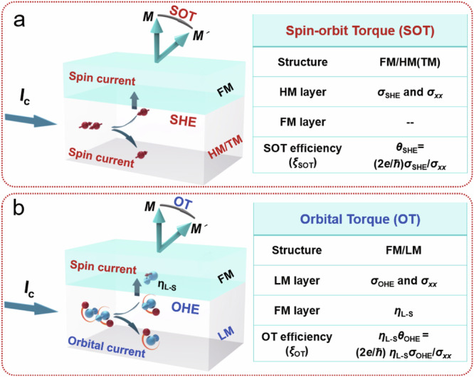
a Schematic of the SOT system. Spin current generated from the heavy metals (HMs) or topological materials (TMs) due to the spin Hall effect (SHE) is injected into the adjacent ferromagnetic (FM) layer, exerting the SOT. The torque efficiency (ξSOT) of SOT is dominated by the spin Hall angle (θSHE) of the HMs or TMs. b Schematic of the OT system. Orbital current originated from the light materials (LMs) due to the orbital Hall effect (OHE) is injected into the adjacent FM layer, then the orbital current is converted to spin current in the FM layer due to the orbital-to-spin conversion. This spin current exerts a torque on the magnetic moment M, which we call the OT. The torque efficiency (ξOT) of the OT is determined by not only the orbital Hall angle (θOHE) of the LMs but also the spin-orbit conversion coefficient (ηL-S) of the FM layer. The e, ћ, and σxx are the charge of an electron, reduced Planck constant, and electrical conductivity of SHM and OHM, respectively.
Orbital torque efficiency
To experimentally investigate the ξOT as well as the influence from the PMA FM layer, we designed the samples with the Zr OHM and two kinds of PMA FM layers, [Co/Pt]3 and CFB/Gd/CFB PMA samples. The samples, Zr (10.0 nm)/[Co/Pt]3 and Zr (10.0 nm)/CFB/Gd/CFB, as well as the W SHM reference samples with the identical samples, were deposited on the Al2O3 (0001) single crystal substrates and the thermal-oxide Si/SiO2 (300 nm) substrates, respectively (see the sample preparation of the “Methods”). To characterize the crystal structure of the Zr layer, the 50-nm-thick Zr thin films were prepared with the same experimental condition as the Zr/FM heterostructures and then measured by X-ray diffraction. The polycrystalline structure with the (001) orientation is observed with the (002) and (004) peaks, as shown in Supplementary Fig. 1a, b (see Supplementary Note 1). Meanwhile, the surface morphology of the Al2O3/Zr (10.0 nm)/[Co (0.3 nm)/Pt (0.7 nm)]3 and Si/SiO2/Zr (10.0 nm)/CFB (0.8 nm)/Gd (1.2 nm)/CFB (1.1 nm) samples were characterized by atomic force microscope (AFM). We found that the Zr (10.0 nm)/[Co/Pt]3 and Zr (10.0 nm)/CFB/Gd/CFB samples show a very smooth surface with an average surface roughness ~ 0.139 nm and 0.144 nm, respectively.
Subsequently, the torque efficiency was determined by the harmonic Hall voltage measurement, which can quantitatively characterize the effective magnetic field originating from the SHE or OHE induced by the alternating current (a.c.)47. The samples of Zr (10.0 nm)/[Co/Pt]3, Zr (10.0 nm)/CFB/Gd/CFB, W (5.0 nm)/[Co/Pt]3 and W (5.0 nm)/CFB/Gd/CFB were patterned into Hall bar devices (140 µm × 16 µm) and characterized the torque efficiency through the harmonic Hall voltage measurements. The results are presented in Fig. 2 and Supplementary Fig. 2. The schematic of the torque efficiency measurement for Zr OHM and W SHM is shown in Fig. 2a, d and Supplementary Fig. 2a, d, respectively. In these configurations, the alternating current is applied along the x-axis by sweeping the in-plane external magnetic field (Hext) along the x-axis and y-axis to character the longitudinal effective magnetic field (HL) and transverse effective magnetic field (HT) resulting from the current-induced torque. The HL and HT values can be obtained by the equations below47–52:
| 1 |
| 2 |
| 3 |
| 4 |
where the Bx(y) is determined by the ratio between the slope of the second harmonic Hall voltage (V2ω) and the curvature of the first harmonic Hall voltage (Vω) versus Hext along x(y)-axes. The correction factor ξ is the ratio between the planar Hall resistance (RPHE) and the anomalous Hall resistance (RAHE). The symbol ± represents the magnetization direction, oriented either along +z or –z. We find that the Vω with the Hext can be well fitted by the parabolic function, suggesting that the samples are magnetically saturated and conform to the coherent rotation model during sweeping of the Hext. The V2ω exhibits a linear variation in response to the Hext, as shown in Fig. 2b, c, e, f and Supplementary Fig. 2b, c, e and f. The consistent sign of the slope in the longitudinal scheme for positive and negative magnetized states, along with the inverse sign of the slope in the transverse scheme, suggests the presence of the torque originated from the OHE of Zr and SHE of W. The damping-like torque efficiency (ξDL) and field-like torque efficiency (ξFL) can be extracted using the equation of (see Supplementary Note 2)47,52,53. MS and tF are the saturation magnetization and the thickness of the FM layer, respectively. e is the charge of an electron, ℏ is the reduced Planck constant, μ0 is the permeability of the vacuum, and Je is the current density flowing through the Zr OHM or the W SHM. It is challenging to quantitatively calculate the contributions between the spin-orbit torque effect and the spin-orbit conversion effect for the [Co/Pt]3 and CoFeB/Gd/CFB layers. Thus for estimating the ξDL, we focus on determining the effective current density Je in the Zr OHM and W SHM without considering the contribution of current-induced SOT in the single [Co/Pt]3 and CFB/Gd/CFB FM layers. The ξOT,DL and ξOT,FL are estimated to be ~0.78 and ~0.39 for the Zr (10.0 nm)/[Co/Pt]3 sample but only ~0.04 and ~0.12 for the Zr (10.0 nm)/CFB/Gd/CFB sample. This larger field-like torque could originate from the orbital Rashba effect and some possible contributions (e.g., mixing conductance, backflow effect, swapping effect)53. This discrepancy suggests that the ηL-S of the FM layer plays a crucial role in the OHE. The fitted ξSOT,DL and ξSOT,FL are ~0.53 and ~0.15 for W (5.0 nm)/[Co/Pt]3 samples and ~0.35 and ~0.80 for the W (5.0 nm)/CFB/Gd/CFB sample, respectively, which is consistent with the reported values54,55. Additionally, the sign of ξOT,DL of the Zr (10.0 nm)/[Co/Pt]3 sample is consistent with the W (5.0 nm)/[Co/Pt]3 sample because the positive sign of σOHE of Zr and negative ηL-S of [Co/Pt]3 should lead to the negative ξOT of Zr (10.0 nm)/[Co/Pt]356,57, consistent with the negative θSHE of W54,55. We also summarize the ξOT as a function of the σOHE for the OHMs with different FM layers26,33–38,41–46, as plotted in Fig. 2g. To the best of our knowledge, the value of the ξOT of Zr (10.0 nm)/[Co/Pt]3 in our work is the largest one so far, suggesting that the [Co/Pt]3 PMA layer has a large ηL-S and can be selected as a dominant FM layer for conversion of orbital current to spin current.
Fig. 2. Orbital torque efficiency.

a Schematic of the longitudinal orbital-torque induced effective field measurement for the Zr (10.0 nm)/FM samples, where the FM layer includes [Co (0.3 nm)/Pt (0.7 nm)]3 and CFB (0.8 nm)/Gd (1.2 nm)/CFB (1.1 nm). Ia.c and HL are the applied current along the x-axis and generated longitudinal effective magnetic field by orbital Hall effect (OHE). b, c The first harmonic voltage (Vω) vs. in-plane longitudinal external magnetic field (Hext) and the second harmonic voltage (V2ω) vs. Hext for the Zr (10.0 nm)/[Co (0.3 nm)/Pt (0.7 nm)]3 and Zr (10.0 nm)/CFB (0.8 nm)/Gd (1.2 nm)/CFB (1.1 nm) samples, respectively. The damping-like orbital torque efficiency (ξOT, DL) is estimated to be ~0.78 and ~0.04 for Zr/[Co/Pt]3 and Zr/CFB/Gd/CFB samples, respectively. d Schematic of the longitudinal spin-orbit torque induced effective field measurement for the W (5.0 nm)/FM samples, where the FM layer includes [Co (0.3 nm)/Pt (0.7 nm)]3 and CFB (0.8 nm)/Gd (1.2 nm)/CFB (1.1 nm). Ia.c and HL are the applied current along the x-axis and generated longitudinal effective magnetic field by spin Hall effect (SHE). e, f The first harmonic voltage (Vω) vs. in-plane longitudinal external magnetic field (Hext) and the second harmonic voltage (V2ω) vs. Hext for the W (5.0 nm)/[Co (0.3 nm)/Pt (0.7 nm)]3 and W (5.0 nm)/CFB (0.8 nm)/Gd (1.2 nm)/CFB (1.1 nm) samples, respectively. The damping-like spin-orbit torque efficiency (ξSOT, DL) is estimated to be ~0.53 and ~0.35 for W/[Co/Pt]3 and W/CFB/Gd/CFB samples, respectively. g The summary of the orbital torque efficiency (ξOT) as a function of orbital Hall conductivity (σOHE) for the OHMs.
Orbital torque switching
To further investigate the efficiency of the magnetization switching through the Zr OHM and W SHM, we prepared the Zr (10.0 nm)/[Co/Pt]3 samples and a reference sample with the structure of W (5.0 nm)/[Co/Pt]3. Figure 3a, c show the RAHE as functions of the out-of-plane Hext for the [Co/Pt]3 samples deposited on the Zr OHM and W SHM, respectively. The square RAHE vs. Hext loops indicate their excellent PMA properties. Magnetometry was also utilized to confirm the PMA of the [Co/Pt]3 sample (see Supplementary Note 3 and Supplementary Fig. 3). Subsequently, the samples were patterned into the Hall bar devices, and the current-induced orbital/spin-torque magnetization switching was performed under an in-plane Hext along the current direction, ranging from ±100 Oe to ±500 Oe with the 20-ms write direct-current (d.c.) pulse width. Figure 3b and Supplementary Fig. 4a illustrate the magnetization switching of the Zr (10.0 nm)/[Co/Pt]3 sample. Complete magnetization switching is observed with the assistance of the positive and negative in-plane Hext at Js ~ 2.6 × 10⁶ A/cm2. Furthermore, upon reversing the applied in-plane field direction, the polarity of the current-induced switching loop also reverses, excluding the thermal effect. Since the RAHE values obtained by the field sweeping and current sweeping are similar, we conclude that the full magnetization switching of the [Co/Pt]3 samples has been achieved. However, for the W (10.0 nm)/[Co/Pt]3 samples, as shown in Fig. 3d and Supplementary Fig. 4b, only partial magnetization switching occurs with the assistance of the positive and negative in-plane Hext at Js ~ 6.6 × 10⁶ A/cm2 compared to the RAHE values obtained by field sweeping. Complete magnetization switching cannot be observed even at high Js. It is noteworthy that the Js of Zr (10.0 nm)/[Co/Pt]3 (Js ∼ 2.6 × 10⁶ A/cm2) is comparable with or better than that of W (5.0 nm)/[Co/Pt]3 (Js ~ 6.6 × 10⁶ A/cm2), suggesting that the [Co/Pt]3 samples with large ηL-S can more efficiently convert orbital current to spin current through the Zr OHM.
Fig. 3. Orbital torque switching.

a, c The AHE loops of Zr (10.0 nm)/[Co (0.3 nm)/Pt (0.7 nm)]3 and W (5.0 nm)/[Co (0.3 nm)/Pt (0.7 nm)]3 samples, respectively. b, d Current-induced orbital torque switching for Zr (10.0 nm)/[Co (0.3 nm)/Pt (0.7 nm)]3 and W (5.0 nm)/[Co (0.3 nm)/Pt (0.7 nm)]3 samples with the fixed in-plane Hext = +200 Oe and −200 Oe, respectively. The Js of Zr (10.0 nm)/[Co (0.3 nm)/Pt (0.7 nm)]3 is as low as Js ∼ 2.6 × 10⁶ A/cm2, which is lower than that of W (5.0 nm)/[Co (0.3 nm)/Pt (0.7 nm)]3 (Js ~ 6.6 × 10⁶ A/cm2). e, g The AHE loops of the Zr (10.0 nm)/CFB (0.8 nm)/Gd (1.2 nm)/CFB (1.1 nm) and W (5.0 nm)/CFB (0.8 nm)/Gd (1.2 nm)/CFB (1.1 nm) samples, respectively. f, h Current-induced orbital torque switching of the Zr (10.0 nm)/CFB (0.8 nm)/Gd (1.2 nm)/CFB (1.1 nm) and W (5.0 nm)/CFB (0.8 nm)/Gd (1.2 nm)/CFB (1.1 nm) samples with the fixed in-plane Hext = +200 Oe and −200 Oe, respectively. The Js of Zr (10.0 nm)/CFB (0.8 nm)/Gd (1.2 nm)/CFB (1.1 nm) is ∼4.9 × 10⁶ A/cm2, which is higher than that of W (5.0 nm)/CFB/Gd/CFB (Js ~ 1.6 × 10⁶ A/cm2).
Subsequently, the other PMA CFB/Gd/CFB sample is utilized to study the current-induced orbital/spin-torque magnetization switching through the Zr OHM and W SHM under the same measured condition. Figure 3e, g and Supplementary Fig. 5a, b display the square RAHE vs. Hext and M/MS vs. Hext loops of the Zr (10.0 nm)/CFB/Gd/CFB and W (5.0 nm)/CFB/Gd/CFB samples, respectively, confirming their good PMA properties. Figure 3f and Supplementary Fig. 6a show the magnetization switching of the Zr (10.0 nm)/CFB/Gd/CFB sample with the assistance of both the positive and negative in-plane Hext at Js ~ 4.9 × 10⁶ A/cm2. We note that it is a partial magnetization switching, the possible reason could be the relatively small ξOT,DL ~ 0.04. However, for the W (5.0 nm)/CFB/Gd/CFB sample, as shown in Fig. 3h and Supplementary Fig. 6b, the full magnetization switching occurs with the assistance of both the positive and negative in-plane Hext at Js ~ 1.6 × 10⁶ A/cm2. Due to the relatively larger θSHE, the Js is lower than that of the Ta (5.0 nm)/CFB/Gd/CFB sample with Js ~ 2.0 × 10⁷ A/cm in our previous work4. Although the Zr layers deposited on the Al2O3 and Si/SiO2 substrates show a similar polycrystalline structure with the predominant (001) orientation, the capability of the magnetization switching is different. The main reason will be the contribution of the PMA FM layers, [Co/Pt]3 and CFB/Gd/CFB.
Spin-orbit correlation function calculation
One of the critical factors influencing the torque efficiency of OHE is the ηL-S of the FM materials, as indicated by the aforementioned harmonic results and orbital torque switching, which describes the orbital-to-spin current conversion efficiency. To gain a deeper understanding of the intrinsic relationship between the torque efficiency, OT switching, and the ηL-S of the FM layer in the OHE system, we designed the CoPt2 and Co2Fe6 structures to represent the experimental [Co/Pt]3 and CFB/Gd/CFB samples, respectively, and conducted full electronic simulations to calculate their spin-orbit correlation function based on density functional theory (see methods for calculation details). Figure 4a, b show the side views for CoPt2 and Co2Fe6 structures, respectively, with similar thicknesses as the experiments.
Fig. 4. Theoretical calculation of spin-orbit correlation function and projected band structure.

a The schematic of the designed CoPt2 structure and the calculated result of the spin-orbit correlation function. Co and Pt atoms are colored dark blue and light gray, respectively. b The schematic of the designed Co2Fe6 structure and the calculated result of the spin-orbit correlation function. Co and Fe atoms are colored dark blue and yellow, respectively. The color represents the correlation for each eigenstate, in which red and blue denote strong positive and negative correlations, respectively. c The projected band structure of CoPt2 with SOC with different d states of Pt is highlighted by different colors. d Analogous to c, but for the Fe d orbitals in Co2Fe6 with SOC.
The magnitude of ηL-S is roughly proportional to the 27. The band-resolved spin-orbit correlation function was calculated after constructing the effective Hamiltonian using the Wannier90 package (see Supplementary Note 4 and Supplementary Figs. 7–10). The results are summarized in Fig. 4, where red and blue colored areas denote strong positive and negative correlations, respectively. In Fig. 4a for the CoPt2 structure, multiple spin-orbit correlation hotspots below the Fermi level (EF) (e.g., along the Γ-X and Γ-M line) lead to a large ηL-S, indicating the strong orbital-to-spin conversion efficiency. In addition, the magnetic moments are primarily located on the Co atoms (~2.1 μB) with small contributions from the Pt atoms (~0.3 μB). The magnetic moment of Pt derives from a strong proximity effect between the Co and Pt, resulting in the substantial exchange splitting of Pt (spin-polarized band structure in Supplementary Fig. 11). By checking the wave function, we find that with SOC is mainly contributed by d states of Co and d states of Pt in the CoPt2 structure, as shown in Supplementary Fig. 12a, and the majority of the spin-orbit correlation hotspots are mainly contributed by the Pt bands. On the contrary, for the Co2Fe6 structure, we observe limited spin-orbit correlation hotspots below the EF, indicating much weaker correlation strength compared to the CoPt2 structure, as shown in Fig. 4b. By checking the wave function, we can see that the d states of Co and Fe in the Co2Fe6 structure, especially the majority atom Fe, play a leading role in contributing to with SOC, as shown in Supplementary Fig. 12b. To better understand the differences in the values between the CoPt2 and Co2Fe6 systems, we have examined the orbital hybridization of the d states in Pt and Fe atoms, as illustrated in Fig. 4c, d, respectively. In the CoPt2 system shown in Fig. 4c, significant overlap of d orbitals is observed along the Γ-X and M-Γ paths, indicating extensive orbital hybridization. This enhances the richness of the L operator matrix, thereby leading to higher values. Conversely, along the X-M path, each band predominantly exhibits a single orbital character, correlating with lower values. A similar analysis applies to the Co2Fe6 system, where areas of pronounced orbital hybridization, particularly around the Γ point and along the X-M and M-Γ paths below the Fermi level, coincide with the hotspots. Overall, the extent of orbital hybridization in Pt within the CoPt2 system is greater than that of Fe in the Co2Fe6 system, thereby substantiating the larger observed in CoPt2 relative to Co2Fe6, even in different configurations of the CoPt2 and Co2Fe6 structures (Supplementary Fig. S9). The values of ηL-S for CoPt2 and Co2Fe6 structures are calculated as 1.161 and 0.171 (more details in Supplementary Note 4), respectively, with the value for the [Co/Pt]n system significantly larger than that of the CoFeB system. These results align with our experimental results, revealing a relatively high ξOT of the Zr/CoPt2 structure compared to the Zr/Co2Fe6 structure. This underscores the significance of the ηL-S of the FM materials in the OHE devices, which provides another pathway for improving the orbital torque efficiency.
Discussion
To summarize, we have investigated the ξOT and magnetization switching of the PMA materials (i.e., [Co/Pt]3 and CFB/Gd/CFB) through the OT of the Zr OHM. The largest ξOT ~ 0.78 was obtained in Zr/[Co/Pt]3 due to both the large OHE of Zr and the strong spin-orbit correlation function of the [Co/Pt]3 structure. Furthermore, the switching of the PMA materials with the large ηL-S via the Zr OHM (Js ∼ 2.6 × 10⁶ A/cm2) is much more efficient than that of the PMA materials with the small ηL-S via the Zr OHM (Js ~ 4.9 × 10⁶ A/cm2). These experimental results have also been confirmed through the spin-orbit correlation function calculation, where the CoPt2 structure possesses stronger spin-orbit correlation function strength than that of the Co2Fe6 structure. Our results highlight the crucial relationship between the ξOT and the spin-orbit correlation function of the PMA materials and establish a direct link between the magnetization switching and the properties of the PMA FM layer.
Our experimental and calculated results carry important implications for developing efficient orbitronic memory and logic devices. Previous studies about SOT devices have only emphasized the exploration of strong SOC SHMs, while recent investigations about the orbital torque devices have focused on the ξOT values of the OHMs. Our findings not only demonstrate the OT switching of the PMA materials but also elucidate the physical mechanism to realize the efficient OT switching by engineering the PMA materials with large ηL-S. Moreover, we note that the PMA materials with large ηL-S enable the enhancement of the ξOT and switching efficiency, which, however, could be further optimized, such as with a low damping constant. Normally, the strong spin-orbit coupling of the FM layer will contribute to the relatively larger damping constant. Therefore, we need to engineer the PMA materials (e.g. FePd) which have both large ηL-S and low damping constant, or synthetic antiferromagnetic structures in which one PMA layer with large ηL-S (e.g. [Co/Pd]n or [Co/Pt]n) and the other PMA layer with small ηL-S and low damping constant (e.g. CoFeB). The method to experimentally evaluate the accurate value of the ηL-S of the PMA materials also needs to be explored. Furthermore, it is challenging to quantitatively separate SOT and OT contributions with the strong SOC FM layer. Consequently, our study offers a design guideline for memory and logic device optimization that may overcome the difficulties of SOT devices and explore industry-compatible orbitronic devices with excellent performance.
Methods
Sample preparation and characterization
All the samples were prepared by utilizing an ultrahigh vacuum magnetron sputtering system with a base pressure lower than 5.0×10⁻⁸ Torr. The Zr (50.0 nm), Zr (10.0 nm)/[Co (0.3 nm)/Pt (0.7 nm)]3 and W (5.0 nm)/[Co (0.3 nm)/Pt (0.7 nm)]3 samples were deposited on the Al2O3 (0001) single crystal substrates, and the Zr (50.0 nm), Zr (10.0 nm)/CFB (0.8 nm)/Gd (1.2 nm)/CFB (1.1 nm)/MgO (2.0 nm)/W (2.0 nm), and W (5.0 nm)/CFB (0.8 nm)/Gd (1.2 nm)/CFB (1.1 nm)/MgO (2.0 nm)/W (2.0 nm) samples were deposited on the Si/SiO2 substrates. During the deposition process, the pressure of the Ar gas was 3 mTorr. The Zr layer on the Al2O3 substrate was prepared with the substrate heating at 300 °C, and the Zr layer on the Si/SiO2 substrate was prepared with the post-annealing at 300 °C. The deposition rates of Zr, W, CFB, Gd, MgO, Co, and Pt are 0.25, 0.14, 0.16, 0.80, 0.05, 0.20, and 0.17 Å/s, respectively, with the corresponding sputtering power of 40, 30, 50, 50, 150, 50, and 15 W. The crystal structure and quality of the Zr (50.0 nm) thin films on Al2O3 and Si/SiO2 substrates are characterized by X-ray diffraction (XRD), whose surface roughness and uniformity are measured by atomic force microscope (AFM). The M-H curves were measured by a vibrating sample magnetometer (VSM).
Device patterning and testing
The samples were patterned into Hall bar devices by using standard photolithography and an Ar ion milling technique. The samples were coated with photoresist using spin-coating, baked at 85 °C for 60 s, exposed to UV light for 3.2 s, developed with AZ developer for 8 s, and then subjected to Ar ion milling for 5.5 min to achieve the desired Hall bar pattern. After removing the residual photoresist by ultrasound, a second photolithography process is carried out to obtain the contact pattern. Ti (10.0 nm)/Pt (100.0 nm) were deposited as the contact electrodes, which were made by d.c. sputtering and lift-off technology.
For the harmonic Hall voltage measurements, the devices were first magnetized to a saturation state by applying a large magnetic field (±1.6 T) perpendicular to the film plane. A sinusoidal a.c. current with an amplitude of 8 mA or 16 mA and frequency of 13.7 Hz was applied by a Keithley 6221 source meter, and the first harmonic Hall voltages (Vω) and second harmonic Hall voltages (V2ω) were simultaneously measured through two Stanford SR830 lock-in amplifiers while sweeping Hext along or transversely to the current direction. The RAHE–H curves were obtained by using a Keithley 2400 source meter. The RAHE–Js curves were detected by using Keithley 6221 and 2182 A with a fixed magnetic field of ±100 Oe ~ ±500 Oe along the current direction, where the symbol “+” represents the fixed magnetic field parallel to the current direction, while “-” denotes the fixed magnetic field antiparallel to the current direction. The current density above was calculated by considering the shunting effect of the FM layer in all devices. All the measurements were performed at room temperature.
Theoretical calculations
CoPt2 and Co2Fe6 structures along the [001] direction were simulated using the face-centered cubic and body-centered cubic phases, respectively. We performed first-principle calculations based on the density functional theory (DFT) as implemented in the Vienna ab initio simulation package (VASP)58,59, which is treated by the projector-augmented plane-wave (PAW) method by utilizing a plane-wave basis set60. The exchange-correlation potential terms were considered at the level of generalized gradient approximation (GGA) within the scheme of Perdew-Burke-Ernzerhof (PBE) functional61. The plane-wave cutoff energy is chosen as 450 eV, and we sample the Brillouin zone on 9 × 9 × 1 and 12 × 12 × 1 regular mesh for the self-consistent calculations of CoPt2 and Co2Fe6, respectively. The geometric optimizations were performed without any constraint with a convergence criterion of 10-6 eV. To avoid the interaction between the layers along the z direction, we introduced a vacuum layer with a thickness of 15 Å.
To investigate the spin-orbit correlation for Co2Fe6 and CoPt2, which gives the orbital to spin conversion for the orbital Hall current (i.e., 21,62, the Kohn-Sham wave functions were projected onto highly symmetric atomic orbitals like Wannier functions (specifically, Co-d and Pt-s, p, d orbitals for CoPt2, Co-s, p, d and Fe-s, p, d orbitals for Co2Fe6) and we constructed tight-binding Hamiltonians utilizing the WANNIER90 package63,64. The obtained Hamiltonian is further applied to obtain the spin-orbit correlation with the crystal momentum k in the band by computing . refers to orbital angular momentum, which is treated as an atomic angular momentum operator. is the spin angular momentum operator, and the direct product of these two operators will yield the matrix.
Supplementary information
Source data
Acknowledgements
This work was supported by the National Key R&D Program of China (2022YFA1204003 (Y.J.)) and the National Natural Science Foundation of China (Grant Nos. 52271240 (D.L.Z.), U23A20551 (D.L.Z.), 12204037 (W.J.), 52061135205 (Y.J.), 51971023 (Y.J.), 51927802 (Y.J.)). D.L.Z gratefully acknowledges the research funding provided by the Cangzhou Institute of Tiangong University (Grant No. TGCYY-F-0201 (D.L.Z.)). P.W. gratefully acknowledges this work was supported by the Hebei Natural Science Foundation (Grant No. E2023110012 (P.W.)).
Author contributions
Y.H.Y., P.W., J.L.C., and D.L.Z. contributed equally to this work. D.L.Z initialized and conceived this work. Y.J. coordinated and supervised the project. D.L.Z., Y.H.Y., and P.W. conceived the experiments and designed all the samples. Y.H.Y. prepared all the samples, Y.H.Y., T.W., W.S.Y., and C.C. patterned the Hall bar devices and carried out the current-induced orbital/spin-torque magnetization switching experiments. C.P., S.H., and X.P.Q. carried out the second harmonic measurements. J.L.C., W.J., and Y.G.Y. performed the first-principles calculations. L.J.Z. conducted the crystalline characterizations. Y.L. and W.H.W. help analyze the experimental data. D.L.Z., Y.H.Y., and P.W. wrote the manuscript. All the authors discussed the results and commented on the manuscript.
Peer review
Peer review information
Nature Communications thanks Anmol Mahendra, Fen Xue and the other anonymous reviewer(s) for their contribution to the peer review of this work. A peer review file is available.
Data availability
The authors declare that the data supporting the findings of this study are available within the main text and Supplementary Information files. Source data are provided in this paper.
Competing interests
The authors declare no competing interests.
Footnotes
Publisher’s note Springer Nature remains neutral with regard to jurisdictional claims in published maps and institutional affiliations.
These authors contributed equally: Yuhe Yang, Ping Wang, Jiali Chen, Delin Zhang.
Contributor Information
Delin Zhang, Email: zhangdelin@tiangong.edu.cn.
Wei Jiang, Email: wjiang@bit.edu.cn.
Yong Jiang, Email: yjiang@tiangong.edu.cn.
Supplementary information
The online version contains supplementary material available at 10.1038/s41467-024-52824-2.
References
- 1.Sinova, J. et al. Spin Hall effects. Rev. Mod. Phys.87, 1213 (2015). [Google Scholar]
- 2.Song, C. et al. Spin-orbit torques: materials, mechanisms, performances, and potential applications. Prog. Mater. Sci.118, 100761 (2021). [Google Scholar]
- 3.Mellnik, A. R. et al. Spin-transfer torque generated by a topological insulator. Nature511, 449–451 (2014). [DOI] [PubMed] [Google Scholar]
- 4.DC, M. et al. Room-temperature high spin-orbit torque due to quantum confinement in sputtered BixSe(1-x) films. Nat. Mater.17, 800–807 (2018). [DOI] [PubMed] [Google Scholar]
- 5.Zhang, D. L. et al. Robust negative longitudinal magnetoresistance and spin-orbit torque in sputtered Pt3Sn and Pt3SnxFe1-x topological semimetal. Nat. Commun.14, 4151 (2023). [DOI] [PMC free article] [PubMed] [Google Scholar]
- 6.Soumyanarayanan, A., Reyren, N., Fert, A. & Panagopoulos, C. Emergent phenomena induced by spin-orbit coupling at surfaces and interfaces. Nature539, 509–517 (2016). [DOI] [PubMed] [Google Scholar]
- 7.Guo, Z. et al. Spintronics for energy-efficient computing: an overview and outlook. Proc. IEEE109, 1398–1417 (2021). [Google Scholar]
- 8.Bajaj, A., Gupta, R., Tokatly, I. V., Sanvito, S. & Droghetti, A. Ab initio transport theory for the intrinsic spin Hall effect applied to 5d metals. Phys. Rev. B109, 195132 (2024). [Google Scholar]
- 9.Zhu, L. Switching of perpendicular magnetization by spin-orbit torque. Adv. Mater.35, 2300853 (2023). [DOI] [PubMed] [Google Scholar]
- 10.Shao, Q. et al. Roadmap of spin-orbit torques. IEEE Trans. Magn.57, 1–39 (2021). [DOI] [PMC free article] [PubMed] [Google Scholar]
- 11.Han, X., Wang, X., Wan, C., Yu, G. & Lv, X. Spin-orbit torques: materials, physics, and devices. Appl. Phys. Lett.118, 120502 (2021). [Google Scholar]
- 12.Manchon, A. et al. Current-induced spin-orbit torques in ferromagnetic and antiferromagnetic systems. Rev. Mod. Phys.91, 035004 (2019). [Google Scholar]
- 13.Hall, E. H. On a new action of the magnet on electric currents. Am. J. Math.2, 287–292 (1879). [Google Scholar]
- 14.Kang, M.-G. et al. Electric-field control of field-free spin-orbit torque switching via laterally modulated Rashba effect in Pt/Co/AlOx structures. Nat. Commun.12, 7111 (2021). [DOI] [PMC free article] [PubMed] [Google Scholar]
- 15.Mishra, R. et al. Electric-field control of spin accumulation direction for spin-orbit torques. Nat. Commun.10, 248 (2019). [DOI] [PMC free article] [PubMed] [Google Scholar]
- 16.Wang, M. et al. Field-free spin-orbit torque switching via out-of-plane spin-polarization induced by an antiferromagnetic insulator/heavy metal interface. Nat. Commun.14, 2871 (2023). [DOI] [PMC free article] [PubMed] [Google Scholar]
- 17.Khang, N. H. D. et al. A conductive topological insulator with large spin Hall effect for ultralow power spin-orbit torque switching. Nat. Mater.17, 808–813 (2018). [DOI] [PubMed] [Google Scholar]
- 18.Shi, S. et al. All-electric magnetization switching and Dzyaloshinskii-Moriya interaction in WTe2/ferromagnet heterostructures. Nat. Nanotechnol.14, 945–949 (2019). [DOI] [PubMed] [Google Scholar]
- 19.Ramaswamy, R. et al. Spin orbit torque driven magnetization switching with sputtered Bi2Se3 spin current source. J. Phys. D Appl. Phys.52, 224001 (2019). [Google Scholar]
- 20.Bernevig, B. A., Hughes, T. L. & Zhang, S. C. Orbitronics: the intrinsic orbital current in p-doped silicon. Phys. Rev. Lett.95, 066601 (2005). [DOI] [PubMed] [Google Scholar]
- 21.Kontani, H., Tanaka, T., Hirashima, D. S., Yamada, K. & Inoue, J. Giant orbital Hall effect in transition metals: origin of large spin and anomalous Hall effects. Phys. Rev. Lett.102, 016601 (2009). [DOI] [PubMed] [Google Scholar]
- 22.Go, D., Jo, D., Kim, C. & Lee, H. W. Intrinsic spin and orbital Hall effects from orbital texture. Phys. Rev. Lett.121, 086602 (2018). [DOI] [PubMed] [Google Scholar]
- 23.Jo, D., Go, D. & Lee, H.-W. Gigantic intrinsic orbital Hall effects in weakly spin-orbit coupled metals. Phys. Rev. B98, 214405 (2018). [Google Scholar]
- 24.Han, S., Lee, H. W. & Kim, K. W. Orbital dynamics in centrosymmetric systems. Phys. Rev. Lett.128, 176601 (2022). [DOI] [PubMed] [Google Scholar]
- 25.Go, D. et al. Long-range orbital torque by momentum-space hotspots. Phys. Rev. Lett.130, 246701 (2023). [DOI] [PubMed] [Google Scholar]
- 26.Choi, Y. G. et al. Observation of the orbital Hall effect in a light metal Ti. Nature619, 52–56 (2023). [DOI] [PubMed] [Google Scholar]
- 27.Lee, D. et al. Orbital torque in magnetic bilayers. Nat. Commun.12, 6710 (2021). [DOI] [PMC free article] [PubMed] [Google Scholar]
- 28.Hamdi, A. E. et al. Observation of the orbital inverse Rashba-Edelstein effect. Nat. Phys.19, 1855–1860 (2023). [Google Scholar]
- 29.Seifert, T. S. et al. Time-domain observation of ballistic orbital-angular-momentum currents with giant relaxation length in tungsten. Nat. Nanotechnol.18, 1132–1138 (2023). [DOI] [PMC free article] [PubMed] [Google Scholar]
- 30.Wang, P. et al. Inverse orbital Hall effect and orbitronic terahertz emission observed in the materials with weak spin-orbit coupling. npj Quantum Mater. 8, 28 (2023). [Google Scholar]
- 31.Ding, S. et al. Harnessing Orbital-to-spin conversion of interfacial orbital currents for efficient spin-orbit torques. Phys. Rev. Lett.125, 177201 (2020). [DOI] [PubMed] [Google Scholar]
- 32.Ding, S. et al. Observation of the orbital Rashba-Edelstein magnetoresistance. Phys. Rev. Lett.128, 067201 (2022). [DOI] [PubMed] [Google Scholar]
- 33.Fukunaga, R. et al. Orbital torque originating from orbital Hall effect in Zr. Phys. Rev. Res.5, 023054 (2023). [Google Scholar]
- 34.Hayashi, H. et al. Observation of long-range orbital transport and giant orbital torque. Commun. Phys.6, 32 (2023). [Google Scholar]
- 35.Lee, S. et al. Efficient conversion of orbital Hall current to spin current for spin-orbit torque switching. Commun. Phys.4, 234 (2021). [Google Scholar]
- 36.Guo, Y. et al. Large damping-like torque and efficient current-induced magnetization reversal in Ti/Tb-Co/Cr structures. Appl. Phys. Lett.123, 022408 (2023). [Google Scholar]
- 37.Zhang, J. et al. The giant orbital Hall effect in Cr/Au/Co/Ti multilayers. Appl. Phys. Lett.121, 172405 (2022). [Google Scholar]
- 38.Zheng, Z. C. et al. Magnetization switching driven by current-induced torque from weakly spin-orbit coupled Zr. Phys. Rev. Res.2, 013127 (2020). [Google Scholar]
- 39.Lyalin, I., Alikhah, S., Berritta, M., Oppeneer, P. M. & Kawakami, R. K. Magneto-optical detection of the orbital Hall effect in Chromium. Phys. Rev. Lett.131, 156702 (2023). [DOI] [PubMed] [Google Scholar]
- 40.Sala, G., Wang, H., Legrand, W. & Gambardella, P. Orbital Hanle magnetoresistance in a 3d transition metal. Phys. Rev. Lett.131, 156703 (2023). [DOI] [PubMed] [Google Scholar]
- 41.Sala, G. & Gambardella, P. Giant orbital Hall effect and orbital-to-spin conversion in 3d, 5d, and 4f metallic heterostructures. Phys. Rev. Res.4, 033037 (2022). [Google Scholar]
- 42.Dutta, S. & Tulapurkar, A. A. Observation of nonlocal orbital transport and sign reversal of damping like torque in Nb/Ni and Ta/Ni bilayers. Phys. Rev. B106, 184406 (2022). [Google Scholar]
- 43.Liu, F., Liang, B., Xu, J., Jia, C. & Jiang, C. Giant efficiency of long-range orbital torque in Co/Nb bilayers. Phys. Rev. B107, 054404 (2023). [Google Scholar]
- 44.Bose, A. et al. Detection of long-range orbital-Hall torques. Phys. Rev. B107, 134423 (2023). [Google Scholar]
- 45.Fukunaga, R., Haku, S., Gao, T., Hayashi, H. & Ando, K. Impact of crystallinity on orbital torque generation in ferromagnets. Phys. Rev. B109, 144412 (2024). [Google Scholar]
- 46.Gupta, R. et al. Harnessing orbital Hall effect in spin-orbit torque MRAM. Preprint at http://arxiv.org/abs/2404.02821 (2024).
- 47.Hayashi, M. et al. Quantitative characterization of the spin-orbit torque using harmonic Hall voltage measurements. Phys. Rev. B89, 144425 (2014). [Google Scholar]
- 48.Tang, M. et al. Bulk spin torque‐driven perpendicular magnetization switching in L10 FePt single layer. Adv. Mater.32, 2002607 (2020). [DOI] [PubMed] [Google Scholar]
- 49.Kim, J. et al. Layer thickness dependence of the current-induced effective field vector in Ta|CoFeB|MgO. Nat. Mater.12, 240–245 (2013). [DOI] [PubMed] [Google Scholar]
- 50.Garello, K. et al. Symmetry and magnitude of spin-orbit torques in ferromagnetic heterostructures. Nat. Nanotech.8, 587–593 (2013). [DOI] [PubMed] [Google Scholar]
- 51.Yun, S. J., Park, E.-S., Lee, K.-J. & Lim, S. H. Accurate analysis of harmonic Hall voltage measurement for spin-orbit torques. NPG Asia Mater.9, e449–e449 (2017). [Google Scholar]
- 52.Wang, X. et al. Large field-like spin-orbit torque and enhanced magnetization switching efficiency utilizing amorphous Mo. Nano Lett.24, 6931–6938 (2024). [DOI] [PubMed] [Google Scholar]
- 53.Huang, Q. et al. Current-induced magnetization switching in light-metal-oxide/ferromagnetic-metal bilayers via orbital Rashba effect. Nano Lett.23, 11323–11329 (2023). [DOI] [PubMed] [Google Scholar]
- 54.Pai, C. F. et al. Spin transfer torque devices utilizing the giant spin Hall effect of tungsten. Appl. Phys. Lett.101, 122404 (2012). [Google Scholar]
- 55.Mazraati, H. et al. Low operational current spin Hall nano-oscillators based on NiFe/W bilayers. Appl. Phys. Lett.109, 242402 (2016). [Google Scholar]
- 56.Xue, F. et al. Field-free spin-orbit torque switching assisted by in-plane unconventional spin torque in ultrathin [Pt/Co]n. Nat. Commun. 14, 3932 (2023). [DOI] [PMC free article] [PubMed]
- 57.Zhu, L. et al. Observation of strong bulk damping‐like spin‐orbit torque in chemically disordered ferromagnetic single layers. Adv. Funct. Mater.30, 2005201 (2020). [Google Scholar]
- 58.Kresse, G. & Furthmüller, J. Efficiency of ab-initio total energy calculations for metals and semiconductors using a Plane-Wave Basis set. Comput. Mater. Sci.6, 15 (1996). [DOI] [PubMed] [Google Scholar]
- 59.Kresse, G. & Hafner, J. Ab Initio molecular-dynamics simulation of the liquid-metal-amorphous-semiconductor transition in Germanium. Phys. Rev. B49, 14251 (1994). [DOI] [PubMed] [Google Scholar]
- 60.Blöchl, P. E. Projector augmented-wave method. Phys. Rev. B50, 17953 (1994). [DOI] [PubMed] [Google Scholar]
- 61.Perdew, J. P. et al. Atoms, Molecules, solids, and surfaces: Applications of the generalized gradient approximation for exchange and correlation. Phys. Rev. B46, 6671 (1992). [DOI] [PubMed] [Google Scholar]
- 62.Tanaka, T. et al. Intrinsic spin Hall effect and orbital Hall effect in 4d and 5d transition metals. Phys. Rev. B77, 165117 (2008). [Google Scholar]
- 63.Souza, I., Marzari, N. & Vanderbilt, D. Maximally localized Wannier functions for entangled energy bands. Phys. Rev. B65, 035109 (2001). [Google Scholar]
- 64.Marzari, N. & Vanderbilt, D. Maximally localized generalized Wannier functions for composite energy bands. Phys. Rev. B56, 12847 (1997). [Google Scholar]
Associated Data
This section collects any data citations, data availability statements, or supplementary materials included in this article.
Supplementary Materials
Data Availability Statement
The authors declare that the data supporting the findings of this study are available within the main text and Supplementary Information files. Source data are provided in this paper.