Abstract
Infinite 1D Ti–O rod-based metal–organic frameworks (MOFs) are promising photocatalysts for water splitting due to their high optical response and favourable photo-redox properties and stability, but have not been explored yet. In this study, three isoreticular porous 1D rod-based Ti-MOFs ZSTU-1, ZSTU-2 and ZSTU-3 are successfully constructed from infinite secondary building units (SBUs) and tritopic carboxylate linkers 4,4′,4″-nitrilotribenzoic acid (H3TCA), 1,3,5-tris(4-carboxyphenyl) benzene (H3BTB) and tris(4′-carboxybiphenyl)amine (H3BTCA), respectively. Their porosities systematically increase with the larger and longer organic linkers. The two MOFs ZSTU-1 and ZSTU-3 built from the triphenylamino-based ligands can absorb visible light, exhibiting much better photocatalytic performance than ZSTU-2 as shown by the H2 production rate of ZSTU-1 and ZSTU-3 being 3–4 times higher than that of ZSTU-2. The photocatalytic H2 production rates for ZSTU-1, ZSTU-2, and ZSTU-3 are 1060 μmol g−1 h−1, 350 μmol g−1 h−1 and 1350 μmol g−1 h−1, respectively. The extraordinary photocatalytic activity of ZSTU-3 is attributed to its visible light absorption, large surface area, and favorable charge separation.
Introduction
The global demand for clean and sustainable energy is huge.1,2 Photocatalytic water splitting by solar energy to generate H2 is one of the most promising solutions to provide clean and high-performance energy.3–5 Since visible light accounts for about 43% of solar energy compared with ultraviolet (UV) light which only contributes about 4%, visible-light-driven photocatalysis is more prominent for the efficient utilization of solar energy. Metal–organic frameworks (MOFs), as a new class of porous materials, have demonstrated promising applications in many fields.6–9 Their large surface areas, adjustable pore sizes, large flexibility in design and post-synthetic modification, and tunable opto-electronic properties have made them promising platforms for photocatalysis as well.10–18 Since the first report of MOFs for photocatalytic H2 evolution by Mori’s group,19 some MOFs have been demonstrated as photocatalytic H2 evolution catalysts with even better activity compared with their homogeneous counterparts, attributed to the enhanced catalyst stability and elongated life time of excited states resulting from efficient charge separation in MOF systems.20–25 One of the most important parameters to evaluate the photocatalytic activity of MOFs is the light-harvesting efficiency. In most MOF photocatalysts, organic ligands absorb light and then transfer electrons to inorganic nodes via a ligand-to-metal charge transfer (LMCT) process, generating photoactivity. It is highly desirable to use organic ligands that can absorb light in the visible region to construct MOFs as photocatalysts for higher light-harvesting efficiency. Most of the developed organic linkers with benzene backbones such as terephthalic acid (H2BDC), 1,3,5-benzenetricarboxylic acid (H3BTC) and 1,3,5-tris(4-carboxyphenyl) benzene (H3BTB) for the construction of MOFs can only absorb light in the UV region, so the resulting MOFs are not good photocatalysts in the visible region.26 Post-modification of linkers with functional groups such as –NH2 can extend the light absorption of MOFs to the visible light region to a certain degree.27–29 Triphenylamine and its derivatives are widely applied in organic solar cells and dye-sensitized solar cells (DSSCs), due to their strong electron-donating behavior and high charge transfer ability. Especially in DSSCs, triphenylamine-based dyes that are grafted onto TiO2 can efficiently sensitize TiO2 via charge injection after photoexcitation, demonstrating much better photovoltaic performance with record high efficiency.30,31 Furthermore, they can potentially absorb light in the visible region with high molar extinction coefficients and transfer the excited charges to metal clusters in DSSCs, so their MOFs might be promising photocatalysts in the visible region but have been rarely explored.32,33 Another requirement for MOFs as photocatalysts is the efficient charge separation. A longer lifetime of photo-excited charges usually leads to more efficient photocatalysis where redox reactions occur at photo-excited states.34 The alkyl chain substitution of the NH2 group in MIL-125-NH2 is believed to prolong the lifetime of the excited states of MIL-125-NH2, yielding higher photocatalytic reduction of CO2.35 Nevertheless, studies on improving the lifetime of the excited states of MOF photocatalysts are still lacking, and it is very necessary and important to realize novel systematical approaches to increase the lifetime of the charge separation state of photocatalytic MOFs in order to realize highly efficient photocatalysts in the visible region.
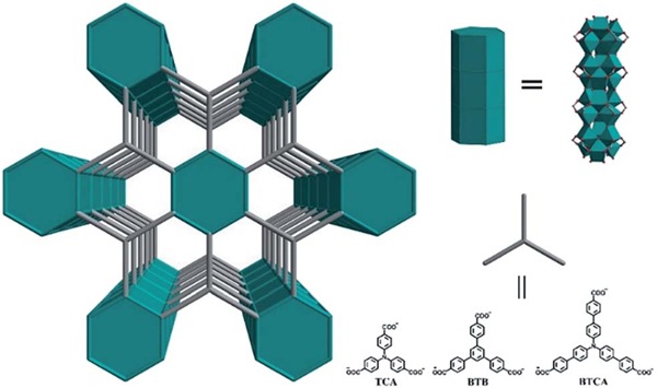
Other than the two above mentioned challenges, MOFs for photocatalytic H2 generation also greatly suffer due to their water instability. Among those stable MOFs which are typically constructed from high valent metal ions, Ti-MOFs are particularly interesting and important as efficient photocatalysts because of their high optical response and excellent photoredox properties originating from the unique Ti–O electronic structure.36–41 In fact, TiO2 might be the most studied photocatalyst because of its unique structure, and thus excellent charge separation and charge mobility.42 Studies have also shown that the electron mobility along the long axis in TiO2 nanotubes is much faster than that perpendicular to it, along the short axis,43 so it has been speculated that Ti-MOFs with 1D Ti–O rods might be even better than Ti-MOFs with discrete Ti–O clusters, though they have not been well explored yet.44 Herein we report a very simple approach to synthesize three isoreticular porous 1D rod-based Ti-MOFs from three tri-carboxylic acids 4,4′,4″-nitrilotribenzoic acid (H3TCA), 1,3,5-tris(4-carboxyphenyl) benzene (H3BTB) and tris(4′-carboxybiphenyl)amine (H3BTCA), denoted as ZSTU-1 , ZSTU stands for Zhejiang Sci-Tech University), ZSTU-2 and ZSTU-3 . As expected, their porosities systematically increase with the larger and longer organic linkers. Most importantly, the two MOFs ZSTU-1 and ZSTU-3 built from the triphenylamino-based ligands can absorb visible light, exhibiting much better photocatalytic performance than ZSTU-2. The photocatalytic H2 production rates of ZSTU-1 and ZSTU-3 are 3 and 4 times of that of ZSTU-2. The large surface areas, extended visible-light absorption and prolonged lifetime of charge separation states result in the excellent photocatalytic performances of these Ti-MOFs. To the best of our knowledge, this is the first report of Ti-MOFs with infinite 1D rods for photocatalytic H2 evolution in the visible light region Scheme 1.
Scheme 1.
Schematic illustration of three isoreticular Ti-MOFs with 1D rods of variable pore size from three different tritopic carboxylate ligands.
Results and discussion
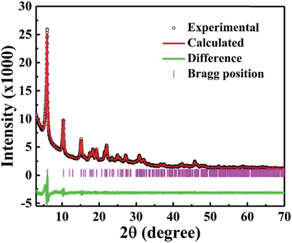
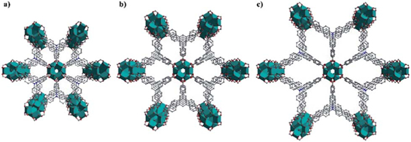
The reaction of titanium isopropoxide with the tritopic carboxylate ligand H3TCA in DMF formed a new porous Ti-MOF ZSTU-1. ZSTU-1 was obtained as regular hexagonal nanorods as confirmed via SEM and TEM (Fig. S1†). The size of the crystallites in our Ti-MOF samples was quite small, making it very difficult to directly determine the crystal structures from single-crystal diffraction measurements. Therefore, we relied on powder X-ray diffraction (PXRD) analysis to elucidate the MOF structures. PXRD patterns were collected for fully activated samples. Based on the data, all three MOF structures were first indexed to the same hexagonal P63/mcm space group, which suggests that they are likely isoreticular. Lattice parameters were then accurately determined from Le Bail refinements. Fig. 1 shows the PXRD data of ZSTU-1 along with the refinement as an example. Based on the metal center compositions derived from elemental analysis (EA) and TGA, and the known ligand structures, preliminary crystal structure models were then successfully constructed. Note that the low resolution of the lab X-ray data precluded the use of Rietveld refinement to further accurately determine the atomic coordinates. Therefore, geometry optimizations based on DFTD calculations were instead performed to enhance the structural models. Detailed lattice parameters and atomic coordinates are provided in Table S1.† ZSTU-1 crystallizes in the hexagonal space group P63/mcm with cell parameters, , , and and satisfactory residual values (,). Six Ti atoms are joined into a six connected subunit, and then the Ti6 clusters are connected via groups to form an infinite SBU along the c-axis. This 1D infinite Ti–O rod is quite similar to the infinite nanowire in MOF MIL-177-HT reported by Serre’s group which can only be obtained from by temperature (280 °C) phase transformation.44 The subunit has a connectivity of six with a hexagonal shape and is extended by the triangular TCA linker, forming a 2D layer structure with a (3,6)-connected kdg network. The 2D layers are connected via groups along the c-axis to form a 3D porous structure, exhibiting elliptical pores with a size of 0.61 × 0.34 nm along the c-axis (Fig. 2a). The structure of ZSTU-1 can be described as parallel aligned Ti–O nanorod arrays connected via organic linkers. The experimental powder XRD pattern for ZSTU-1 matches well with the simulated one, which confirmed the phase purity of the bulk materials (Fig. S2†). Elemental analysis data revealed the chemical formula of ZSTU-1 to be, calcd: C. 41.24%; H, 3.32%; N, 4.00% and found: C, 41.45%; H, 3.64%; N, 3.64%. ZSTU-1 is thermally stable up to 200 C, as shown in Fig. S3.† Above 400 °C, the organic ligand starts to decompose. The residual mass of TiO2 is 36 wt% under air atmosphere, which matches well with the calculated value of 35.3 wt%. ZSTU-1 exhibits excellent stability under water and acid conditions for several days as confirmed via PXRD (Fig. S4a†). When H3TCA was replaced with other tritopic carboxylate ligands such as H3BTB and H3BTCA ligands, two new isoreticular Ti-MOFs were obtained, with the formula of (ZSTU-2) and (ZSTU-3), respectively. In ZSTU-2 and ZSTU-3, the elliptical pores exhibit sizes of 0.85 × 0.46 nm and 1.37 × 0.71 nm along the c-axis, respectively. The phase purity of the bulk ZSTU-2 and ZSTU-3 was also confirmed from the PXRD pattern (Fig. S2†). Also, ZSTU-2 and ZSTU-3 exhibit excellent stability under water and acid conditions (Fig. S4b and c†). The BET surface areas of ZSTU-1, ZSTU-2 and ZSTU-3 are about 536 m2 g−1, 628 m2 g−1 and 861 m−2 g−1, respectively, confirming their porous structures (Fig. S5†).
Fig. 1.
PXRD analysis of ZSTU-1 displaying the experimental pattern (black circles), calculated pattern based on Le Bail refinement (red), the difference plot (green) and Bragg positions (pink).
Fig. 2.
The crystal structures of ZSTU-1 (a), ZSTU-2 (b) and ZSTU-3 (c) that show systematically variable pores.
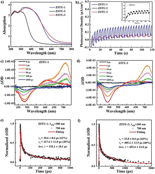
The diffuse reflectance spectra were obtained for the new Ti-MOFs (Fig. 3a). ZSTU-1 and ZSTU-3 showed obvious visible light absorption, which is even extended up to 800 nm, while for ZSTU-2, only slight absorption in the visible light region was observed. The absorption maxima () of ZSTU-1, ZSTU-2 and ZSTU-3 are located at about 350 nm, 305 nm and 320 nm, respectively, which is ascribed to the LMCT process. The photoexcited electron transfer from the ligands to Ti clusters of MOFs results in the reduction of Ti4+ to Ti3+, which could be confirmed via the color change of Ti-MOFs under light illumination and in the electron paramagnetic resonance (EPR) spectrum as shown in Fig. S8.† The detection of paramagnetic Ti3+ confirms the occurrence of LMCT from organic ligands to Ti-oxo clusters. After the LMCT process, the reduced Ti3+ can act as a reaction center for reduction reactions. The bandgap energies of ZSTU-1, ZSTU-2 and ZSTU-3 are calculated to be 2.3 eV, 3.1 eV and 2.2 eV, respectively, from the Tauc plot. Compared with the BTB ligand-based Ti-MOFs, both the TCA and BTCA ligand based Ti-MOFs have smaller band gaps which mainly result from the strong electron-donating ability of triphenylamino groups. ZSTU-3 demonstrates broader light absorption compared with ZSTU-1, which results from the elongated conjugated ligand of BTCA in ZSTU-3. The bandgaps of ZSTU-1 and ZSTU-3 are smaller than those of the most studied Ti MOF MIL-125 (3.6 eV) and its isostructure MIL-125-NH2 (2.6 eV), and MIL-177-HT (3.67 eV) with infinite Ti–O SBUs.16,29 The photoelectrochemical measurement results indicate that ZSTU-1 and ZSTU-3 are highly photoactive under visible light illumination (Fig. 3b), while ZSTU-2 shows low visible light photoactivity. Mott–Schottky measurements were performed to reveal the flat band potential of all three Ti-MOFs, as shown in Fig. S9.† The positive slope indicates the n-type behavior of ZSTU-1, ZSTU-2 and ZSTU-3. The flat band potentials of ZSTU-1, ZSTU-2 and ZSTU-3 are −0.36 V, −0.28 V and −0.31 V (vs. Ag/AgCl), respectively. Based on the results above, apparently all three MOFs, especially ZSTU-1 and ZSTU-3 have demonstrated great potential to act as visible light responsive photocatalysts. Also, the optical properties and photo-response activities can be successfully modulated via ligand substitution. The photocatalytic activity of MOFs not only depends on the bandgap and porosity, but also depends on the lifetime of the photogenerated charge-separated state. To investigate the excited state dynamics, femtosecond transient absorption (TA) spectroscopy was performed using 380 nm excitation of ZSTU- MOFs. As shown in Fig. 3c, the TA spectra of ZSTU-1 showed negative ground state bleach (GSB) absorption from 430 nm to 560 nm with negative signals and excited state absorption (ESA) at with positive signals, while the TA spectra of ZSTU-3 displayed a GSB from 430 nm to 570 nm and ESA at . No ESA signal was found in the visible light region for ZSTU-2, due to its low absorption in this region. The ESA signal refers to the photo-induced absorption process of excited states of samples. The TA kinetics of ZSTU-1 and ZSTU-3 for ESA at 700 nm are shown in Fig. 3e and f. By fitting the kinetics using a biexponential function, the mean relaxation lifetimes of the excited state for ZSTU-1 and ZSTU-3 are found to be 193.1 ± 10.1 ps and 453.6 ± 13.0 ps, respectively. The lifetime of the excited states for ZSTU-3 is obviously much longer than that for ZSTU-1, which will benefit the photocatalytic activity. The results above indicate that the length extension of triphenylamino groups in Ti-MOFs not only increases optical absorption in the visible-light region and BET surface areas but also lengthens the lifetime of the photo-induced electron transfer process, which will be beneficial for efficient photocatalysis.
Fig. 3.
(a) UV-Vis absorption spectra of ZSTU-1, ZSTU-2 and ZSTU-3. (b) Zero-bias photocurrent response of ZSTU-1, ZSTU-2 and ZSTU-3 under chopped visible light illumination. Evolution of femtosecond TA spectra of (c) ZSTU-1 and (d) ZSTU-3 at different delay times (excitation at 380 nm). TA kinetics of (e) ZSTU-1 and (f) ZSTU-3 probed at 700 nm.
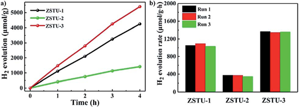
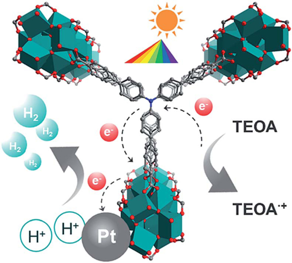
The high porosity, uniform 1D Ti–O rod arrays as active sites and broad absorption in the visible-light region make these Ti-MOFs ideal candidates for photo-catalytic H2 evolution. The photocatalytic activities of the three Ti-MOFs have been examined for H2 evolution under visible light irradiation () by using Pt as the co-catalyst and triethanolamine (TEOA) as the sacrificial agent in a TEOA/CH3CN/H2O system as applied in many MOF systems.45,46 As shown in Fig. 4a, all the three Ti MOFs showed visible-light-driven H2 evolution. The photocatalytic H2 production rates for ZSTU-1, ZSTU-2, and ZSTU-3 are 1060 μmol g−1 h−1, 350 μmol g−1 h−1 and 1350 μmol g−1 h−1, respectively. ZSTU-2 exhibits the lowest photocatalytic activity due to its poor absorption in the visible light region and thus exhibits low photoactivity under visible light illumination. The photocatalytic rate of ZSTU-3 is almost 4 times that of ZSTU-2, making it one of the best MOF photocatalysts (Table S4†). The photocatalytic rate of ZSTU-3 is 2.3 times that of MIL-125-NH2 (588 μmol g−1 h−1) under similar conditions.47 The elongated triphenylamine-based ligand in ZSTU-3 can extend the light absorption and obviously improves charge separation, resulting in enhanced photocatalytic activity. By utilizing rational strategies such as metal doping, post-ligand modulation with functional groups, and incorporation with photoactive organic molecules or inorganic semiconductors, the photocatalytic activities of these Ti-MOFs are expected to be further improved. Another vital standard to evaluate the photocatalyst is the stability. Fig. 4b shows the H2 production amount of ZSTU- for three runs, and indicates that all the three Ti-MOFs are robust after three runs under visible light irradiation. The possible mechanism for the photocatalytic H2 evolution process of ZSTU- MOFs is shown in Fig. 5. Under visible-light illumination, organic ligands absorb light and transfer electrons to the infinite Ti–O rod through the LMCT mechanism, reducing Ti4+ to Ti3+ and generating holes in the organic linker. Then, the Pt co-catalysts separate the photo-generated electrons and reduce H+ to generate H2 and the holes in the linker react with the electron donor TEOA.
Fig. 4.
(a) The amount of H2 produced using ZSTU-1, ZSTU-2 and ZSTU-3 as a function of time under visible light illumination (). (b) Recycling performance of ZSTU-1, ZSTU-2 and ZSTU-3 for photocatalytic H2 evolution for three runs under visible light illumination.
Fig. 5.
Schematic illustration of the H2 evolution mechanism of Ti-MOFs.
Conclusions
In conclusion, we developed a new approach for the synthesis of infinite Ti–O rod-based MOFs. Three new porous Ti-MOFs ZSTU-1, ZSTU-2, ZSTU-3 with tunable porosities and optoelectronic properties were successfully designed and fabricated. All the three MOFs, especially ZSTU-3, have exhibited superior photocatalytic performances and stability for visible light photocatalytic H2 evolution, due to the extended light absorption, larger surface areas and more efficient charge separation. This work might open up new insights into the fabrication of highly effective visible-light photocatalysts for H2 evolution in the future.
Supplementary Material
Acknowledgements
This work was supported by the National Natural Science Foundation of China (51602301 and 51672251), Welch Foundation (AX-1730) and Science Foundation of Zhejiang Sci-Tech University (ZSTU) under Grant No. 13012138-Y. X. F. L. acknowledges the support from the Ministry of Science and Technology (2016YFA0200700 and 2017YFA0205004) and National Natural Science Foundation of China (21673054 and 11874130).
Footnotes
Conflicts of interest
There are no conflicts to declare.
Electronic supplementary information (ESI) available: The Experimental section, XRD patterns, BET analysis and XPS spectra of the samples. See DOI: 10.1039/c9ta01942a
Notes and references
- 1.Ager JW and Lapkin AA, Science, 2018, 360, 707–708. [DOI] [PubMed] [Google Scholar]
- 2.Kabir E, Kumar P, Kumar S, Adelodun AA and Kim K-H, Renewable Sustainable Energy Rev., 2018, 82, 894–900. [Google Scholar]
- 3.Tee SY, Win KY, Teo WS, Koh LD, Liu S, Teng CP and Han MY, Adv. Sci, 2017, 4, 1600337. [DOI] [PMC free article] [PubMed] [Google Scholar]
- 4.Wang Q, Hisatomi T, Jia Q, Tokudome H, Zhong M, Wang C, Pan Z, Takata T, Nakabayashi M. and Shibata N, Nat. Mater, 2016, 15, 611–615. [DOI] [PubMed] [Google Scholar]
- 5.Schultz DM and Yoon TP, Science, 2014, 343, 1239176. [DOI] [PMC free article] [PubMed] [Google Scholar]
- 6.Huang Y-B, Liang J, Wang X-S and Cao R, Chem. Soc. Rev, 2017, 46, 126–157. [DOI] [PubMed] [Google Scholar]
- 7.Zhu L, Liu X-Q, Jiang H-L and Sun L-B, Chem. Rev, 2017, 117, 8129–8176. [DOI] [PubMed] [Google Scholar]
- 8.Furukawa H, Cordova KE, O’Keeffe M. and Yaghi OM, Science, 2013, 341, 1230444. [DOI] [PubMed] [Google Scholar]
- 9.Liang Z, Qu C, Guo W, Zou R. and Xu Q, Adv. Mater, 2018, 30, 1702891. [DOI] [PubMed] [Google Scholar]
- 10.Dhakshinamoorthy A, Li Z. and Garcia H, Chem. Soc. Rev, 2018, 47, 8134–8172. [DOI] [PubMed] [Google Scholar]
- 11.Wang W, Xu X, Zhou W. and Shao Z, Adv. Sci, 2017, 4, 1600371. [DOI] [PMC free article] [PubMed] [Google Scholar]
- 12.Hendon CH, Rieth AJ, Korzyński MD and Dinć ă M, ACS Cent. Sci, 2017, 3, 554–563. [DOI] [PMC free article] [PubMed] [Google Scholar]
- 13.Dhakshinamoorthy A, Asiri AM and García H, Angew. Chem., Int. Ed, 2016, 55, 5414–5445. [DOI] [PubMed] [Google Scholar]
- 14.Meyer K, Ranocchiari M. and van Bokhoven J, Energy Environ. Sci, 2015, 8, 1923–1937. [Google Scholar]
- 15.Wang Y, Huang N-Y, Shen J-Q, Liao P-Q, Chen X-M and Zhang J-P, J. Am. Chem. Soc, 2017, 140, 38–41. [DOI] [PubMed] [Google Scholar]
- 16.Fu Y, Sun D, Chen Y, Huang R, Ding Z, Fu X. and Li Z, Angew. Chem., Int. Ed, 2012, 51, 3364–3367. [DOI] [PubMed] [Google Scholar]
- 17.Li F, Wang D, Xing Q-J, Zhou G, Liu S-S, Li Y, Zheng L-L, Ye P. and Zou J-P, Appl. Catal., B, 2019, 243, 621–628. [Google Scholar]
- 18.Zhou G, Wu M-F, Xing Q-J, Li F, Liu H, Luo X-B, Zou J-P, Luo J-M and Zhang A-Q, Appl. Catal., B, 2018, 220, 607–614. [Google Scholar]
- 19.Kataoka Y, Sato K, Miyazaki Y, Masuda K, Tanaka H, Naito S. and Mori W, Energy Environ. Sci, 2009, 2, 397–400. [Google Scholar]
- 20.Xiao JD, Han LL, Luo J, Yu SH and Jiang HL, Angew. Chem., Int. Ed, 2018, 57, 1103–1107. [DOI] [PubMed] [Google Scholar]
- 21.Lan G, Zhu Y-Y, Veroneau SS, Xu Z, Micheroni D. and Lin W, J. Am. Chem. Soc, 2018, 140, 5326–5329. [DOI] [PubMed] [Google Scholar]
- 22.Shi D, Zheng R, Sun MJ, Cao X, Sun CX, Cui CJ, Liu CS, Zhao J. and Du M, Angew. Chem., Int. Ed, 2017, 56, 14637–14641. [DOI] [PubMed] [Google Scholar]
- 23.Wu ZL, Wang CH, Zhao B, Dong J, Lu F, Wang WH, Wang WC, Wu GJ, Cui JZ and Cheng P, Angew. Chem., Int. Ed, 2016, 55, 4938–4942. [DOI] [PubMed] [Google Scholar]
- 24.Horiuchi Y, Toyao T, Saito M, Mochizuki K, Iwata M, Higashimura H, Anpo M. and Matsuoka M, J. Phys. Chem. C, 2012, 116, 20848–20853. [Google Scholar]
- 25.Zhang FM, Sheng JL, Yang ZD, Sun XJ, Tang HL, Lu M, Dong H, Shen FC, Liu J. and Lan YQ, Angew. Chem., Int. Ed, 2018, 57, 12106–12110. [DOI] [PubMed] [Google Scholar]
- 26.Chen B, Eddaoudi M, Hyde S, O’Keeffe M. and Yaghi O, Science, 2001, 291, 1021–1023. [DOI] [PubMed] [Google Scholar]
- 27.Yuan S, Qin JS, Xu HQ, Su J, Rossi D, Chen YP, Zhang LL, Lollar C, Wang Q, Jiang HL, Son DH, Xu HY, Huang ZH, Zou XD and Zhou HC, ACS Cent. Sci, 2018, 4, 105–111. [DOI] [PMC free article] [PubMed] [Google Scholar]
- 28.Walsh A, Butler KT and Hendon CH, MRS Bull., 2016, 41, 870–876. [Google Scholar]
- 29.Hendon CH, Tiana D, Fontecave M, Sanchez C. m., D’arras L, Sassoye C, Rozes L, Mellot-Draznieks C. and Walsh A, J. Am. Chem. Soc, 2013, 135, 10942–10945. [DOI] [PubMed] [Google Scholar]
- 30.Ke W, Priyanka P, Vegiraju S, Stoumpos CC, Spanopoulos I, Soe CMM, Marks TJ, Chen M-C and Kanatzidis MG, J. Am. Chem. Soc, 2017, 140, 388–393. [DOI] [PubMed] [Google Scholar]
- 31.Chiykowski VA, Cao Y, Tan H, Tabor DP, Sargent EH, Aspuru-Guzik A. and Berlinguette C, Angew. Chem., Int. Ed, 2018, 57, 15529–15533. [DOI] [PubMed] [Google Scholar]
- 32.Xia Z, He C, Wang X. and Duan C, Nat.Commun, 2017, 8, 361. [DOI] [PMC free article] [PubMed] [Google Scholar]
- 33.Wu P, He C, Wang J, Peng X, Li X, An Y. and Duan C, J. Am. Chem. Soc, 2012, 134, 14991–14999. [DOI] [PubMed] [Google Scholar]
- 34.Wu X-P, Gagliardi L. and Truhlar DG, J. Am. Chem. Soc, 2018, 140, 7904–7912. [DOI] [PubMed] [Google Scholar]
- 35.Logan MW, Ayad S, Adamson JD, Dilbeck T, Kenneth HB and Uribe-Romo FJ, J. Mater. Chem. A, 2017, 5, 11854–11863. [Google Scholar]
- 36.Assi H, Mouchaham G, Steunou N, Devic T. and Serre C, Chem. Soc. Rev, 2017, 46, 3431–3452. [DOI] [PubMed] [Google Scholar]
- 37.Nguyen HL, Gándara F, Furukawa H, Doan TL, Cordova KE and Yaghi OM, J. Am. Chem. Soc, 2016, 138, 4330–4333. [DOI] [PubMed] [Google Scholar]
- 38.Yuan S, Liu T-F, Feng D, Tian J, Wang K, Qin J, Zhang Q, Chen Y-P, Bosch M. and Zou L, Chem. Sci, 2015, 6, 3926–3930. [DOI] [PMC free article] [PubMed] [Google Scholar]
- 39.Bueken B, Vermoortele F, Vanpoucke DEP, Reinsch H, Tsou CC, Valvekens P, De Baerdemaeker T, Ameloot R, Kirschhock CEA, Van Speybroeck V, Mayer JM and De Vos D, Angew. Chem., Int. Ed, 2015, 54, 13912–13917. [DOI] [PubMed] [Google Scholar]
- 40.Gao J, Miao J, Li P, Teng W, Yang L, Zhao Y, Liu B. and Zhang Q, Chem. Commun, 2014, 50, 3786–3788. [DOI] [PubMed] [Google Scholar]
- 41.Dan-Hardi M, Serre C, Frot T, Rozes L, Maurin G, Sanchez C. and Férey G, J. Am. Chem. Soc, 2009, 131, 10857–10859. [DOI] [PubMed] [Google Scholar]
- 42.Balajka J, Hines MA, DeBenedetti WJ, Komora M, Pavelec J, Schmid M. and Diebold U, Science, 2018, 361, 786–789. [DOI] [PubMed] [Google Scholar]
- 43.Tachikawa T, Tojo S, Fujitsuka M, Sekino T. and Majima T, J. Phys. Chem. B, 2006, 110, 14055–14059. [DOI] [PubMed] [Google Scholar]
- 44.Wang S, Kitao T, Guillou N, Wahiduzzaman M, Martineau-Corcos C, Nouar F, Tissot A, Binet L, Ramsahye N, Devautour-Vinot S, Kitagawa S, Seki S, Tsutsui Y, Briois V, Steunou N, Maurin G, Uemura T. and Serre C, Nat. Commun, 2018, 9, 1660. [DOI] [PMC free article] [PubMed] [Google Scholar]
- 45.Fang XZ, Shang QC, Wang Y, Jiao L, Yao T, Li YF, Zhang Q, Luo Y. and Jiang HL, Adv. Mater, 2018, 30, 1705112. [DOI] [PubMed] [Google Scholar]
- 46.Xiao JD, Shang QC, Xiong YJ, Zhang Q, Luo Y, Yu SH and Jiang HL, Angew. Chem., Int. Ed, 2016, 55, 9389–9393. [DOI] [PubMed] [Google Scholar]
- 47.Sun D, Liu W, Fu Y, Fang Z, Sun F, Fu X, Zhang Y. and Li Z, Chem.–Eur. J, 2014, 20, 4780–4788. [DOI] [PubMed] [Google Scholar]
Associated Data
This section collects any data citations, data availability statements, or supplementary materials included in this article.


