Abstract
The rapid development of 3D printing (or additive manufacturing) technologies demands new materials with novel properties and functionalities. Superhydrophobic materials, owing to their ultralow water adhesion, self‐cleaning, anti‐biofouling, or superoleophilic properties are useful for myriad applications involving liquids. However, the majority of the methods for making superhydrophobic surfaces have been based on surface functionalization and coatings, which are challenging to apply to 3D objects. Additionally, these coatings are vulnerable to abrasion due to low mechanical stability and limited thickness. Here, a new materials concept and methodology for 3D printing of superhydrophobic macroscopic objects with bulk nanostructure and almost unlimited geometrical freedom is presented. The method is based on a specific ink composed of hydrophobic (meth)acrylate monomers and porogen solvents, which undergoes phase separation upon photopolymerization to generate inherently nanoporous and superhydrophobic structures. Using a desktop Digital Light Processing printer, superhydrophobic 3D objects with complex shapes are demonstrated, with ultralow and uniform water adhesion measured with scanning droplet adhesion microscopy. It is shown that the 3D‐printed objects, owing to their nanoporous structure throughout the entire volume, preserve their superhydrophobicity upon wear damage. Finally, a superhydrophobic 3D‐printed gas‐permeable and water‐repellent microfluidic device and a hierarchically structured 3D‐printed super‐oil‐absorbent are demonstrated.
Keywords: 3D printing, phase separation, superhydrophobicity
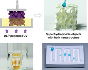
The principle of polymerization‐induced phase separation is exploited to 3D print superhydrophobic objects with bulk nanostructure and unlimited geometrical freedom. The bulk nanoporous structure of the 3D‐printed superhydrophobic objects not only makes them tolerant to abrasion damage, but also opens new possibilities in applications including gas‐permeable and water‐repellent microfluidics, as well as hierarchically structured super oil absorbents.
1. Introduction
3D printing is a disruptive technology that rapidly translates virtual 3D models into tangible objects via digital assembly. Compared with traditional manufacturing, 3D printing offers several significant advantages, including less waste production, ease of customization, and enormous design flexibility.[ 1 ] Encouragingly, the rapid development in 3D‐printing techniques has substantially improved its precision, speed and building volume,[ 2 , 3 , 4 , 5 ] moving 3D printing from a once‐niche technology for rapid prototyping to industrial‐scale manufacturing of commodities and constructions.[ 6 ] However, the choice of printable materials is still limited, which restricts the functionality and application of fabricated objects. To realize the full potential of 3D printing, it is crucial to develop novel inks that can lead to 3D objects with qualitatively new properties and functionalities.
Surface wettability is an important physicochemical property of materials that dictates their interactions with liquids.[ 7 ] Superhydrophobicity, originally inspired by the purity of the lotus leaf,[ 8 ] has attracted attention from both fundamental and application perspectives.[ 9 , 10 , 11 ] Superhydrophobicity is typically characterized by a high apparent water contact angle (θ* > 150°) and a low sliding angle (α) or contact angle hysteresis (CAH). Such extreme water repellency endows superhydrophobic materials with many intriguing properties, including self‐cleaning,[ 12 ] low friction,[ 13 ] anti‐corrosion,[ 14 ] anti‐icing,[ 15 ] and anti‐biofouling.[ 15 ] Therefore, the ability to print superhydrophobic objects can extend the applications of 3D printing to broad fields from liquid transportation, heat transfer, energy harvesting to biomedical engineering.
The realization of superhydrophobicity requires the synergetic effect of high surface roughness and low surface energy to ensure that water droplets stay in a Cassie–Baxter state.[ 16 ] In this state, the liquid–solid contact fraction (f s) is small, leading to a high water contact angle and a low droplet adhesion force. Recently, a few studies have exploited 3D printing to create superhydrophobic materials by direct “printing” of the nanostructures or microstructures to achieve a high surface roughness.[ 17 , 18 , 19 , 20 , 21 , 22 ] However, printing of nanostructures is time‐consuming because of the inherent competition between printing speed and time; therefore, it can only be used to create superhydrophobic 2D films rather than 3D objects.[ 17 , 18 , 19 ] While superhydrophobic 3D objects have been fabricated by printing microstructures on their interface, this strategy is challenging to apply for complex and intricate geometries and is limited to simple‐shaped objects, such as cubes or cylinders.[ 22 ]
Another approach to endow 3D objects with superhydrophobicity is post‐modification (e.g., spray coating or dip coating with nanoparticles).[ 23 ] However, such methods lead to 3D structures with a thin superhydrophobic layer, which has several limitations. First, coating methods cannot be easily applied to the shaded or internal surfaces of complex 3D objects. Second, the thin coating layer is susceptible to mechanical abrasion, which damages the surface topography and leads to the loss of superhydrophobicity.[ 16 ]
An effective strategy to achieve mechanically robust superhydrophobicity is by micro/nano structuring throughout the whole bulk material.[ 24 , 25 , 26 , 27 ] When the top layer of the material is abraded, a fresh surface with a similar micro/nanoscale topography gets exposed and preserves the superhydrophobicity. Such a characteristic makes bulk superhydrophobic materials much more durable than thin superhydrophobic coatings. Nevertheless, these materials have only been fabricated by casting or molding method, with limited geometrical complexity.[ 24 , 25 , 26 , 27 ]
To address these challenges, we present a new materials concept to 3D print superhydrophobic objects with bulk nanostructure and unlimited geometrical freedom. Our methodology is based on a newly developed 3D‐printing system that combines Digital Light Processing (DLP) 3D printing with polymerization‐induced phase separation to form nanoporous 3D structures.[ 28 , 29 ] Herein, we leverage such inherent nanoporosity to create bulk superhydrophobic 3D objects without any post‐modification. We systematically investigate the structure–property relationship of the 3D‐printed objects by adjusting their porous structure and surface chemistry. The wetting property of the 3D superhydrophobic objects, which is difficult to characterize by the conventional contact angle method, is measured using scanning droplet adhesion microscopy (SDAM).[ 30 ] Further we show that due to self‐similar porous structures throughout the entire volume of the fabricated 3D objects, they remain nonwettable even upon abrasion damage. Finally, we demonstrate a 3D‐printed superhydrophobic microfluidic device which is gas permeable but liquid impermeable, and a 3D‐printed hierarchical macro‐nano porous structure as a super oil absorbent.
2. Results and Discussion
DLP printing is a layer‐based 3D‐printing technology that uses projected light patterns to cure an entire layer instantly, thus enabling faster printing speed and larger building volume.[ 1 ] Most inks used for DLP printing are made of monomers and/or crosslinkers leading to nonporous 3D objects. In this study, we design a novel ink composed of hydrophobic (meth)acrylate monomers and porogen solvents, which undergo phase separation during the photopolymerization process, forming a bi‐continuous 3D structure consisting of a polymer‐rich phase and a polymer‐poor phase.[ 28 ] Subsequent leaching of the polymer‐poor phase followed by supercritical drying generates superhydrophobic 3D objects with bulk nanoporous structure. (Figure 1a,b).
Figure 1.
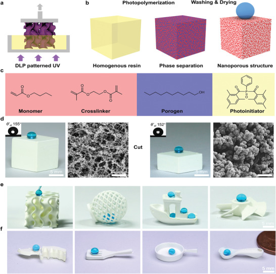
3D printing of superhydrophobic objects with bulk nanostructure. a) Schematic showing the DLP 3D‐printing process using a phase‐separating ink. b) In this process, photopolymerization induces phase separation of the homogenous ink and generates the inherent nanoporous structures leading to bulk superhydrophobicity. c) Chemical structures of the components of an exemplary ink: BA as the monomer (30 wt%), EDMA as the crosslinker (20 wt%), 1‐decanol as the porogen (50 wt%), and Irgacure 819 as the photoinitiator (2 wt% relative to reactive monomers). d) Photographs of dyed water droplets on the surface (left panel) and cross‐section (right) of a cube printed using the phase separating ink, with the insert showing the measured static water contact angle (θ* st). The nanoporous structure of the cube is shown in the corresponding scanning electron microscopy (SEM) images. e) Complex‐shaped superhydrophobic objects printed using the novel ink demonstrating the design flexibility. f) A superhydrophobic miniaturized kitchen set (knife, spatula, pan and spoon) printed using the ink.
To illustrate the principle of our method, we first selected an ink consisting of a hydrophobic butyl acrylate (BA, 30 wt%), ethylene glycol dimethacrylate (EDMA, 20 wt%), 1‐decanol (50 wt%) and Irgacure 819 as the monomer, crosslinker, porogen and photoinitiator, respectively (Figure 1c). 1‐Decanol was selected as the porogen because of its good miscibility with the monomer and low viscosity and nonvolatility required for DLP 3D printing. As an example, we printed a cube (10 × 10 × 10 mm3) using the ink. Figure 1d shows sub‐micrometer porosity for the external and internal surfaces of the 3D‐printed cube, which is a result of the polymerization‐induced phase separation. The 3D‐printed cube is superhydrophobic in bulk, as demonstrated by its high static water contact angle (θ* st) and low sliding angle (α) both on the surface (θ* st, 155° and α, 5°, respectively) and on the cross‐section (θ* st, 152° and α, 8°, respectively). In contrast, a cube printed using an ink containing the same monomers but without porogens is nonporous, and therefore possesses only moderate hydrophobicity with θ* st of 74° (Figure S1, Supporting Information). This clearly demonstrates the critical role of porosity to achieve superhydrophobicity: the nanostructure suspends the liquid in a Cassie state with a low solid–liquid fraction (f s), leading to high apparent contact angles and low adhesion (Discussion S1, Supporting Information). Notably, the supercritical drying step is crucial for preserving the surface porosity of the 3D‐printed nanoporous objects. Drying a printed object in air leads to a collapse of surface porosity due to capillary forces, giving rise to a much less porous and non‐superhydrophobic surface (Figure S2, Supporting Information).
To demonstrate the design flexibility of our method and the advantages of 3D printing, we printed a broad range of various 3D shapes (Figure 1e,f) from complex‐shaped structures (gyroid, spherical lattice, boat, propeller) that are challenging to achieve by extrusion‐based methods (Figure 1e) to simpler structures (miniaturized superhydrophobic kitchen set: knife, spatula, pan and spoon, Figure 1f). Water droplets bead up on the surface and also move freely inside the 3D‐printed hollow structures (Figure 1e; Video S1, Supporting Information), demonstrating their superhydrophobicity. We further probed the printing resolution of the method for the developed hydrophobic inks by printing a series of pillars with different diameters (from 50 µm to 500 µm) and fixed heights (1 mm). Results show that pillars having diameters larger than 150 µm can be printed within a deviation of the DLP pixel size (50 µm), indicating a printing feature size of ≈200 µm (Figure S4, Supporting Information).
The surface wettability of a material is dictated by both surface chemistry and topography. Therefore, we systematically studied the influence of the porous structure and chemical composition of 3D‐printed objects on their wettability (superhydrophobicity) using inks covering a wide range of monomer and porogen combinations (Tables S1–S3, Supporting Information). We also studied the mechanical strength of the superhydrophobic objects, which is crucial for their practical applications. Three hydrophobic monomers (butyl acrylate (BA), lauryl acrylate (LA) and hexafluorobutyl acrylate/butyl acrylate mixture (HFBA‐BA)) were used to demonstrate the universality of the method. Cyclohexanol (good solvent) and 1‐decanol (bad solvent) were used as the porogen solvents. First, we varied the mass ratio of good to bad solvent from 0:1, 1:1 to 1:0, while keeping the porogen fraction in the ink constant (50 wt%). As shown in Figure 2a and Tables S1–S3 in the Supporting Information, increasing the good to bad solvent ratio barely influences the porosity of the structures, but significantly decreases the polymer globular size: from 637 to 57 nm for BA, 740 to 51 nm for LA, and 993 to 87 nm for HFBA‐BA. This leads to an increase in their CAH (i.e., the difference between θ* adv and θ* rec), from 13.1° to 58.2° for BA, 13.6° to 42.7° for LA, and 9.5° to 11.8° for HFBA‐BA. Among all three monomers, HFBA‐BA gives the best superhydrophobicity (i.e., lowest CAH) for porous objects with the same level of porosity and globular size (Figure 2a,b). This is attributed to the higher hydrophobicity of the HFBA‐BA monomer, as illustrated by the higher water contact angles of its nonporous counterpart (Table S4, Supporting Information), enabling better liquid repellence (i.e., higher apparent contact angles θ* ) for the same liquid–solid fraction (Discussion S1, Supporting Information). On the other hand, the mechanical stability (i.e., compression strength) of the 3D objects shows a significant improvement with an increased good to bad solvent ratio: from 7.6 to 20.1 MPa for BA, from 2.1 to 9.8 MPa for LA, and from 2.5 to 14.9 MPa for HFBA‐BA (Figure 2c). This is consistent with previous studies showing that the compressive strength of brittle porous structures increases with a decrease in the grain (globular) size.[ 31 ] Second, we varied the mass fraction of the porogen in the ink at a fixed porogen composition (cyclohexanol:1‐decanol 1:1). As illustrated in Figure 2d, reducing the porogen fraction from 65 to 35 wt% decreases both the polymer globular size and porosity. This leads to an increase of the solid–liquid contact fraction (f s), and, therefore, a decrease in liquid repellency (i.e., decrease of θ*) (Figure 2e; Discussion S1, Supporting Information). In contrast, the mechanical strength is significantly enhanced due to decreased porosity (Figure 2f; Tables S1–S3, Supporting Information). These results suggest a trade‐off between the superhydrophobicity and mechanical strength of the 3D‐printed nanoporous objects. Among the ink compositions that can lead to superhydrophobicity (CAH < 15°), HFBA‐BA‐3 provides the best mechanical strength (14.9 MPa). As shown in Video S2 in the Supporting Information, a 10 × 10 × 10 mm3 cube printed using the HFBA‐BA‐3 ink can withstand a mass of 1 kg and remain intact and superhydrophobic.
Figure 2.
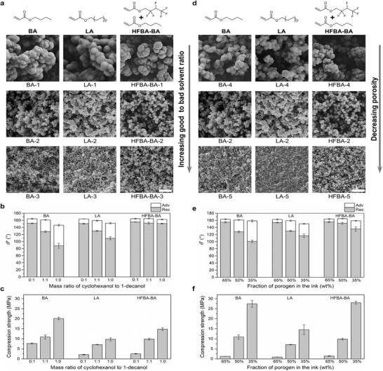
Structure–property relationship of the bulk superhydrophobic objects printed with different ink compositions. a) Cross‐sectional SEM images of 3D‐printed cubes (5 × 5 × 5 mm3) using inks with different porogen composition (i.e., varied cyclohexanol:1‐decanol mass ratio 0:1 (top), 1:1 (middle), 1:1 (bottom)) at a fixed porogen mass fraction (50 wt%). b,c) Apparent advancing (θ* adv) and receding (θ* rec) water contact angles (b) and compression strengths (c) of the corresponding cubes. d) Cross‐sectional SEM images of 3D‐printed cubes (5 × 5 × 5 mm3) using inks with different porogen mass fraction (65% (top), 50% (middle), 35% (bottom) wt%) at a fixed porogen composition (1:1 cyclohexanol:1‐decanol). e,f) Apparent advancing (θ* adv) and receding (θ* rec) water contact angles (e) and compression strengths (f) of the corresponding cubes.
While traditional coating methods are widely used to make open and typically flat surface superhydrophobic, they are not readily applicable to 3D objects with shaded or highly curved surfaces. Our method circumvents this geometric constraint by creating 3D objects that are intrinsically superhydrophobic owing to their inherent nanoporosity. To demonstrate this, we printed a superhydrophobic bowl using the ink HFBA‐BA‐3. As shown in Figure 3a,b; Video S3 in the Supporting Information, both the external and internal surfaces of the 3D‐printed bowl demonstrate excellent water repellency. It is worth noting that the wetting characterization of such curved 3D objects is challenging or impossible using conventional contact angle methods. Therefore, SDAM was used to quantify their wetting properties and variations (Figure 3c). In SDAM, a vertically mounted force sensor is used to record the interaction force between a liquid probe and a sample surface point‐by‐point, with a force sensitivity of ≈9 nN and a spatial resolution of 200 µm.[ 30 ] We first performed single‐point measurements at the inner center position of the 3D‐printed bowls, and a representative force curve is shown in Figure 3d. The samples show very small snap‐in forces that are lost in the sensor noise (≈9 nN) and an average pull‐off force of 3.0 ± 0.8 µN based on five independent samples (Figure 3e). This pull‐off force corresponds to a receding contact angle between 152° and 156°,[ 30 ] consistent with our contact angle measurements (Table S3, Supporting Information). In addition, 2D mapping was conducted on the internal center area (1 × 1 mm2) of a 3D‐printed bowl. The results demonstrate good homogeneity of superhydrophobicity on the curved 3D‐printed surface with pull‐off forces ranging from 0.9 to 6.8 µN (Figure 3f).
Figure 3.
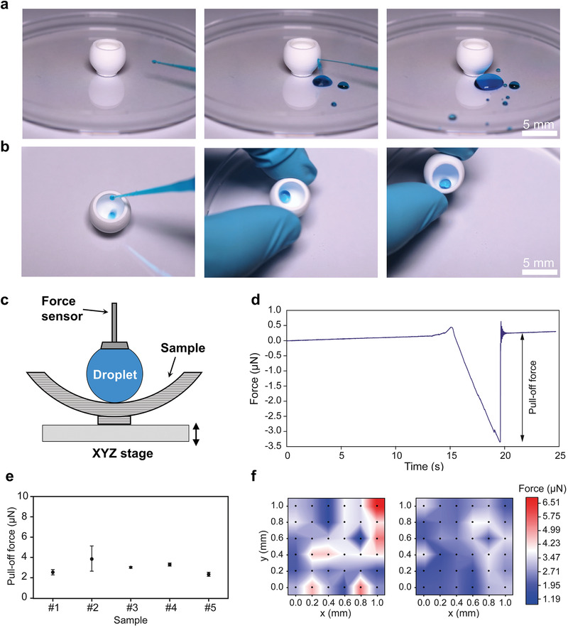
Wetting characterization of 3D‐printed bulk superhydrophobic objects using SDAM. a,b) Snapshots of a video (Video S3, Supporting Information) showing water droplets bouncing and rolling on the external and internal surfaces of a 3D‐printed superhydrophobic bowl. c) Schematic showing the SDAM setup (cross‐section view). d) Typical force curve obtained on the internal center position of a 3D‐printed superhydrophobic bowl. e) Pull‐off force at the inner center position of five independent samples. Error bars are standard deviations based on five repetitive measurements. f) Pull‐off force maps showing the water adhesion on the internal center area (1 × 1 mm2) of two independent samples.
To date, most superhydrophobic materials have been fabricated by post‐modification, i.e., coating a bulk object with a thin superhydrophobic layer. Such coating layers can be easily damaged by abrasion due to roughness, weak adhesion and limited thickness, leading to loss of superhydrophobicity.[ 16 ] The increased mechanical stability of superhydrophobic coatings can be achieved by a smart combination of nanostructures for low water repellency with an armored microstructure to resist abrasion;[ 32 ] however, this method is difficult to apply to curved and/or internal surfaces. An advantage of our method is that the produced superhydrophobic 3D objects are abrasion‐tolerant owing to the bulk nanostructure. The abrasion of the top layer exposes the surface underneath, which is structurally identical to the surface, possessing high porosity and roughness required for superhydrophobicity (Figure 4a,b). To demonstrate this, we fabricated two superhydrophobic structures: a) superhydrophobic brick with bulk nanostructure printed using a porogen‐containing ink (HFBA‐BA‐3) and b) brick printed using an ink without porogen, and post‐modified by a commercial superhydrophobic spray coating. The two superhydrophobic bricks were then abraded on sandpaper under a pressure of 10 kPa for 10 cm. As shown in Figure 4c,g, the bulk superhydrophobic brick remained superhydrophobic with a water sliding angle (α) lower than 10° even after 40 abrasion cycles. In contrast, the post‐modified superhydrophobic structure gradually lost its superhydrophobicity after 25 abrasion cycles, leading to the water droplet pinning effect (Figure 4d,h). SEM imaging revealed that the bulk superhydrophobic brick remained highly porous even after the 40‐cycle abrasion test (Figure 4e), while the post‐modified superhydrophobic brick lost most of the nanoparticle coating layer after abrasion (Figure 4f). These results demonstrate the three‐dimensional bulk superhydrophobicity of the 3D‐printed nanoporous objects. Such tolerance to abrasion damage and mechanical stability, especially on the internal surfaces of a 3D structure that are not accessible for re‐coating, is crucial for practical applications of superhydrophobicity.
Figure 4.
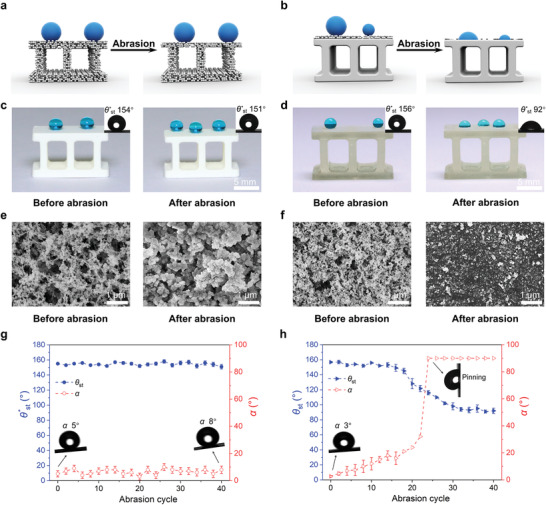
Abrasion test of 3D‐printed superhydrophobic objects with bulk nanostructure versus 3D‐printed objects post‐modified with a superhydrophobic coating. a,b) Schematics showing a bulk superhydrophobic object (a) and a post‐modified superhydrophobic object (b) under abrasion. c,d) Dyed water droplets on a 3D‐printed superhydrophobic brick with bulk nanostructure (c) and a 3D‐printed brick post‐modified with a superhydrophobic coating (d) before and after 40 abrasion cycles. The insets show the measured static water contact angles (θ* st). e,f) SEM images showing the surface morphology of a bulk superhydrophobic brick (e) and a post‐modified superhydrophobic brick (f) before and after 40 abrasion cycles. g,h) Static water contact angle (θ* st) and sliding angle (α) of the bulk superhydrophobic brick (g) and the post‐modified superhydrophobic brick (h) after different abrasion cycles.
A salient feature of the 3D‐printed superhydrophobic objects is their gas permeability, which arises from their porous nature. The ability to transport gases while retaining water is useful for various applications such as microfluidics,[ 33 ] gas–liquid contactors,[ 34 ] blood oxygenation membranes,[ 35 ] and seawater desalination.[ 36 ] As a proof‐of‐concept application, we created a porous superhydrophobic microfluidic device and demonstrated fast transportation of CO2 through the channel walls, while maintaining water flow through the channel itself (Figure 5 ). First, a superhydrophobic channel was printed using the BA‐1 ink (Figure 5b), clearly showing its porous structure (Figure 5c). The channel was then covered and sealed with a transparent superhydrophobic slide (see the Experimental Section for details). Figure 5d; Video S4 in the Supporting Information demonstrate nearly frictionless movement of water droplets inside the superhydrophobic microfluidic channel.
Figure 5.
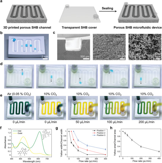
3D‐printed porous superhydrophobic (SHB) microfluidic device. a) Schematic showing the microfluidic fabrication via assembly of a 3D‐printed porous SHB channel and a transparent nonporous SHB cover. b) Photograph showing water droplets forming an almost spherical shape in the 3D‐printed porous SHB channel. c) Cross‐sectional SEM images showing the porosity of the 3D‐printed SHB channel. d) Snapshots of a video (Video S4, Supporting Information) showing a water droplet moving freely in the assembled SHB microfluidic device. e) Snapshots of a video (Video S5, Supporting Information) showing the color change of bromothymol blue solution in the microfluidic device due to CO2 diffusion. The CO2 concentration in the environment is indicated on the top, while the flow rate of the solution is given at the bottom. f) UV–vis spectrum of the bromothymol blue solution at the inlet and outlet of the microfluidic device at a flow rate of 25 µL min−1. g) Ratio of yellow color width to the width of particular loop of the channel at various positions under different flow rates. h) Ratio of acidic yellow area to the channel area (i.e., total area of green and yellow) under different flow rates.
To demonstrate the gas permeability of the microfluidic device, CO2 was selected as a model gas, which can acidify water and can be easily visualized using a pH indicator. The microfluidic device was placed in a closed chamber, and aqueous bromothymol blue (pH indicator) was pumped through (Figure 5e). The color of the solution was green (corresponding to pH ≈ 7) in the air (CO2 concentration of ≈0.05%). When concentration of CO2 in the environment was increased to ≈10% (by introducing dry ice), the solution rapidly changed the color to yellow (corresponding to pH <6) as a result of acidification (Figure 5e,f; Video S5, Supporting Information), indicating fast gas permeation. The acidification can be visualized by following the fraction of the acidic yellow color in the channel (ratio of yellow color width to width of particular loop of the channel, positions 1, 2, and 3 from Figure 5e). By increasing the flow rate, the acidification decreased owing to the decrease of solution residence time, as indicated by the decreased fraction of the acidic yellow color in the channel at each position (Figure 5g). Similarly, with increase of the flow rate from 25 to 400 µL min−1, the fraction of the acidic yellow area in the microfluidic channel gradually decreased from 93% to 20% (Figure 5h), showing the dependence of the CO2 absorption on the solution residence time inside the porous microfluidic channel. PDMS, a widely used material for making microfluidics via soft lithography, is also permeable to some gases‐ [ 37 ] However, gas permeation through PDMS is achieved through a sorption‐diffusion model and is therefore highly dependent on the gas type.[ 38 ] By contrast, the porous nature of our 3D‐printed superhydrophobic objects makes them equally permeable to different gases. Combining this with the design flexibility of 3D printing opens new opportunities for on‐chip multiphase reactions as well as cell culture applications where gas permeability is required.
The nanoporosity of the 3D‐printed objects offers superhydrophobicity, and also leads to superoleophilicity (Figure S5 and Video S7, Supporting Information), making them attractive candidates for selective oil absorption.[ 39 ] To demonstrate such potential, we printed four polymer cubes (9.6 × 9.6 × 9.6 mm3) based on the same monomer (butyl acrylate) but with different structures as shown in Figure 6a: a) nonporous cube (non‐P), b) nanoporous cube (nano‐P), c) macroporous cube made of the nonporous polymer (macro‐P), and d) hierarchically macro–nano porous lattice (macro‐nano‐P). The mass‐based absorption capacities toward different oils (soybean oil, isooctane, and dichloromethane) were measured by immersing the cube in an oil/water mixture and comparing the mass change after contact with the original mass. As shown in Figure 6b, the non‐P cube shows negligible oil absorption for all hydrophobic liquids (<20%). In contrast, the nano‐P cube can take up considerable amounts of oils: 235% for isooctane, 278% for soybean oil, and 338% for dichloromethane. When macropores (0.9 mm in diameter) are introduced by 3D printing, the absorption efficiency of the cubes can be further increased, as shown by the higher absorption efficiency of the macro‐P cube versus non‐P cube, and macro–nano‐P cube versus nano‐P cube. Among all the cubes, the hierarchical macro nano‐P cube shows the highest absorption capacity (473% for isooctane, 566% for soybean oil, and 763% for dichloromethane), owing to its highest overall porosity. In addition, the hierarchical structure can significantly enhance the absorption kinetics of the absorbent, as demonstrated by its rapid absorption toward both heavy and light oils (Figure 6c; Video S8, Supporting Information). These results suggest the potential of the hierarchically porous structures as super absorbents to remove oils and organic solvents from water.
Figure 6.
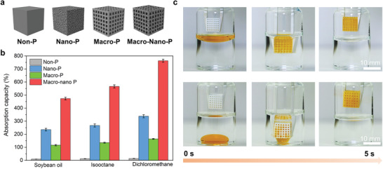
3D‐printed hierarchical porous and superhydrophobic structure for oil absorption. a) Schematic representation of the non‐P, nano‐P, macro‐P, and macro–nano‐P cube. b) Mass‐based oil absorption capacity of the four different types of cubes toward different organic solvents. c) Photographs showing the fast absorption of soybean oil (top) and dichloromethane (bottom) by the hierarchical macro–nano‐P cube.
3. Conclusion
We have developed a new method to 3D print superhydrophobic objects with bulk nanostructure via polymerization‐induced phase separation. The structure–property relationship of the produced superhydrophobic objects was systematically investigated, and the results showed an inherent trade‐off between their water repellency and mechanical strength. SDAM was used to quantify the wetting properties of curved 3D objects which are otherwise difficult to characterize, and revealed their low adhesion force (≈3 µN) and good homogeneity even on their concave surface. Specifically, the superhydrophobicity extends through the entire volume of produced 3D objects, making them more damage‐tolerant than post‐modified superhydrophobic objects. Finally, by taking advantage of the porosity, permeability and, at the same time, superhydrophobicity of 3D‐printed objects, we demonstrated applications of such structures as gas‐permeable but water‐repellent microfluidic devices as well as super oil absorbents.
The design flexibility, mechanical durability and permeability of the 3D bulk superhydrophobic objects makes them applicable in previously not possible applications in various fields, including low‐friction water transportation, underwater gas/involving reactions, cell arrays/aggregations construction, antimicrobial materials, and blood‐repellent medical devices. Additionally, our method allows the fabrication of 3D bulk superhydrophobic objects without using the fluorinated compounds required for most superhydrophobic coatings (e.g., ink BA‐1, LA‐1), thereby reducing cost as well as minimizing environmental impacts. Importantly, the principle of the polymerization‐induced phase separation employed here can be applied to other light‐based 3D‐printing techniques, including two‐photon polymerization and stereolithography. Such versatility opens new possibilities for digital fabrication of both macroscopic and microscopic objects possessing inherent damage‐tolerant superhydrophobicity on all external and internal interfaces, which is useful for a variety of applications where liquid‐surface interactions play a crucial role. On the flip side, our methodology requires a super‐critical drying step that adds production costs, while the material is limited to photopolymerization.
Conflict of Interest
The authors declare no conflict of interest.
Supporting information
Supporting Information
Supplemental Video 1
Supplemental Video 2
Supplemental Video 3
Supplemental Video 4
Supplemental Video 5
Supplemental Video 6
Supplemental Video 7
Supplemental Video 8
Acknowledgements
The Helmholtz Program “Materials Systems Engineering” is thanked. This project was partly supported by DFG (Heisenbergprofessur Projektnummer: 406232485, LE 2936/9‐1), by Business Finland Project TUTL‐SDAM (6798/31/2017), European Research Council grant ERC‐2016‐CoG (725513‐SuperRepel) and Academy of Finland (342169). This work was funded by the Deutsche Forschungsgemeinschaft (DFG, German Research Foundation) under Germany's Excellence Strategy 2082/1‐390761711 (Excellence Cluster "3D Matter Made to Order”).
Open access funding enabled and organized by Projekt DEAL.
Dong Z., Vuckovac M., Cui W., Zhou Q., Ras R. H. A., Levkin P. A., 3D Printing of Superhydrophobic Objects with Bulk Nanostructure. Adv. Mater. 2021, 33, 2106068. 10.1002/adma.202106068
Data Availability Statement
The data that support the findings of this study are available from the corresponding author upon reasonable request.
References
- 1. Ligon S. C., Liska R., Stampfl J., Gurr M., Mülhaupt R., Chem. Rev. 2017, 117, 10212. [DOI] [PMC free article] [PubMed] [Google Scholar]
- 2. Tumbleston J. R., Shirvanyants D., Ermoshkin N., Janusziewicz R., Johnson A. R., Kelly D., Chen K., Pinschmidt R., Rolland J. P., Ermoshkin A., Samulski E. T., DeSimone J. M., Science 2015, 347, 1349. [DOI] [PubMed] [Google Scholar]
- 3. Kelly B. E., Bhattacharya I., Heidari H., Shusteff M., Spadaccini C. M., Taylor H. K., Science 2019, 363, 1075. [DOI] [PubMed] [Google Scholar]
- 4. Walker D. A., Hedrick J. L., Mirkin C. A., Science 2019, 366, 360. [DOI] [PMC free article] [PubMed] [Google Scholar]
- 5. Regehly M., Garmshausen Y., Reuter M., König N. F., Israel E., Kelly D. P., Chou C.‐Y., Koch K., Asfari B., Hecht S., Nature 2020, 588, 620. [DOI] [PubMed] [Google Scholar]
- 6. Zastrow M., Nature 2020, 578, 20. [DOI] [PubMed] [Google Scholar]
- 7. Wang S., Liu K., Yao X., Jiang L., Chem. Rev. 2015, 115, 8230. [DOI] [PubMed] [Google Scholar]
- 8. Barthlott W., Neinhuis C., Planta 1997, 202, 1. [Google Scholar]
- 9. Vakarelski I. U., Patankar N. A., Marston J. O., Chan D. Y. C., Thoroddsen S. T., Nature 2012, 489, 274. [DOI] [PubMed] [Google Scholar]
- 10. Schutzius T. M., Jung S., Maitra T., Graeber G., Köhme M., Poulikakos D., Nature 2015, 527, 82. [DOI] [PubMed] [Google Scholar]
- 11. Tian X., Verho T., Ras R. H. A., Science 2016, 352, 142. [DOI] [PubMed] [Google Scholar]
- 12. Fürstner R., Barthlott W., Neinhuis C., Walzel P., Langmuir 2005, 21, 956. [DOI] [PubMed] [Google Scholar]
- 13. Mertaniemi H., Jokinen V., Sainiemi L., Franssila S., Marmur A., Ikkala O., Ras R. H. A., Adv. Mater. 2011, 23, 2911. [DOI] [PubMed] [Google Scholar]
- 14. Zang D., Zhu R., Zhang W., Yu X., Lin L., Guo X., Liu M., Jiang L., Adv. Funct. Mater. 2017, 27, 1605446. [Google Scholar]
- 15. Wang L., Gong Q., Zhan S., Jiang L., Zheng Y., Adv. Mater. 2016, 28, 7729. [DOI] [PubMed] [Google Scholar]
- 16. Verho T., Bower C., Andrew P., Franssila S., Ikkala O., Ras R. H. A., Adv. Mater. 2011, 23, 673. [DOI] [PubMed] [Google Scholar]
- 17. Dong Z., Schumann M. F., Hokkanen M. J., Chang B., Welle A., Zhou Q., Ras R. H. A., Xu Z., Wegener M., Levkin P. A., Adv. Mater. 2018, 30, 1803890. [DOI] [PubMed] [Google Scholar]
- 18. Lin Y., Zhou R., Xu J., Adv. Mater. Interfaces 2018, 5, 1801126. [Google Scholar]
- 19. Liu X., Gu H., Wang M., Du X., Gao B., Elbaz A., Sun L., Liao J., Xiao P., Gu Z., Adv. Mater. 2018, 30, 1800103. [DOI] [PubMed] [Google Scholar]
- 20. Graeber G., Martin Kieliger O. B., Schutzius T. M., Poulikakos D., ACS Appl. Mater. Interfaces 2018, 10, 43275. [DOI] [PubMed] [Google Scholar]
- 21. Yang Y., Li X., Zheng X., Chen Z., Zhou Q., Chen Y., Adv. Mater. 2018, 30, 1704912. [DOI] [PubMed] [Google Scholar]
- 22. Kaur G., Marmur A., Magdassi S., Addit. Manuf. 2020, 36, 101669. [Google Scholar]
- 23. Lee K.‐M., Park H., Kim J., Chun D.‐M., Appl. Surf. Sci. 2019, 467–468, 979. [Google Scholar]
- 24. Shirtcliffe N. J., McHale G., Newton M. I., Perry C. C., Langmuir 2003, 19, 5626. [Google Scholar]
- 25. Zhu X., Zhang Z., Ren G., Yang J., Wang K., Xu X., Men X., Zhou X., J. Mater. Chem. 2012, 22, 20146. [Google Scholar]
- 26. Jin H., Tian X., Ikkala O., Ras R. H. A., ACS Appl. Mater. Interfaces 2013, 5, 485. [DOI] [PubMed] [Google Scholar]
- 27. Rather A. M., Manna U., Chem. Mater. 2016, 28, 8689. [Google Scholar]
- 28. Dong Z., Cui H., Zhang H., Wang F., Zhan X., Mayer F., Nestler B., Wegener M., Levkin P. A., Nat. Commun. 2021, 12, 247. [DOI] [PMC free article] [PubMed] [Google Scholar]
- 29. Mayer F., Ryklin D., Wacker I., Curticean R., Čalkovský M., Niemeyer A., Dong Z., Levkin P. A., Gerthsen D., Schröder R. R., Wegener M., Adv. Mater. 2020, 32, 2002044. [DOI] [PubMed] [Google Scholar]
- 30. Liimatainen V., Vuckovac M., Jokinen V., Sariola V., Hokkanen M. J., Zhou Q., Ras R. H. A., Nat. Commun. 2017, 8, 1798. [DOI] [PMC free article] [PubMed] [Google Scholar]
- 31. Knudsen F. P., J. Am. Ceram. Soc. 1959, 42, 376. [Google Scholar]
- 32. Wang D., Sun Q., Hokkanen M. J., Zhang C., Lin F.‐Y., Liu Q., Zhu S.‐P., Zhou T., Chang Q., He B., Zhou Q., Chen L., Wang Z., Ras R. H. A., Deng X., Nature 2020, 582, 55. [DOI] [PubMed] [Google Scholar]
- 33. de Jong J., Lammertink R. G. H., Wessling M., Lab Chip 2006, 6, 1125. [DOI] [PubMed] [Google Scholar]
- 34. Geyer F., Schönecker C., Butt H.‐J., Vollmer D., Adv. Mater. 2017, 29, 1603524. [DOI] [PubMed] [Google Scholar]
- 35. Paven M., Papadopoulos P., Schöttler S., Deng X., Mailänder V., Vollmer D., Butt H.‐J., Nat. Commun. 2013, 4, 2512. [DOI] [PMC free article] [PubMed] [Google Scholar]
- 36. Dong Z.‐Q., Wang B.‐J., Ma X.‐h., Wei Y.‐M., Xu Z.‐L., ACS Appl. Mater. Interfaces 2015, 7, 22652. [DOI] [PubMed] [Google Scholar]
- 37. Malankowska M., Martins C. F., Rho H. S., Neves L. A., Tiggelaar R. M., Crespo J. G., Pina M. P., Mallada R., Gardeniers H., Coelhoso I. M., J. Membr. Sci. 2018, 545, 107. [Google Scholar]
- 38. Merkel T. C., Bondar V. I., Nagai K., Freeman B. D., Pinnau I., J. Polym. Sci., Part B: Polym. Phys. 2000, 38, 415. [Google Scholar]
- 39. Chu Z., Feng Y., Seeger S., Angew. Chem., Int. Ed. 2015, 54, 2328. [DOI] [PubMed] [Google Scholar]
Associated Data
This section collects any data citations, data availability statements, or supplementary materials included in this article.
Supplementary Materials
Supporting Information
Supplemental Video 1
Supplemental Video 2
Supplemental Video 3
Supplemental Video 4
Supplemental Video 5
Supplemental Video 6
Supplemental Video 7
Supplemental Video 8
Data Availability Statement
The data that support the findings of this study are available from the corresponding author upon reasonable request.


