Abstract
With the growth of photoenergy harvesting and thermal engineering, photothermal materials (PTMs) have attracted substantial interest due to their unique functions such as localized heat generation, spatiotemporal thermal controllability, invisibility, and light harvesting capabilities. In particular, π‐conjugated organic PTMs show advantages over inorganic or metallic PTMs in thin film applications due to their large light absorptivity, ease of synthesis and tunability of molecular structures for realizing high NIR absorption, flexibility, and solution processability. This review is intended to provide an overview of organic PTMs, including both molecular and polymeric PTMs. A description of the photothermal (PT) effect and conversion efficiency (ηPT) for organic films is provided. After that, the chemical structure and optical properties of organic PTMs are discussed. Finally, emerging applications of organic PT films from the perspective of spatiotemporal thermal engineering principles are illustrated.
Keywords: cell sheet, conjugated polymer films, energy harvesting, organic synthesis, photoactuation, photothermal, water evaporation
Photothermal conjugated polymer films are reviewed along with their emerging applications from the perspective of their working principles. The state‐of‐the‐art organic molecular and polymeric materials are summarized, and their photothermal conversion efficiencies are correlated to the chemical structures, light absorption, and electronic properties of the films.
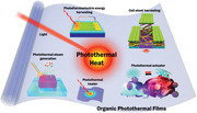
1. Introduction
Photothermal materials (PTMs) exhibit unique phenomena based on conversion of light to heat, which has attracted interest in the study of such highly intriguing phenomena in the condensed phase and the exploration of their application potential, ranging from photothermal therapy (PTT) and photothermal (PT)/photoacoustic (PA) imaging,[ 1 , 2 , 3 , 4 , 5 , 6 ] clean water harvesting,[ 7 , 8 ] photoactuation,[ 9 ] cell sheet engineering,[ 10 ] and energy harvesting.[ 11 , 12 ] The PT effect, or PA effect as originally defined,[ 13 , 14 ] is observed when photoexcited materials produce thermal energy via nonradiative vibrational relaxation of excited electrons. For example, free electrons in the metallic nanomaterials absorb light, creating a specific oscillation that produces a PT effect from the surface plasmon resonance (SPR) of electrons.[ 13 , 14 ] The thermal energy derived from the excited electrons is transferred to the lattice phonons and conducted throughout the material. Thus, numerous studies of metallic PTMs have focused on creating optimized plasmonic structures that promise high absorption of light at a certain wavelength to produce excited electrons.[ 1 , 15 , 16 ] In addition, the crystal structure, composition, shape, and size of the nano‐sized PTMs have been investigated to activate SPR electrons.[ 17 , 18 , 19 ] To date, SPR‐based Au nanoparticles (NPs) have shown the highest PT conversion efficiency (ηPT) of 100%,[ 20 ] while hybrid semiconducting polymer ferro‐therapeutic agents showed a slightly lower ηPT (98.9%).[ 21 ]
Furthermore, carbon‐based nanomaterials and hybrid nanocomposites have been reported with an improved ηPT over the years. Although carbonaceous nanomaterials and metallic nanomaterials have been examined by numerous researchers, these materials normally comprise NP‐shaped powders and are not readily fabricated into various shapes or thin films with large areas. Additional issues related to inorganic PTMs include biocompatibility and environmental safety.
Thus, many organic molecular PTMs (m‐PTMs), including molecular dyes such as cyanines (Cys) and croconaines (Crocs), have been investigated, particularly for PTT and photoacoustic therapy (PAT).[ 22 , 23 ] However, to apply m‐PTMs in PT devices that require film types, polymeric media are required, and thus the content of m‐PTMs in the film is rather limited, to lower ηPT from these films. Due to easy processability and low toxicity, polymeric PTMs (p‐PTMs) are explored for thin film applications.[ 24 , 25 , 26 , 27 , 28 , 29 , 30 ] Furthermore, polymers are intrinsically thermal insulators and flexible.[ 31 ] Therefore, recent efforts have been devoted to developing p‐PTMs. In particular, conjugated polymers (CPs) with long π‐conjugated backbones of contiguous sp 2‐hybridized carbon atoms display high absorption in the visible to NIR region and are easily photoexcited.[ 4 , 32 ] Thus, a variety of CPs, including poly(3,4‐ethylenedioxythiophene)s (PEDOTs),[ 29 , 30 , 33 , 34 ] polyanilines (PANIs),[ 35 , 36 ] and polypyrroles (PPys)[ 37 , 38 , 39 ] are potential candidate as p‐PTMs. However, NIR energy utilization is impeded by the narrow absorption bandwidth in the visible region and the low charge‐carrier mobility of polymers. Therefore, several strategies have been proposed to broaden the absorption spectra: 1) protonic acid doping and oxidative doping of CPs, 2) copolymerization of electronic donor–acceptors (D–As), and 3) hybridization with carbonaceous materials, metals, and metal oxides, as reported for PANIs, PPys, PEDOTs, polydopamines (PDAs), and other CPs.[ 4 ]
While many reviews of PTMs based on inorganic PTMs are available,[ 1 , 2 , 3 , 4 , 5 , 6 , 15 , 17 , 18 , 40 , 41 ] synthesis and PT mechanisms for thin film applications for organic PTMs remain rare.[ 31 , 42 ] Nonetheless, the PT applications using organic PTMs have dramatically increased since 2011. Furthermore, recent advances in the heat maneuvering and energy harvesting fields have led to the fabrication of PTMs as films, which integrate easily with other layers in a device. Thus, in this review, we first focus on PT films based on organic materials by summarizing the basic properties, such as the heat evolution and efficiency of the PT effect. Second, we highlight the state‐of‐the‐art synthesis of organic PTMs and discuss strategies for improving the high NIR absorption, color tunability, and eventually ηPT. Third, the emerging applications for organic PTMs are exemplified. The perspectives and challenges of PTMs for potential applications are discussed. For example, PT films can be used as wireless actuators, film heaters, energy harvesters, and harvesters for single cell and cell sheet, taking advantage of spatiotemporal control by the wavelength, intensity, diffraction, and polarization of light. Therefore, the application potential of PT films can be extended to various fields, not only those areas that have been developed for PT nanoparticles in solution, but also new areas, where spatiotemporal thermal engineering is required. We believe that PT films derived from noteworthy organic PTMs will become promising resources for thermal engineering to advance the science and technologies related to PT effects that utilize light stimuli such as a high degree of spatiotemporal control by the wavelength, intensity, and polarization of light.
2. Photothermal Characterization of Organic PTMs and Their Films
PT phenomena occur in two steps.[ 7 , 32 ] First, light energy is absorbed by the PTMs and the absorbed energy is partially or completely converted into heat through electronic excitation and nonradiative relaxation of the excited electrons to the ground state (S0). This first step is mediated by in three different mechanisms, depending on the material type: plasmonic (localized) heating of metal nanostructures, carrier generation and nonradiative relaxation of semiconducting materials (e.g., polymers and metal oxides), and thermal vibrational relaxation (thermalization) in conjugated molecules. Second, the generated heat energy is transferred from the hot side to the cold side of the materials or surrounding medium through phonon transfer.
Although free electrons are the key carriers in the metal atoms and their oxides (Figure 1 ), π electrons delocalized along the π‐conjugated bond of organic materials generally generate the major carriers that absorb light and create thermal energy. This process is attributed to the electrons in the π‐bonds that are more loosely bound (e.g., C=C π‐bond energy for ethene = 272 kJ mol−1) and much more weakly bound in extended delocalized π‐bonds with low band gaps, than those in the σ bonds (e.g., the C‐C bond energy for ethane = 439 kJ mol−1). Upon excitation with light beyond their band gap, the electrons of the organic PTMs are activated from S0 to the upper level (S1, S2, etc.) (Figure 1b).[ 7 , 32 ] When the electrons return to S0 via a nonradiative process, energy is released as heat. Therefore, energy level design of PTMs is important for effective PTMs leading to the desired pathway.
Figure 1.
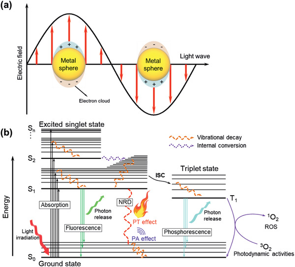
a) The oscillation of electron clouds in heavy metal based nanoparticle induced by light irradiation.[ 19 ] b) The Jablonski diagram illustrating the photophysical processes (energy transfer) of the conjugated material including the PT effect. Adapted with permission.[ 32 ] Copyright 2015, American Chemical Society. ISC, intersystem crossing; NRD, nonradiative decay; ROS, reactive oxygen species.
The excited electrons may undergo intersystem crossing (ISC) to reach triplet states by changing the electron spin orientation, where electrons return to S0 through a nonradiative process to release heat. However, this process competes with others, such as phosphorescence and photochemical reactions that are principally mediated by 3O2 producing radicals or O2 − and 1O2 (in the NIR‐II region), which have been applied to photodynamic therapy. In comparison with molecular materials, conductive polymers usually show more effective PT effect. A low bandgap and polaronic band in conductive polymers promote the PT process over other photophysical processes in Figure 1b, to increase the proportion of nonradiative process.
Thus, to obtain a high ηPT, the energy of excited electrons must not be consumed by other processes such as fluorescence, phosphorescence, chemical reaction, and self‐quenching. When a shorter wavelength of light is absorbed by materials, a higher probability of side processes is observed, and thus light in NIR region must be absorbed to achieve a high ηPT. Therefore, major strategies to design PTMs have emphasized a lower band gap by extending π‐conjugation, introducing an intramolecular D–A structure, and doping with the conjugated molecules.[ 7 , 32 ] Because the nonradiative decay (NRD) of the excited electrons is important, the NRD efficiency of the materials determines the PT conversion.[ 43 ] Notably, excited‐state intramolecular motions (EXIMs), such as rotation and vibration, enable the absorbed light energy to dissipate as heat, promoting PT conversion.[ 44 ] Thus, a D–A structured aggregation‐induced emission luminogen was reported as a PTM with boosted a NRD process in the solid state and aggregate state within NPs arising from the effective EXIMs.[ 43 , 44 ]
To estimate ηPT, the Grüneisen parameter (Γ) was used based on an initial pressure rise (p 0) in PA tomography.[ 45 ] The heat generated from the PT effect in tissue results in p 0, which creates acoustic waves. The Γ for tissue relates p 0 and light absorption as
| (1) |
where μa is the absorption coefficient of tissue, and F is the local light fluency. Using the isobaric volume expansion coefficient (β), specific heat capacity (C p), isothermal compressibility (κ), and mass density (ρ), Γ can be expressed as below:
| (2) |
The determination of Γ using PA and PT methods is complicated and Γ is inconsistent even within the same type of tissue.[ 46 ] Nonetheless, Γ has been used for PA materials and shows improved imaging properties by either increasing μa or tuning Γ.[ 47 ]
In the case of NPs or films containing PTMs, ηPT values have been reported using the temperature increase measured by IR sensors and thermometers. The ηPT value for a film is determined from the ratio of the photothermally converted thermal energy to the absorbed light energy by modifying the equation for the solution case.[ 26 , 30 , 48 ] The total energy balance of a system comprising a substrate and a PT film is defined as the sum of the heat for a PT transition (Q PT), heat for a substrate, and heat loss to the surrounding environment (Q surr) by heat conduction (Q cond), radiation (Q rad), and convection (Q conv) (Figure 2a) under light irradiation, as presented in Equation (3):
| (3) |
where i and j correspond to the system components and specific point (one pixel of a thermal imaging camera), respectively. The parameters m, T, and t represent the mass, temperature (the continuously mixed solution), and time, respectively. A large amount of heat must be generated at the irradiated area if Q surr is small.
Figure 2.
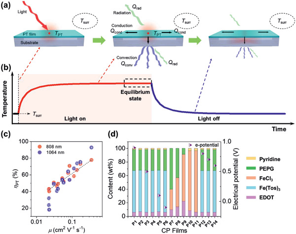
The scheme of the PT effect. a) Heat transfer in PT film following light irradiation. b) Change in the temperature of the irradiated area. c) ηPT for various PEDOT films as a function of Hall carrier mobility.[ 30 ] The sample numbers correspond to the PEDOT films prepared from the composition listed in (d). d) Compositions of the solution for the preparation of PEDOT films via SCP in (c). Tos represent for tosylate. (c) Reproduced with permission.[ 30 ] Copyright 2019, The Royal Society of Chemistry.
The sum of Q PT, the PT heat energy produced by light irradiation to the PT film, generates heat through electron‐phonon relaxation, which is determined using Equation (4), as follows:
| (4) |
where I 0 and Aλ are the laser power and absorbance at the light wavelength; Q sub is the amount of heat that dissipated following light absorption by the substrate in the absence of the PT film. Because a transparent (non‐PT) substrate is generally used, the absorbance of the substrate is very small. Therefore, Q sub is very small compared to Q PT and is negligible. Q surr is the amount of thermal energy released to the surrounding environment through heat convection, conduction, and radiation. It is assumed that Q surr increases linearly with temperature for the outgoing thermal energy within a small temperature range to minimize the factors of convection and radiation heat energy loss to the surrounding environment, resembling an isolated system and the heat capacity of the system is sufficiently large to diminish the two factors:
| (5) |
where h, a, T surr are the heat‐transfer coefficient, the surface area, and the surrounding temperature of the system, respectively. The maximum temperature (T max) of the PT film is obtained when the heat generated (input) upon light exposure is equal to the heat released (output) in the equilibrium state (Figure 2b):
| (6) |
where Q surr, max is the maximum Q surr in the equilibrium state. The heat‐transfer factor (ha)j is determined using a dimensionless temperature ratio term at specific point (θj) and time constant (τs,j) in the cooling part without light exposure:
| (7) |
| (8) |
Equations (6)–(8) can be substituted into Equation (3) and rearranged to yield:
| (9) |
The Q PT,j and Q sub,j terms become zero at the cooling part when the laser is turned off:
| (10) |
A linear relationship between t and ln θj with a slope of τs,j by integrating Equation (10) gives the following equation:
| (11) |
Finaly, the ηPT is determined by above equations:
| (12) |
Therefore, a strong absorption of light, a high temperature increase due to the PT effect (ΔT PT ), ΔT PT = T max – T surr, and a low thermal conductivity of the PT films are important parameters to obtain a high ηPT in PT films. The ηPT for a 180 nm‐thick PEDOT film was determined using the heat capacity of the PEDOT film, and ΔT PT over time during a cooling process after irradiation with an NIR laser.[ 30 ] The maximum ΔT PT of a substrate without the PEDOT film upon irradiation with the NIR laser was almost undetectable (<1 K), whereas the maximum ΔT PT values for the PEDOT film were found to be 127 and 143 K upon irradiation with an 808 nm (I 0 = 0.19 W) and 1064 nm (I 0 = 0.22 W) laser, respectively. Interestingly, ηPT ranged from 17% to 93% for PEDOT films with different oxidation (doping) levels and structural order of the polymer that was controlled by the polymerization condition and composition (Figure 2c,d).
The PT effect of organic films is strongly associated with the carrier concentration (p) and mobility (μ); thus, ηPT correlates with their indispensable electronic properties, such as electrical conductivity (σe) and density of state (DOS). As the doping level for CPs directly affects the electronic properties of the materials, increases in the oxidation level to populate polaronic states cause increased σe because of the higher p in the valence (p‐type material) states. Interestingly, μ of the CPs was strongly correlated with ηPT (Figure 2c), while p of the CPs was maximized when ηPT was ≈50%.[ 30 ] In principle, p is correlated to the DOS according to the Fermi–Dirac distribution function (f(E)) and the function of the DOSs (g V(E)) for p‐type materials.[ 49 ]
| (13) |
where E V is the top of the valence band. Thus, the DOS can be correlated to ηPT. Following the PT heat generation mechanism in a film (shown above), the DOS of the conduction and valence bands is a characteristic determinant. Because the increased degree of crystallinity of materials increases carrier delocalization through the conjugation network and π‐orbital overlapping in the π‐stacking direction, the change in crystallinity directly modifies the electronic band structure near the Fermi level (E F), as well as the DOS shape.[ 50 , 51 ] The PT effect is improved as the DOS at E F of PTMs becomes broader, which is achieved by increasing the degree of crystallinity of PTMs.
Since the DOS for semiconductive materials is related to the thermoelectric Seebeck coefficient (S TE), which is calculated using Equation (14) based on Mott's formula, the PT effect is enhanced in materials with a high S TE.
| (14) |
where k B is the Boltzmann constant and e is the unit charge. Equation (14) can be rewritten as an expression in terms of μ and DOS, as given by Equation (15).
| (15) |
To obtain a high crystalline ordering and to increase the DOS of p‐PTMs, the twisting angle of the polymer backbone should be minimized.[ 30 ] N‐containing polymers, such as PPys and PANIs, have a low degree of crystalline ordering due to twisting along the backbone, leading to poor π–π stacking. These polymers show a lower S TE, σe, and μ with a relatively lower ηPT compared to PEDOTs and polyselenophenes. In summary, a high light absorption and a high ΔT PT with a low thermal conductivity of the PT films are important parameters to obtain a high ηPT in PT films. Since PT effect is strongly associated with p and μ, the degree of crystallinity and structural order of PTMs in a film are also important to obtain a high ηPT in PT films. Therefore, a rational design for efficient PTMs should achieve: 1) a low band gap in conjugated molecules for enhancing nonradiative relaxation and thermalization in the NIR range, 2) a high packing density of conjugated units for a high light absorption, 3) a high degree of crystallinity and μ, and 4) a low heat loss to the substrate.
3. Organic PTMs in the Film States
3.1. Organic Molecular PTMs
Due to their intense absorption in the NIR range, NIR‐absorbing dyes, such as Cys, Crocs, diketopyrrolopyrroles (DPPs), and diimmoniums (DIs), have been explored for m‐PTMs.[ 52 , 53 , 54 ] These materials generally consist of long conjugated groups that are bridged between electron donors or donor coupled acceptors. Long alkyl or ionic groups are introduced as the substituents of donor or acceptor to improve the solubility and physical properties of the PTMs. The absorption properties of m‐PTMs are easily tuned by varying the donor units that are conjugated with the bridging group.
Cys consist of a lipophilic polyene bridge and two alkyl indocyanine moieties with an ionic terminal group (hydrophilic) possessing amphiphilic properties. The best known structure is indocyanine green (ICG), which consists of a polyene bridge and two 4‐(l,l,2‐trimethyl‐lH‐benzo[e]indolium‐3‐yl)butane‐l‐sulfonate groups. ICG was first synthesized by reacting molecule (1) with 1,4‐butane sulfone to produce molecule (2), followed by treatment with molecule (3) and the synthesis of a sodium salt (Figure 3a).[ 55 ] ICG absorbs the NIR light with a maximum absorption wavelength (λmax) at 780 nm and has been used in the clinic because it was approved for use in human subjects by the U.S. Food and Drug Administration in 1959.[ 56 ]
Figure 3.
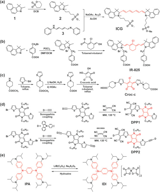
Synthesis of m‐PTMs. a) ICG,[ 55 ] b) IR‐825,[ 57 ] c) Croc‐c,[ 58 ] and d) DPP1 and DPP2.[ 59 ] e) Synthesis of IDI via oxidation of IPA.[ 54 ] The core part of the molecule is highlighted in red. DCB, 1,2‐dichlorobenzene; DMF, dimethylformamide; DCM, dichloromethane; MW, microwave.
ICG releases reactive oxygen species (ROS, 1O2) to exert anti‐tumor effects. However, ICG suffers from several major limitations, such as a low ηPT (≈9% max), low thermal stability, and light‐dependent optical properties which include photodegradation, discoloration, and λmax shift.[ 60 , 61 ] Thus, many other Cy derivatives have been developed by modifying the ICG structure. For example, a series of IR‐X, where X is the λmax of dyes in NIR region, were developed by modifying the polyene, the alkyl groups in the indole group, and counter ions, to improve application potential, such as tumor imaging and targeted therapy.[ 62 ] For example, IR‐825 was synthesized from cyclohexanone as a bridge and 2,3,3‐trimethyl‐4,5‐benzo‐3H‐indole as the indocyanine group (Figure 3b).[ 57 ]
Extensive effort has been devoted to encapsulating ICG and Cys in NPs including liposomes,[ 63 ] micelles,[ 57 , 64 ] and polymers,[ 65 ] for theranostic applications.[ 32 , 60 , 63 ] However, Cys have rarely been developed for a thin film application, mainly due to their poor compatibility with polymers and limited stability in the film state.
Croconic acid, 4,5‐dihydroxycyclopentenetrione, contains two hydroxyl groups, which have been used to synthesize Crocs via a one‐pot condensation reaction of croconic acid with electron‐rich molecules (Figure 3c).[ 66 , 67 , 68 ] These D–A–D type zwitterionic structures are quite similar to the well‐known squaraines; however, the λmax of Crocs redshifted by approximately 100 nm compared with the corresponding squaraines.[ 69 , 70 , 71 ] Crocs exhibit narrow and strong NIR absorption with high molar extinction coefficients (105 M−1 cm−1).[ 58 ] The absorption properties of Crocs are easily tuned by varying the donor and substituents on the donor units that are conjugated with the croconium core. Crocs generally show good photostability[ 69 ] and generate PT heating without producing 1O2 because of their low ISC to the triplet state (3O2).[ 67 , 68 ] A water‐soluble croconium dye, Cros‐c, was obtained by condensing croconic acid with 2‐(4‐carboxylic‐piperidylamino)thiophene to produce 2,5‐bis[(4‐carboxylic‐piperidylamino)thiophenyl]‐croconium.[ 58 ] The water solubility of PTM is useful in preparing a therapeutic agent for PTT and PAT applications or in green solution‐process. Cros‐c showed a sharp and strong absorption at 800 nm and little absorption in visible region in water (Figure 4g). The Croc‐c doped in polyvinyl alcohol film exhibited similar NIR absorption as Croc‐c dissolved solution and excellent photostability when incorporated in NIR‐blocking plastic filters.[ 58 ]
Figure 4.
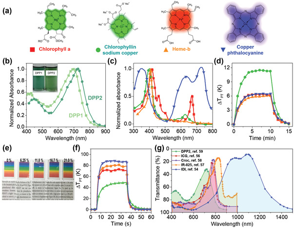
Absorption spectra of m‐PTMs described in Figure 3. a) Chemical structures of 4 porphyrinic compounds: chlorophyll a (red), chlorophyllin sodium copper (green), heme‐b (orange), and copper(II) phthalocyanine (blue).[ 72 ] b) DPP1 and DPP2 in dichloromethane (3 × 10⁻⁶ m).[ 59 ] Inset: A photo image of the solutions. c) Normalized absorption spectra and d) ΔTPT of the compounds in (a) upon exposure to solar light. The symbols in (c,d) correspond to (a). e) Photo images of transparent IDI‐PES films with varying IDI content (wt%) on a glass slide with a rainbow color image and a letter image underneath. f) ΔTPT of the film containing 16.7% IDI in PES on a 50 µm‐thick PET film (red), 170 µm‐thick glass slide (green), and 60 µm‐thick PDMS film (blue), along with the ΔTPT of the 21.0 wt% IDI‐PES film on a 50 µm‐thick PET film (orange).[ 54 ] g) Transmittance of the m‐PTMs. a,c,d) Reproduced with permission.[ 72 ] Copyright 2020, American Chemical Society. b) Reproduced with permission.[ 59 ] Copyright 2016, Wiley‐VCH. e–g) Reproduced with permission.[ 54 ] Copyright 2020, Wiley‐VCH. g) Reproduced with permission.[ 56 ] Copyright 2011, Elsevier. Reproduced with permission.[ 57 ] Copyright 2013, Wiley‐VCH. Reproduced with permission.[ 58 ] Copyright 2008, Elsevier. Reproduced with permission.[ 59 ] Copyright 2016, Wiley‐VCH.
DPP‐based m‐PTMs have emerged by introducing donor units (triphenylamine, carbazole, or ferrocene), coupling more than one DPP unit (acceptor), or extending π‐conjugation through the 3‐ and 6‐positions of DPP.[ 53 ] For example, NIR‐absorbing low band gap DPPs were synthesized by bridging tetracyanobutadiene with carbazole‐functionalized DPPs using the Pd‐catalyzed Sonogashira cross‐coupling reaction (Figure 3d).[ 59 ] The absorption of the bis‐carbazole modified DPP (DPP2) exhibited a greater redshift than the mono‐derivative (DPP1) (Figure 4b).
As an organometallic PTM, porphyrinic compounds have been developed significantly and mixed with a binder polymer, such as polymethylmethacrylate or polyethylene glycol (PEG), to form films.[ 72 ] The content of m‐PTMs in the polymer was controlled to obtain an average visible transmittance (AVT) of 64.5–85.5% in the wavelength range of 380–760 nm. The ηPT of the film was determined from the cooling region to be 20.9%, 36.9%, 16.1%, and 16.6% at 64.5% AVT, for chlorophyll a, chlorophyllin sodium copper, heme‐b, and copper(II) phthalocyanine (Figure 4a,c), respectively. The highest ηPT of 36.9 % (chlorophyllin sodium copper) was determined from a ΔT PT of 11.30 K upon exposure to solar light (1 Sun, 100 mW cm–2). However, the ΔT PT from the above m‐PTMs was low (Figure 4d) due to their low ηPT. Furthermore, most of them exhibit significant absorption of visible light, limiting their application in invisible PT systems.
Diimmonium salts (IDs), on the other hand, are much more transparent in the visible region, while they absorb IR light due to a low band gap.[ 73 ] For example, an isobutyl substituted diimmonium salt (IDI, Figure 3e),[ 54 ] synthesized by oxidizing the corresponding neutral amine, N,N,N′,N′‐tetrakis[4‐(diisobutylamino)phenyl]‐1,4‐phenylenediamine (IPA), affords a highly transparent film, when it was doped in a transparent polymer, such as polyethersulfone (PES) and polydimethylsiloxane (PDMS). A 0.4 μm‐thick PES film containing 21.0 wt% IDI showed a ΔT PT of 80 K and an ηPT > 75% due to a charge resonance intervalence state originating from the delocalized dication state resulting in a low band gap (0.91 eV). The ηPT is much higher than that obtained for the NIR dyes developed to date. Furthermore, the film containing 16.7% IDI showed a transmittance of >90% and revealed the full color of the underlying color image (Figure 4e).
The structures and absorption spectra for some representative m‐PTMs are compared in Figure 4g. Although most of the m‐PTMs show a strong absorption tail in the visible range, IDI shows a low level of absorption in the visible range and broad NIR absorption, which might be beneficial for transparent PT applications.
3.2. Polymeric PTMs
The m‐PTMs have a large structural variation with spectral selectivity, but they are limited for a film type PT system, as described in the previous section.[ 54 , 58 , 73 ] On the other hand, p‐PTMs have advantages over m‐PTMs because they can be prepared as a film using a simple solution process.[ 26 , 28 , 29 , 30 ] Furthermore, the π‐bonds of p‐PTMs are delocalized over their backbone, which might improve carrier transport and provide multifuctionality by combining intrinsic σe and optical properties. Notable p‐PTMs include 1) poly(3,4‐ethylenedioxythiophene) (PEDOT) and poly(3,4‐ethylenedioxyselenophene) (PEDOS) (Figure 5a),[ 29 , 30 ] 2) PANIs[ 35 , 36 ] and PPys,[ 37 , 38 , 39 ] and 3) polymers prepared from D–A type monomers. Although the PT effect was not characterized, the first example of a p‐PTM can be found from the poly(3‐hexylthiophene)/PEDOT:polystyrene sulfonate (PSS) film, which was used as a PT detector.[ 74 ] A photovoltage of ≈0.6 mV was detected for the polymer film in the lateral‐type field effect transistor upon irradiation with a 630 nm laser at a power of ≈1 mW.
Figure 5.
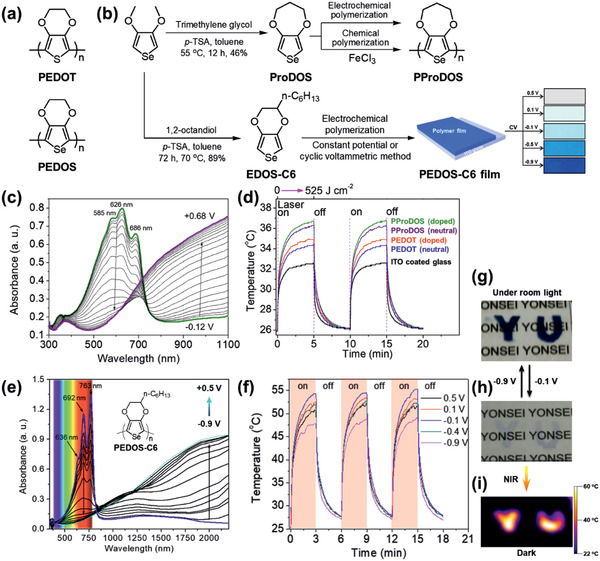
a) Structures of PEDOT and PEDOS.[ 25 ] b) Synthesis of ProDOS and EDOS‐C6, followed by polymerization into a film and by cyclic voltammetric doping controls. c) In situ spectroelectrochemistry of the PProDOS film. d) PT switching of the PProDOS and PEDOT films (doped and dedoped states) upon irradiation with an 808 nm laser. e) In situ spectroelectrochemistry of the PEDOS‐C6 film prepared using the CPM and f) corresponding PT switching with different doping levels upon irradiation with an 808 nm laser.[ 26 ] Photo images of g) dedoped and h) doped PEDOS‐C6 films. i) IR camera image upon exposure to NIR. b–d) Reproduced with permission.[ 25 ] Copyright 2011, American Chemical Society. b,e–i) Reproduced with permission.[ 26 ] Copyright 2013, Wiley‐VCH.
A poly(3,4‐propylenedioxyselenophene) (PProDOS) film was reported in 2011 as a p‐PTM.[ 25 ] The ProDOS monomer (Figure 5b), which is synthesized from 3,4‐dimethoxyselenophene with trimethylene glycol, was polymerized and processed as a low band gap film via electrochemical or chemical polymerization. The absorption of a 100 nm‐thick film in the NIR region was maximized in the electrochemically doped state (+0.68 V vs Ag/AgCl) (Figure 5c). With a laser power density (I pd ) of 0.7 W cm–2, the PProDOS film with an optimized doping state and film composition (Figure 5d) showed a ΔT PT of 10.7 K[ 25 ] and ηPT of 19.8%,[ 26 ] which was comparable to inorganic materials such as Au nanoshells (13%),[ 75 ] Au nanorods (21%),[ 75 ] CdTe quantum dots (14%),[ 76 ] and Cu9S5 nanocrystals (25.7%)[ 77 ] in early studies. Notably, the PProDOS film on ITO glass showed a color change according to its oxidation state, providing visible to NIR electrochromism and suggesting that it may produce an electrochemically tunable PT effect.
Polyselenophenes with increased ordering of polymer chains afforded a high ηPT as reported for poly(hexyl‐3,4‐ethylenedioxyselenophene)s (PEDOS‐C6).[ 26 ] The morphology and electronic properties of the PEDOS‐C6 film were controlled by the polymerization method followed by doping (Figure 5b). The PEDOS‐C6 film prepared using the constant potential method (CPM) and partially doped (at –0.1 V vs Ag/AgCl) showed a higher ηPT of 42.5% than that using a cyclic voltammetric method (ηPT of 31.8%).[ 26 ] This result was ascribed to homogeneous film formation and the alignment of polymer chain from the CPM to produce a PEDOS‐C6 film with high absorption in the polaron and bipolaron regions (Figure 5e). With an I pd of 2.33 W cm–2, the optimized PEDOS‐C6 film showed a ΔT PT of >30 K which was higher than the PProDOS film (Figure 5f). As shown in Figure 5e,h, the doped PEDOS‐C6 film was quite transparent, and thus it provided the most transparent PT film among the p‐PTMs. The PEDOS‐C6 film showed transparent to visible electrochromism, which was hot and cold, respectively, under NIR light (Figure 5g‐i).
While the polyselenophenes provide a high ηPT, the synthesis of PEDOS and its derivatives is not trivial. On the other hand, based on the studies of PProDOS and PEDOS‐C6, the ηPT is substantially affected by the doping states, ordering of polymer chains, and homogeneity of the film morphology, which are controlled by the polymer structure, film preparation method, and doping. Thus, easily accessible polymers, PEDOTs, and other heterocyclic polymers have been extensively studied since then.
For example, PEDOT films with an improved ηPT of 50–93% were reported by controlling the polymerization composition and condition to vary the π–π intermolecular ordering and doping states of polymers (Figure 2c).[ 28 , 30 ] PEDOT films were prepared using solution casting polymerization (SCP) with a solution containing the monomer (EDOT), oxidant, pyridine, and polymeric surfactant (PEPG) (Figure 6a). PEDOT films showed large absorption in the NIR region, which depended on the composition of the polymerizable solution (Figure 6b).
Figure 6.
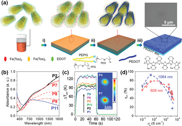
a) Schematic presentation of the synthesis of the highly crystalline PEDOT film using SCP.[ 30 ] i) Spin‐coating of EDOT/Fe(Tos)3/pyridine/PEPG in n‐butanol solution onto a substrate; ii) Heating at 60 °C for polymerization; and iii) washing with ethanol for two times to obtain a highly crystalline PEDOT film. Inset: Scanning electron microscopy (SEM) image of P4. b) UV–vis‐NIR spectra of PEDOT films prepared from different polymerization solutions. c) Evolution of the temperature increase in PEDOT films upon exposure to an NIR laser (808 nm, 0.19 W) with the light switched off after 60 s. Inset: IR images of PEDOT films after irradiation for 1 min. d) Correlation of ηPT at 808 nm (red dot) and 1064 nm (blue square) with σe of polymer films. a–d) Reproduced with permission.[ 30 ] Copyright 2019, The Royal Society of Chemistry.
As the thermal conductivity of PEDOT films is generally low (≈1 W m−1 K−1),[ 78 ] the photothermally generated heat may be trapped within the film; thus, ΔT PT (Figure 6c) and ηPT might be high since the surrounding air is a very poor heat conductor. For example, a 180 nm‐thick PEDOT film, with an optimized doping state and film composition, exhibited a ΔT PT >100 K upon irradiation with an 808 nm laser (0.19 W). The ηPT of PEDOTs increased with the increasing σe of PEDOTs at the low σe, but decreased with increasing σe at the high σe region to yield a maximum ηPT of 93% at σe of 0.247 S cm−1 upon exposure to 1064 nm laser (Figure 6d). As described in Section 2, the ηPT was linearly correlated with the μ of PEDOT films (Figure 2c).
Other CPs, such as PANI and PPy, have also been employed for PTMs. PANI was synthesized using aniline with an oxidant to produce an insoluble PANI in the doped state (emeraldine salt, ES) (Figure 7a).[ 35 ] The synthesized ES form was dedoped with a base to afford the more soluble neutral type of PANI (emeraldine base, EB), which is used to prepare NPs and films of PANI (Figure 7b). PANI is generally nontoxic toward normal cells, and PANIs in the EB state are conveniently doped with dopants (i.e., strong acids, Lewis acids, transition metals, etc.). This doped polyaniline (ES) absorbs NIR light and produces heat.[ 35 , 36 , 79 ] Because of the acidic/oxidative conditions near cancer cells, the NPs in the EB state injected into the body become oxidized in cancer cells exhibiting a color change to ES state. The cancer cells treated NPs in the ES state were ablated through laser irradiation by the PT effect of PANI in the ES state, which provided the first example of a PT theranostic method with CPs in 2011.[ 35 ] Since then, PT applications of PANI, oligoaniline, and other CP‐based nanostructures have been extensively reported.[ 79 , 80 , 81 , 82 , 83 ]
Figure 7.
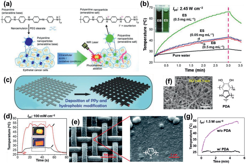
a) Schematic illustrating the preparation of PEGylated PANI NPs and their application in the PT ablation of epithelial cancer cells following NIR laser irradiation.[ 35 ] b) PT switching effect of the irradiation of pure water, and the EB and ES states of PANI NPs upon irradiation with an 808 nm laser. c) Schematic illustrating the preparation of the PPy‐coated SS mesh as a light‐to‐heat conversion membrane.[ 38 ] d) PT effect of the original SS mesh (black) and the PPy‐coated SS mesh (red) upon irradiation with solar light. Insets: IR images of the PPy‐coated and original SS meshes under solar light irradiation. e) SEM images of the PPy‐coated polypropylene mesh at different magnifications.[ 99 ] Inset: chemical structure of PPy. f) Field emission (FE)‐SEM image of the PDA‐modified nanofibers.[ 98 ] The chemical structure of PDA. g) PT effect of the nanofibers with and without PDA‐modification upon irradiation with an 808 nm laser. a,b) Reproduced with permission.[ 35 ] Copyright 2011, Wiley‐VCH. c,d) Reproduced with permission.[ 38 ] Copyright 2016, Wiley‐VCH. e) Reproduced with permission.[ 99 ] Copyright 2017, The Royal Society of Chemistry. f) Reproduced under the terms of a CC‐BY license.[ 99 ] Copyright 2019, The Authors. Published by Springer Nature.
PPys have also been explored as PTMs, due to their broadband absorption spectrum in their bipolaronic state. PPys have been coated or deposited on various substrates, including (non)conductive and porous substrates. Recently, PPy was uniformly deposited onto meshes by electropolymerization, to produce a PPy‐coated stainless steel (SS) mesh for solar steam generation (Figure 7c–e).[ 38 ] As shown in Figure 7d, the ΔT PT of the mesh increased to 28 K upon irradiation with solar light.
Melanin, a family of pigments present in various plants and animals, shows a strong absorbance of NIR light and thus can be potentially applied as a PTM.[ 84 ] In a recent report, natural black sesame melanin (BSM) was employed as a PTM, and a ΔT PT of 18 K was observed from a BSM NP solution (1 mg mL−1, pH 12) irradiated with an NIR laser (808 nm) for 10 min.[ 85 ] BSM is nontoxic toward normal cells and possesses good biocompatibility. PDA, a melanin‐like polymer,[ 86 , 87 ] provides a useful platform[ 88 , 89 , 90 ] for applications ranging from bioadhesives,[ 91 ] enzyme immobilization,[ 92 ] antibacterials to environmental remediation,[ 93 , 94 ] and energy conversion.[ 95 , 96 ] For example, PDA nanofibers fabricated on the surface of lipid nanotubes exhibited a large ηPT.[ 97 ] A multiple stimuli‐responsive PDA‐modified nanofibrous mat showed a ΔT PT of 24.9 K upon irradiation with an NIR laser (808 nm) (Figure 7f,g).[ 98 ]
DPP potentially represents an electron‐deficient bridging group to extend the π‐conjugation length,[ 100 , 101 ] and thus a tunability of the band gap of D–A type CPs into the NIR region via copolymerization with aromatic heterocycles such as various thiophene derivatives (monothiophene, bithiophene, and benzodithiophene) has been provided using the Stille coupling reaction.[ 53 , 101 , 102 , 103 , 104 , 105 , 106 , 107 , 108 ] For example, a vinylene bridged DPP polymer (DPPV) was synthesized from monomers (4) and (5) (Figure 8a).[ 105 ] Interestingly, DPPV showed a higher absorption in the NIR region than its analog DPPT, in which the vinylene bond is absent. In addition, co‐precipitation method was used for the DPPV and a biodegradable amphiphilic polymer to form a NP with good water solubility, and this biodegradable NP showed enhanced a PA imaging and a PTT effect. Recently, D–A1–D–A2‐type DPP polymer (PDPPTDQ) was synthesized, where D, A1, and A2 are thiophene, DPP, and thiadiazoloquinoxaline, respectively (Figure 8c).[ 108 ] Compared with its analog PDPPTh, a D−A alternating backbone structure (D = thiophene and A = DPP), PDPPTDQ exhibited a lower band gap energy, leading to absorption in the NIR‐II region, thanks to the presence of a much stronger electron‐withdrawing A2 in the polymer backbone (Figure 9i).
Figure 8.
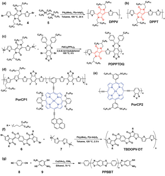
Synthesis and chemical structure of p‐PTMs. a) DPPV and b) DPPT.[ 105 ] c) PDPPTDQ.[ 108 ] d) PorCP1.[ 109 ] e) PorCP2.[ 110 ] f) TBDOPV‐DT.[ 111 ] g) PPBBT.[ 114 ] The core part of the molecule is highlighted in red or blue.
Figure 9.
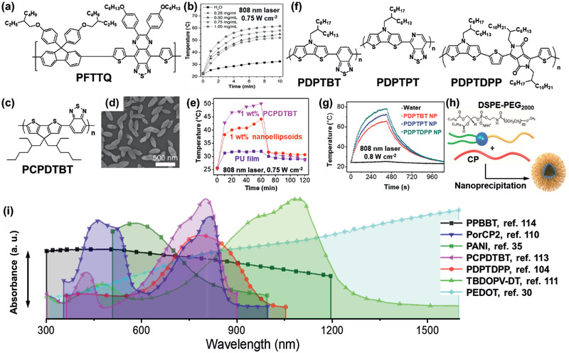
Chemical structure and absorption properties of p‐PTMs. a) PFTTQ.[ 112 ] b) PT effect of PFTTQ NPs with various NP concentrations. c) PCPDTBT.[ 113 ] d) SEM image of nanoellipsoids. e) PT effect of the PU nanocomposite films. f) PDPTBT, PDPTPT, and PDPTDPP.[ 104 ] g) PT effect of the NPs of PDPTBT, PDPTPT, and PDPTDPP. h) Schematic illustration of nanoparticle formation. i) Absorption spectra of the p‐PTMs in solutions or film states. b) Reproduced with permission.[ 112 ] Copyright 2014, Wiley‐VCH. d,e,i) Reproduced with permission.[ 113 ] Copyright 2018, Elsevier. g–i) Reproduced with permission.[ 104 ] Copyright 2017, American Chemical Society. i) Reproduced with permission.[ 35 ] Copyright 2011, Wiley‐VCH. Reproduced with permission.[ 110 ] Copyright 2016, Wiley‐VCH. Reproduced with permission.[ 111 ] Copyright 2017, American Chemical Society. Reproduced with permission.[ 30 ] Copyright 2019, The Royal Society of Chemistry.
Other PT polymers were designed as a D–A structure bridged with a π‐linker in polymer backbone, to introduce ICT along the backbone, resulting in redshift in absorption.[ 109 ] For example, D–A type porphyrin‐based CPs (PorCP1 and PorCP2) were reported (Figure 8d,e). Because of the extended D‐A conjugation along the backbone, the PorCP2 showed a redshifted broad Q band up to 800 nm and increased extinction coefficient.[ 110 ] Through nanoencapsulation, a large number of PorCP2 molecules were densely packed in a single NP to produce favorable NRD, good photostability, and the highest ηPT of 63.8% among porphyrin based polymer NPs.
Recently, thiophene‐fused benzodifurandione polymer (TBDOPV‐DT) was synthesized via the Stille coupling between TBDOPV acceptor (6) and bithiophene donor (7) (Figure 8f).[ 111 ] The absorption spectra of a spin‐coated polymer film (thickness ∼13 nm) displayed a π−π* transition at 477 nm and a strong NIR‐II absorption at 1093 nm (Figure 9i) arising from the ICT. ηPT of the TBDOPV‐DT film was 50.5%, and the ΔT PT ranged from 25 K to 86 K upon exposure to a 1064 nm laser at a power ranging from 0.27 W to 0.98 W, respectively. Poly[9,9‐bis(4‐(2‐ethylhexyl)phenyl)‐fluorene‐alt‐co‐6,7‐bis(4‐(hexyloxy)phenyl)‐4,9‐di‐(thiophen‐2‐yl)thiadiazoloquinoxaline], PFTTQ, is also known as a PT polymer, which contains a highly electron‐rich fluorene unit and a highly electron‐deficient thiadiazoloquinoxaline unit, synthesized by Suzuki coupling. The PFTTQ NPs fabricated through a precipitation method using 1,2‐distearoylsn‐glycero‐3‐phosphoethanolamine‐N‐[amino(polyethylene glycol)‐2000 (DSPE‐PEG2000) as a surfactant as the encapsulation matrix showed a ΔT PT of 20 K within 3 min after exposure to an NIR laser (Figure 9a,b).[ 112 ] Poly[2,6‐(4,4‐bis‐(2‐ethylhexyl)‐4H‐cyclopenta[2,1‐b;3,4‐b′]dithiophene)‐alt‐4,7(2,1,3‐benzothiadiazole)], PCPDTBT, was prepared as nanoellipsoids with octanoic acid via emulsification (Figure 9c,d).[ 113 ] By adding the nanoellipsoids into an elastomeric polyurethane (PU), the resulting PU nanocomposite films showed a ΔT PT of 19 K upon irradiation with solar light for 60 min (Figure 9e). Other D‐A types of p‐PTMs have been reported using 4H‐dithieno[3,2‐b:2′,3′‐d]pyrrole (DTP) as a planar donor and benzothiadiazole (BT) derivatives and DPP as electron‐deficient acceptors via the Stille coupling (Figure 9f). Waster dispersible NPs were prepared via nanoprecipitation using DSPE‐PEG2000 as a surfactant to achieve highly efficient PA and PT performance in killing cancer cells (Figure 9g–h).[ 104 ]
Recently, poly(2‐phenyl‐benzobisthiazole) (PPBBT) was synthesized via click condensation reaction between monomers (8) and (9) (Figure 8g).[ 114 ] PPBBT showed a broad absorption spectrum in UV‐Vis‐NIR range similar to a single‐wall carbon nanotube (Figure 9i). PPBBT‐based water‐soluble and biocompatible NPs generated a ΔT PT of 25 K within 5 min upon exposure to an NIR laser and exhibited ηPT of a 32.4%, which maintained good photostability. Although many previous reports have described the clinical use of CPs for the effective eradication of tumors, the clinical use of these CPs remains controversial because of their poor biodegradability and potential toxicity to the human body.
4. Application Potential
Although the applications of PTMs have been investigated for more than 50 years, organic PTMs were mainly applied in PT deflection spectroscopy[ 115 ] and laser ablation until 2005.[ 24 , 116 ] Since then, their applications have been extended to precise therapeutic and imaging technology utilizing the localized heat generated at the laser‐exposed area. Furthermore, they have been applied to organic solar energy harvesting devices, sensors, and many other emerging technologies including photoactuators, desalination, and photoablation. In particular, application to NIR laser treatment (PTT, photodynamic therapy, and PA imaging) has emerged as a promising technology, due to its controllable operation of therapeutic moieties (e.g., heat, reactive oxygen species and drugs), noninvasive signal detection, high spatiotemporal resolution, and low photodamage, without affecting normal cells.[ 2 , 3 , 117 ] Initially, m‐PTMs, which mainly absorb the first biological window (NIR‐I, 700–950 nm), were explored and processed as NPs composed of m‐PTMs.[ 118 ] However, usage of light within the second biological window (NIR‐II, 1000–1350 nm) is more effective than the NIR‐I region, because of the lower absorption of water in NIR‐II, high light permissibility to skin (1 W cm−2 for 1064 nm and 0.33 W cm−2 for 808 nm) and lower light scattering by blood corpuscles and tissues which are the major light‐tissue interactions.[ 119 ] Thus, PTMs absorbing light within the NIR‐II region have emerged as a solution for PTT and for various applications.[ 21 ]
As a thin film in spatiotemporal thermal engineering, a PT layer functions as a light absorber and heater to 1) sense and attenuate NIR radiation, 2) evaporate water on a PT surface, 3) promote the thermal response of the contacting layer to lead actuation, 4) facilitate the thermal reaction at the substrate or PT layer, etc. On the other hand, the PT layers provide active carriers that can generate electricity via photovoltaic (PV), photothermoelectric (PTE), piezoelectric, and photo–mechanical mechanisms, enabling the PT layer to serve as a photodetector and an energy harvester. As presented in Figure 10 , a device structure can be as simple as a single layer, in that a PT film is used as a heater that consists of a single free‐standing PT film or a PTM or its composite‐coated film on a passive substrate. The heat generated from this film can be used for NIR sensors, desalination, and bacterial killing. In bilayer or multilayer applications, PT films are coated onto thermally responsive or reactive layers. For example, a PT actuator is assembled with a thermally responsive layer. Furthermore, the PT film can be coated onto a conductive layer to harvest energy by PT conversion.
Figure 10.
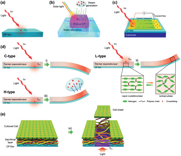
Potential applications of PT films. Schematic illustrating the generation of thermal energy in PT films derived by the PT effect upon light irradiation or the simultaneous action from thermal energy transfer to the combining substances on PT films. a) PT film heater. b) Solar water evaporator. c) PTE energy harvester. d) Three bending mechanisms of PT actuators according to their structures. i) Expansion of the thermally responsive elastomer layer (C‐type), ii) reduction in the volume of the phase change liquid‐crystalline layer (L‐type), and iii) water evaporation of the humidity‐responsive layer (H‐type). e) Light triggering cell sheet harvesting. iv) Unfolding process of the thermally sacrificial layer (collagen) to dissociate into aqueous media upon selective PT heating.
The ΔT PT of the PT layer by light exposure can be estimated from the ηPT of a PTM and the intensity of light according to Equation (16), which is derived from Equation (12)
| (16) |
However, other parameters such as the thickness and morphology of the film, wavelength of the light illumination, and Q sub may affect the ΔT PT of the PT film. Furthermore, m‐PTMs are difficult to process without dispersing them in a polymer binder and these films have evolved a low ΔT PT,[ 72 ] possibly due to the limited content of m‐PTMs and their low carrier mobilities. One exception is the IDI dispersed polymer film.[ 54 ] The 16.7 wt% IDI‐PES film on a 60 µm‐thick PDMS layer showed a ΔT PT of 87 K in 5 s by exposing the film to a 1064 nm laser (0.23 W) (Figure 4f). This can be ascribed to the high ηPT (75.2%) and transparency of the film. Therefore, it is interesting to review and compare the reported ΔT PT values for different PTMs, especially for p‐PTMs.
As a first example of a PT film, the 100 nm‐thick PProDOS film coated onto ITO glass showed a ΔT PT greater than 13 K upon irradiation at an 808 nm laser (I pd of 0.7 W cm−2).[ 25 ] The ΔT PT increased to 30 K when PProDOS was replaced with transparent PEDOS‐C6[ 26 ] upon irradiation at a higher I pd (Figure 5f). A PEDOT film with a high ηPT of 93% was reported by optimizing the degree of crystallinity and doping state, which reached ΔT PT >120 K (Figure 6c).[ 30 ]
Figure 11a shows the correlation of ΔT PT with ηPT upon exposure to different light sources and summarizes the state‐of‐the‐art PT films summarized in Table 1 . In general, the higher the ηPT, the higher the ΔT PT that is observed (Region I). However, it is noteworthy that some PEDOTs show higher ΔT PT values (Region II), possibly due to the improved μ in highly ordered polymer chains, as described in Section 3. The ηPT value of the PTMs roughly shows a linear relationship with their λabs (Figure 11b) under the condition that the excitation sources for PT experiments were different for each samples. The PEDOT film (No. 6) shows the state‐of‐the‐art ΔT PT of the PTMs exposed to a light source with different wavelengths (Figure 11c). While the MXene (Ti3C2Tx)@PDA‐PU composite (No. 10) shows the highest ηPT in the visible region, the p‐PTM, such as PEDOTs, shows the highest ηPT in the NIR region. Starting from an ηPT of 13% for PProDOS in 2011 (No. 5), an ηPT of >90% for p‐PTMs has been reported in 2019. Furthermore, light excitation at a short wavelength in the visible region is shifted to the NIR region to reduce unwanted side reactions of p‐PTMs and IDI (No. 15). Thus, PT heaters working in the NIR‐II region are now available, which will lead a substantial progress in PT science and engineering. The state‐of‐the‐art PTMs are summarized in Table 1.
Figure 11.

a) The correlation of ΔTPT with ηPT for various PTMs upon exposure to different light sources. The correlation of state‐of‐the‐art ηPT of the PT films with b) λabs and c) λPT exposed to a light source at different wavelengths. Sample numbers correspond to the sample numbers in Table 1.
Table 1.
Summary of the benchmark PTMs and their applications
| Application a) | Sample number | Organic PTMs | λabs [nm] b) | ε c) | σe [S cm−1] d) | λPT [nm] e) | ΔT PT [K] f) | ηPT [%] | Output | Performance | Ref. |
|---|---|---|---|---|---|---|---|---|---|---|---|
| PTH | 1 | Chlorophyll a | 415 | 2.3 g) | Solar | 6.13 | 20.9 | [ 72 ] | |||
| 2 | Chlorophyllin sodium copper | 400 | 6.2 g) | Solar | 11.3 | 36.9 | [ 72 ] | ||||
| 3 | IDI | 1130 | 1.3 g) | [ 54 ] | |||||||
| 4 | IDI‐PES | 1135 | 0.68 h) | 1064 | 87 | 75.2 | |||||
| 5 | PProDOS | 626 | 0.70 h) | 0.001 | 808 | 10.7 | 19.8 | [ 25 ] | |||
| 6 | PEDOT | 1250 | 0.21 h) | 0.247 | 1064 | 143 | 93 | [ 30 ] | |||
| 7 | PU–PPy | Solar | 50 | 73.9 | [ 148 ] | ||||||
| 8 | MXene@PDA‐PU | Solar | 63.5 | 90.1 | [ 149 ] | ||||||
| 9 | PVPS:PANI | ≈700 | 808 | 30 | – | [ 150 ] | |||||
| 10 | AgNP@MXene‐PU | 470 | Solar | 111 | – | [ 151 ] | |||||
| 11 | PDA coated mat | 980 | 808 | 24.9 | – | [ 98 ] | |||||
| 12 | TBDOPV‐DT | 1102 | 1.1 g) | [ 111 ] | |||||||
| 13 | TBDOPV‐DT | 1093 | 1.6 h) | 1064 | 107 | 50.5 | |||||
| PTW | 14 | IDI | 1130 | 1.3 g) | 1064 | 87 | 75.2 | ηPTW i) (νw j)) | 68.8 (3.65) | [ 54 ] | |
| 15 | IDI‐PES | 1135 | 0.68 h) | ||||||||
| 16 | PPy‐coated air‐laid paper | 400−1300 | 0.45 h) | Solar | 57.3 | – | ηPTW i) (νw j)) | 81.9 (1.41) | [ 122 ] | ||
| 17 | PPy‐PVDF | 300−2500 | Solar | 53 | – | ηPTW i) (νw j) ) | 93.8 (1.70) | [ 121 ] | |||
| PTA | 18 | IDI | 1130 | 1.3 g) | [ 54 ] | ||||||
| 19 | IDI‐PES | 1135 | 0.68 h) | 1064 | 87 | 75.2 | θb k) | 75 | |||
| 20 | PEDOT | 1300 | 0.12 h) | 1000 | 808 | 106 | 50 | θb k) | 150 | [ 29 ] | |
| 21 | PANI (ES)/LCE | 875 | 0.0082 g) | 808 | 112 | – | θb k) | – | [ 36 ] | ||
| 22 | RGO‐g‐P3HT | 581 | 532 | 40 | 82 | θb k) | 30 | [ 128 ] | |||
| 23 | f‐BNNS/PEDOT:PSS/PNIPAM | 0.0004 | 808 | 59 | – | θb k) | – | [ 152 ] | |||
| 24 | GO–PDA | IR | 32 | – | θb k) | 120 | [ 130 ] | ||||
| 25 | PDA‐RGO/NOA‐63 | 800 | 0.012 h) | 812 | – | – | θb k) | 80 | [ 129 ] | ||
| PTE | 26 | PEDOT | 1064 | 0.34 h) | 940 | Solar | 63 | 56 | PFPTE l) | 690 | [ 30 ] |
| 27 | PEDOS‐C6 | 763 | 1.1 h) | 335 | 808 | 30 | 42.5 | PFPTE l) | 354.7 | [ 26 ] | |
| 28 | Poly[Cux(Cu‐ett)]:PVDF | 808 | 76.1 | – | PFPTE l) | – | [ 146 ] | ||||
| 29 | PTII | 1369 | 0.022 | 1700 | 11.7 | 25.1 | PFPTE l) | 0.18 | [ 147 ] | ||
| 30 | TzQI‐TDPP | 1697 | 0.0014 | 1700 | 14.4 | 30.9 | PFPTE l) | 0.013 | [ 147 ] | ||
| PTHC(CS) | 31 | PEDOT | 808 | 16.4 | 50 | a HCS m) (ηd n) ) | 19(168) | [ 10 ] | |||
| (SC) | 32 | PEDOT | 808 | 22 | 7.4 | a HCS m) | 1.33 | [ 27 ] | |||
| (SC) | 33 | PDA NP/PNIPAM | 808 | 9 | – | a HCS m) | 0.2 | [ 138 ] | |||
| NP | 34 | ICG | 754 | 2.11 g) | FL | [ 56 ] | |||||
| 35 | ICG | 785 | 6.6 | 3.37 | FLI | [ 63 ] | |||||
| 36 | M4 (DMPC‐based liposomal ICG) | 800 | 15 | 8.99 | FLI | [ 63 ] | |||||
| 37 | IR780 | 801 | 808 | 18 | PTT | [ 62 ] | |||||
| 38 | IR820 | 820 | FLI | [ 61 ] | |||||||
| 39 | IR825 | 825 | 1.15 g) | PTT | [ 57 ] | ||||||
| 40 | Croc‐c | 787 | 2.1 g) | PF | [ 58 ] | ||||||
| 41 | Croc‐A1 | 795 | 2.00 g) | 808 | 10.7 | PT | [ 67 ] | ||||
| 42 | Croc‐A1 | 795 | 2.90 g) | 808 | 12.8 | PT | [ 68 ] | ||||
| 43 | Croc‐A2 | 795 | 3.10 g) | 808 | PT | [ 68 ] | |||||
| 44 | Croc‐DA | 798 | 808 | 37 | PATo, PETo, FLI | [ 71 ] | |||||
| 45 | DPPV | 819 | 0.32 g) | 808 | 30 | 71 | PTT, PAI | [ 105 ] | |||
| 46 | DPPT | 828 | 0.26 g) | 808 | 20 | 29 | PTT, PAI | [ 105 ] | |||
| 47 | DPP1 | 695 | 0.48 g) | [ 59 ] | |||||||
| 48 | DPP2 | 726 | 0.72 g) | [ 59 ] | |||||||
| 49 | Hemoglobin | 400 | 0.45 g) | 550 | 5.67 | 17.3 | PT | [ 72 ] | |||
| 50 | Cu(II) phthalocyanine | 728 | 1.96 g) | 550 | 6.53 | 16.6 | PT | [ 72 ] | |||
| 51 | PEDOT‐SO3 − | 818 | 808 | 27 | 31.4 | PTT | [ 33 ] | ||||
| 52 | PANI (ES) | 810 | 808 | 66 | PTT | [ 35 ] | |||||
| 53 | PDPPTDQ | 1253 | 0.57 g) | 1064 | PAI | [ 108 ] | |||||
| 54 | PorCP1 | 673 | 635 | 55 | 62.3 | PTT, PAI | [ 109 ] | ||||
| 55 | PorCP2 | 800 | 0.42 g) | 808 | 50 | 63.8 | PTT | [ 110 ] | |||
| 56 | PFTTQ | 800 | 0.05 g) | 808 | 40 | PTT | [ 112 ] | ||||
| 57 | PDPTBT | 690 | 0.22 g) | 808 | 33 | PT, PAI | [ 104 ] | ||||
| 58 | PDPTPT | 740 | 0.24 g) | 808 | 38.2 | PT, PAI | [ 104 ] | ||||
| 59 | PDPTDPP | 783 | 0.75 g) | 808 | 45 | PTT, PAI | [ 104 ] | ||||
| Film | 60 | PCPDTBT‐PU | 718 | 11.2 | PT, AM | [ 113 ] | |||||
| 61 | PPBBT | 500 | 808 | 25 | 32.4 | PTT | [ 114 ] |
PTH, PT heater; PTW, PT water evaporation; PTA, PT actuator; PTE, photothermoelectric; PTHC, PT harvesting of cells; CS, cell sheet; SC, single cell; NP, nanoparticle in solution
Maximum absorption wavelength
Absorption coefficient
Electrical conductivity
Light wavelength for PT engineering
Temperature increase
Molar absorption coefficient of solution, ×105 M−1 cm−1
Absorption coefficient of film, ×105 cm−1
Water evaporation efficiency, %
Water evaporation rate, kg m−2 h−1
Bending angle, °
Power factor by PTE, µW m−1 K−2
Harvested cell sheet area, cm2
Areal efficiency of cell detachment, %. FL, fluorescence; FLI, fluorescence imaging; PF, NIR‐blocking plastic filter; PATo, photoacoustic tomography; PETo, positron emission tomography; PAI, photoacoustic imaging; AM, antimicrobial. Sample numbers correspond to those in Figure 11.
4.1. Photothermal Water Evaporation and Desalination
PT films have been rapidly applied to solar‐driven steam generation, desalination, and water purification.[ 7 , 38 , 81 , 99 , 120 , 121 , 122 , 123 ] A hydrophilic surface for an efficient water supply and a high solar thermal (or vapor generation) efficiency (ηSTE) in the spectrum of the PT film are important points to consider when fabricating a system for robust and efficient clean water production. The light is absorbed by the PT film to generate a heat gradient from the top to bottom of the device, where water is pumped from the bottom of the device by the capillary effect to the hot zone, resulting in solar steam generation. The ηSTE or photothermal efficiency of water vaporization (ηPTW) is defined as Equation (17):
| (17) |
where H is the enthalpy of liquid‐vapor phase change at the surface temperature of the membrane, Δv is the difference in evaporation rates with and without light, and Q i is the incident I pd. Similarly, the water evaporation efficiency (ηw) of a PT film based on photon energy was determined using Equation (18) as follows:[ 38 ]
| (18) |
where Qe is the power density for the evaporation of water, which is estimated using Equation (19) as follows:
| (19) |
where m w is the mass of the evaporated water, νw is the water evaporation rate, and H e is the heat of evaporation of the water (≈2260 J g−1). The Q e and the ηw of the PT heater were determined based on the slope of the mass change in the water droplets over the irradiation period, after deducting the natural evaporation rate.
The ηSTE and ηPTW have been improved using a substrate with low thermal conductivity to ensure that the generated heat is used to evaporate the water on the top of the device. Furthermore, structural modification using nano‐ and microporous templates, textiles, membranes, and foams of 1D or 3D structures have afforded an improved ηPTW. Because of their simple deposition process and high ηPT, p‐PTM‐based steam generators are competitive with those based on Ti3+‐TiO2 [ 124 ] or reduced graphene oxide (RGO)[ 125 , 126 ] on wood.[ 125 , 126 , 127 ] Among p‐PTMs, PPy films are widely used for water evaporation. A PPy‐coated SS mesh deposited by electropolymerization[ 38 ] was treated with fluoroalkylsilane to improve the hydrophobicity and ensure sufficient wetting at the water surface (Figure 12a,b). Upon exposure to solar irradiation, ηSTE was 58% with a ΔT PT of 28 K, resulting in a high νw of 0.92 kg m−2 h−1. Instead of a SS mesh, PPy was deposited through the oxidative polymerization of pyrrole onto a (3‐aminopropyl)triethoxysilane treated polypropylene mesh (Figure 7e).[ 99 ] Upon exposure to solar irradiation, the 861 mm2 size mesh showed a high ηSTE of 72% and 63% for pure water and seawater (35 000 ppm NaCl) evaporation, respectively, from a 300 nm PPy coating, and a νw of 1.14 kg m−2 h−1 from a ΔT PT of 28 K (Figure 12c).
Figure 12.
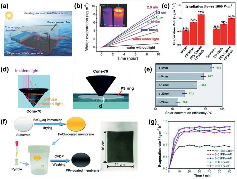
a) Schematic illustrating point‐of‐use devices for direct and all‐in‐one solar distillation for fresh water production.[ 38 ] b) Time course of the water evaporation performance under various conditions.[ 38 ] Pink, green, purple, and brown lines: water with floating SS meshes of different PPy coating thicknesses. Inset: An IR camera image of water beakers with light irradiation for 2 h. Left beaker: water only. Right beaker: water with the floating PPy‐coated mesh on the surface. c) νw and ηSTE under different conditions.[ 99 ] d) Schematic illustrating the simplified reflection processes of a 3D cone with an apex angle of 70° and the location of the cone by a PS ring with different hole diameters.[ 121 ] e) ηSTE of cone‐70 with different hole diameters. f) Schematic illustration of a PPy‐coated air‐laid paper prepared using the CVD method, and g) the corresponding time course of the water evaporation rates of the samples.[ 122 ] a,b) Reproduced with permission.[ 38 ] Copyright 2015, Wiley‐VCH. c) Reproduced with permission.[ 99 ] Copyright 2017, The Royal Society of Chemistry. d,e) Reproduced with permission.[ 121 ] Copyright 2018, The Royal Society of Chemistry. f,g) Reproduced with permission.[ 122 ] Copyright 2018, Wiley‐VCH.
Subsequently, an 80 nm‐thick PPy film coated polyvinylidene fluoride (PVDF) membrane was prepared using the chemical vapor deposition (CVD) method on an ammonium persulfate‐treated membrane (Figure 12d,e).[ 121 ] Notably, this dark membrane was folded into a 3D cone to produce increased solar light absorption from the multiple reflections inside the cone with a suitable apex angle. The optimized cone with an apex angle of 70° exhibited a high νw of 1.70 kg m−2 h−1 from a ΔT PT of 53 K and an efficient ηSTE of 93.8%. Recently, a PPy‐coated air‐laid paper was prepared using the CVD method (Figure 12f,g).[ 122 ] The ηSTE was 81.9% with a high ΔT PT of 57.3 K, affording a νw of 1.41 kg m−2 h−1.
Since the IDI‐PES film on a PET film shows a high ΔT PT within 5 s, the film containing 16.7 wt% IDI was explored for the evaporation of water with an NIR laser (Figure 13a–c).[ 54 ] The temperature of the water droplet increased to 40 °C upon NIR exposure (1064 nm, 0.58 W cm−2) and it was completely evaporated from the exposed area, leaving a zero mass within 7.5 min. Furthermore, selective exposure was ensured by the waveguiding optic system to evaporate the water droplets only onto the target area from a wide range of drops. Based on the linear correlation of the droplet weight over time, νw was determined to be 3.65 kg m−2 h−1, which is much higher than the typical solar νw (0.08–1.4 kg m−2 h−1 under AM 1.5 irradiation). The Q e and ηw values of the PT heater were 0.2 W cm−2 and 68.8%, respectively. These results might originate from the high transparency of the film and the low heat loss from the polymeric binder and substrate, which might contribute to such a high νw and ηw . Notably, a droplet of saturated brine was selectively evaporated upon exposure to an NIR laser (1064 nm, 0.76 W cm−2) within 4 min, leaving dried NaCl salt on the surface (Figure 13d).
Figure 13.
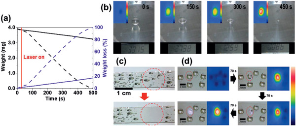
a) The weight (black) and the %wt loss (blue) of a water droplet over time for NIR‐irradiated (dashed) and nonirradiated (solid) samples in air.[ 54 ] b) Photo images of the mass change of a water droplet over time upon exposure to 1064 nm laser. Inset: IR camera images of the IDI‐PES surface with a temperature range of 20–60 °C. c) Evaporation of water droplets with large areas. d) Selective evaporation of a brine droplet and the corresponding IR camera images. a–d) Reproduced with permission.[ 54 ] Copyright 2020, Wiley‐VCH.
4.2. Photothermal Actuators
As described above, the temperature induced by the PT effect of organic materials even reached to >100 °C. This high temperature can induce a spatiotemporal thermal change in the contacting thermally responsive layer of the PT layer, such as a glass transition, volume expansion, melting, degradation, etc., depending on the ΔT PT.[ 9 ] Such changes could generate bending and movement of the PT actuators, allowing a remote controlled wireless actuation. Several types of thermally responsive layers are possible: 1) an elastomer with high coefficient of thermal expansion (CTE), 2) liquid crystal (LC)‐doped polymer composite or LC polymers (LCPs), and 3) humidity‐responsive layer, depending on the driving mechanism of the actuator (Figure 10d). In the PT film with a large CTE elastomer layer (C‐type), the bilayer is bent toward the direction of elastomer because it is more expandable than the PT film. Similarly, the bilayer containing LC polymers (L‐type) is bent toward the direction of the LC layer. The bilayer with the humidity‐responsive layer (H‐type) is bent toward the direction of the PT film because it shrinks through the loss of water molecules inside PT layer following PT heating. The bending angle (θb) (Figure 14a) is linearly proportional to ΔT PT.
| (20) |
| (21) |
where L is the length of the actuator, α is the CTE, E is Young's modulus, and l is the thickness, with the subscripts PT and TR denoting the PT heating film and thermally responsive layer, respectively.
Figure 14.
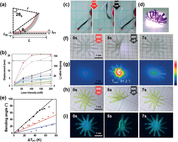
C‐type actuators. a) Modeling for actuation of the bimorph. b) PT displacement (solid, line) and θb (empty, dashed line) of PEDOT/PDMS bimorphs upon exposure to different laser intensities with different thicknesses of the bimorph.[ 29 ] c) Reversible folding of PEDOT/PDMS upon exposure to an NIR laser. d) A photo image of a venus flytrap upon exposure to an NIR laser. e) θb (dot) of IDI‐PES/PDMS bimorphs with ΔT PT.[ 54 ] f) Photo images and g) IR camera images of the folding and unfolding of IDI‐PES/PDMS induced by tuning NIR irradiation on and off, respectively. h) Photo images of a yellow flytrap under room light and i) a luminescent flytrap from IDI‐PES/PDMS under UV light by NIR switching. a,e–i) Reproduced with permission.[ 54 ] Copyright 2020, Wiley‐VCH. b–d) Reproduced under the terms of a CC‐BY license.[ 29 ] Copyright 2019, The Authors. Published by Springer Nature.
As an example of the C‐type actuator, a bimorph consisting of a PEDOT film on a PDMS layer was reported (Figure 14b–d).[ 29 ] The thicknesses of the two layers were optimized by considering Young's modulus of the two layers to maximize the k value. The bilayer with 0.4 and 70 µm‐thick for PEDOT and PDMS, respectively, showed reversible and fast bending within 2 s, a θb >120, and a displacement of 20 mm upon NIR exposure (198 mW) due to a high ΔT PT of 106 K. Since most actuators, regardless of their working mechanism, are deeply colored or turbid, actuators with full color or transparency are rare. However, the NIR‐II absorptive IDI allowed the realization of a transparent PT actuator due to its high transparency (93%) (Figure 4g).[ 54 ] The IDI‐PES coated PDMS bimorph generated a ΔT PT of 98 K and showed a large reversible θb (>70°) upon exposure to a 1064 nm laser (0.71 W cm−2) (Figure 14e). The blocking force of this actuator was determined to be 2.6 GPa, which may be useful for creating a transparent artificial muscle. Notably, by taking advantage of the high transparency of IDI‐PES, the composite film produced an actuator with a vivid color and an emissive actuator upon the addition of dyes and fluorophores (Figure 14f–i). For example, the IDI‐PES/PDMS bilayer showed blue‐green fluorescence after mixing with Coumarin 153, achieving a yellow‐colored and luminescent actuator. Furthermore, the bilayer was stable in water and exhibited free movement on water.
Regarding the H‐type actuator, the PT layer consists of polymer and carbon materials, such as graphene oxides (GOs), to improve actuation helped by high humidity responsive properties. The grafting of P3HT onto the surfaces of the RGO composite was reported for the PT layer (Figure 15a).[ 128 ] A high ηPT of 82% was achieved from this composite upon exposure to a 532 nm laser, which exhibited a photoswitchable bimetallic strip as a switch for an LED bulb (Figure 15b). In another case, the PDA‐modified RGO composite (humidity‐responsive layer) onto the NOA‐63 layer was applied as a bilayer PT actuator (Figure 15c).[ 129 ] The hydrophilic composite layer absorbed moisture leading to swelling (flat) and loss of water occurred following PT heating, which led to shrinking (bending), with a reversible θb of 80° (Figure 15d,e). Subsequently, the humidity‐responsive GO‐PDA composite on the RGO layer was used as a light‐driven actuator,[ 130 ] which showed reversible folding within 3 s and a θb ≈180° with a ΔT PT of 32 K. Notably, it was applied to a wormlike walking device based on all‐graphene self‐folding paper (Figure 15f). Compared to the inorganic materials reported for the PT heating layer, such as MoS2 and MXene, organic material‐based composite films exhibit a high ηPT and high ΔT PT, as well as flexibility.
Figure 15.
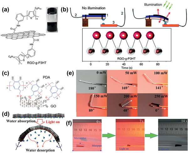
H‐type actuators. a) Molecular structures of RGO‐g‐P3HT.[ 128 ] b) Schematic illustrating the working principle of a bimetallic switch. On/off state of an LED bulb controlled by using the bimetallic switch. c) Molecular structures of GO‐PDA.[ 130 ] d) Schematic illustrating the working principle of the GO‐PDA composite on RGO layer. e) Dependence of θb on illumination intensity. f) Photo images of the wormlike walking device upon exposure to light. a,b) Reproduced with permission.[ 128 ] Copyright 2014, The Royal Society of Chemistry. c–f) Reproduced with permission.[ 130 ] Copyright 2015, The Authors. Published by AAAS.
Regarding the L‐type actuator, PANI with LC elastomer composites was prepared by uniaxially stretching a pre‐cross‐linked composite following a complete cross‐linking reaction.[ 36 ] The composite of 1 wt% PANI (ES) showed a reversible NIR‐triggered photoactuation and heavy‐lift capability (11.3 g) upon exposure to an 808 nm laser that generated a ΔT PT of 112 K. Later, PDA NP‐doped LC elastomer composites were synthesized by transesterification[ 131 ] This transesterification of the composite was further triggered by a high I pd (1.4 W cm−2) to bend at 160 °C and hold a 3D shape after heating to 200 °C. Recently, PDA‐coated LC elastomers were applied as light‐driven artificial muscles.[ 132 ] These elastomers showed fast lifting‐recovering cycles within 0.65 s and afforded a prototype robotic swimmer that was able to move on a water surface by reversible bending and unbending motions induced by NIR light.
PT heating can be coupled with other types of actuation mechanisms such as photochemical reactions and molecular motion by photoisomerization. For example, a shape programming and shape morphing actuator was prepared using an azobenzene‐based photoactive LC composite (Figure 16 ).[ 133 ] The azobenzene unit undergoes trans‐to‐cis photoisomerization by UV light to control the cis content (Figure 16d). The PT heating led to the LC unit transforming in shape under UV light, and cis‐to‐trans photoisomerization was controlled by blue light exposure to switch the actuator to its initial state (Figure 16e,f). Subsequently the LC actuator was reconfigured with UV light followed by red light illumination to adapt to other shapes (Figure 16g). A UV light fuel gripper was demonstrated as a microrobot that lifts an object (Figure 16h,i). The actuating parameters of some representative PT actuators are summarized in Table 1.
Figure 16.
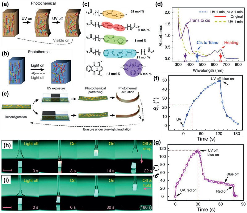
L‐type actuators. Schematic illustrating a) photochemical and b) PT actuation.[ 133 ] c) Chemical composition of the LC monomer mixture. d) Absorption spectra of the LC film. e) θb change upon different stimuli. f) Photochemically induced bending upon subsequent UV and blue light excitation. g) Synergistic actuation under simultaneous UV and red light illumination. An object being lifted up in (h,i) weighs 12 mg. Scale bars: 5 mm. Reproduced under the terms of a CC‐BY license.[ 133 ] Copyright 2018, The Authors. Published by Springer Nature.
4.3. p‐PTM films for Cell Sheet Harvesting
As the temperature of the PT layer can be precisely controlled, for example, by varying the I pd and thickness of the PT layer, the PT effect has been applied to cell engineering,[ 134 , 135 ] including the ablation of unwanted cells such as cancer cells while harvesting wanted cells without heat damage.[ 27 ] Live cell sheet harvesting in spatiotemporal tissue engineering provides the reproduction and replacement of nonfunctional tissues and organs.[ 89 , 135 ] Thus, several methods have been investigated using thermo‐, photothermo‐, electro‐ and photochemical stimuli, or a combination of these stimuli, to harvest live cells and cell sheets by inducing the cells to detach from a substrate due to a change (hydrophilicity, morphology, solubility, surface potential, etc.) in the substrate surface.[ 136 ]
Noninvasive and selective harvesting of stem cells was reported with a PEDOT film exposed to an NIR laser.[ 27 ] By controlling the doping level of the PEDOT film, cell viability at the PEDOT surface and the ΔT PT of the laser‐exposed area were optimized to proliferate mesenchymal stem cells (MSCs) onto the PEDOT surface and harvest the MSCs via PT heating, respectively. To harvest cell sheets that maintain cell–cell interactions, PT disassembly of triple helix collagen was used. Thus, the collagen layer was coated on a PEDOT surface, and human dermal fibroblast (HDF) cells proliferated on top of the collagen layer to form a cell sheet. The stable triple‐helical conformation of collagen under cell culture conditions (≈37 °C) (Figure 17a) unfolded upon PT heating (≈41 °C) due to exposure to an NIR laser, liberating individual strands of collagen into an aqueous medium and attenuating HDF cell–surface interaction. Simultaneously, the HDF cell sheet is harvested while floating in the medium.[ 10 ] Using this highly effective photodetachment method and optical system, live cell sheets were harvested within a short exposure time (5 min) to an 808 nm laser (2.5 W cm−2). Notably, the efficiency of cell detachment (ηd), which is determined from the ratio of the detached cell area over the NIR‐exposed area, was determined to be 168% at 2.5 W cm−2, indicating that the area of detached cells is larger than the NIR‐exposed area (Figure 17b,c). Taking advantage of the harvesting of cell sheets with precisely controlled light, multiple human adipose‐derived stem cell (ADSC) sheets with tailored shapes were harvested from the collagen coated PEDOT film using a patterned PDMS lens for NIR diffraction (Figure 17d–f), to afford a cell sheet with a large area of 19 cm2 (3 cell sheets) after one exposure to an 808 nm laser (Figure 17g–i).[ 137 ]
Figure 17.
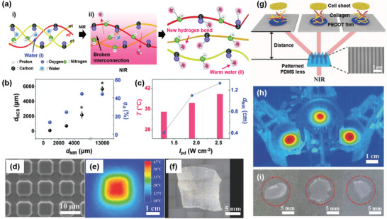
a) Schematic structure of collagens having one α2 and two α1 polypeptide chains i) in the unexposed region and dissociated, unfolded collagens ii) in the NIR‐exposed region.[ 10 ] The water molecules (I) in the triple helical structure are expelled upon PT heating to generate single helical collagens that form new hydrogen‐bonding interactions with warm water molecules (II) and then dissociate into cell media. b) Effect of the diameter of the NIR‐exposed area (d NIR) on the diameter of the harvested cell sheet (d HCS, black) and ηd (blue). c) Effect of the I pd value (black) on the temperature increase at the PEDOT surface (red) and on the d NIR (blue). d) FESEM image of a square patterned PDMS lens.[ 137 ] e) Corresponding IR camera image obtained for the PT pattern on the PEDOT substrate. f) Corresponding microscopic image of the harvested HDF cell sheet. g) Schematic illustrating the harvesting of multiple cell sheets with a line patterned PDMS lens. Inset: An FESEM image of the line patterned PDMS lens. h) Corresponding IR camera image of three PT patterns. i) Photo images of the harvested human ADSC sheet. a–c) Reproduced with permission.[ 10 ] Copyright 2015, Wiley‐VCH. d–i) Reproduced with permission.[ 137 ] Copyright 2017, Wiley‐VCH.
Recently, PDA NP and poly(N‐isopropylacrylamide) (PNIPAM) hydrogel composites have been used for single cell release from the composite surface, which were used as a p‐PTM and thermally responsive polymer, respectively.[ 138 ] After exposure to an 808 nm laser for 1 min (10 W cm−2), the hydrogel released 50% of the seeded cells. The composite layer was photocontrolled from hydrophilic to hydrophobic properties above the lower critical solution temperature, causing a reduction in the volume to release cells from the surface. Finally, these PT cell sheet harvesting results have been incorporated in various studies examining intercellular interactions, artificial tissue engineering, skin reproduction, and organ regeneration.[ 135 ]
4.4. Photothermal Energy Harvesting
PT conversions are accompanied by carrier generation and transport to perform PTEs,[ 26 , 30 , 139 , 140 , 141 , 142 ] photothermovoltaics,[ 28 , 143 , 144 ] and PT mechanical energy conversions[ 123 , 145 ] integrated with PVs, Peltier modules, piezoelectrics, and Stirling engines. For the efficient conversion of light to thermal energy for useful electric or mechanical energies, a high ηPT of the PT film is crucial for energy conversion. The PTE effect consists of two processes: 1) the absorbed light energy is converted into thermal energy, and 2) it spatiotemporally triggers the carriers to move toward the cold part which generates electricity by the thermoelectric phenomenon.[ 11 , 26 ] The output power and PTE efficiency (ηPTE) can be determined from the following equations:
| (22) |
| (23) |
| (24) |
| (25) |
| (26) |
where PF is the power factor, S is the Seebeck coefficient, V PTE is the output voltage, ∇T x is the temperature gradient, I is the output current, R is the resistance between the two electrodes, and P is the output power. Therefore, the PTE mechanism (mostly from a single layer) is unlike that in from PVs (multilayers), for which semiconductors are used to convert light into electricity due to the separation of electrons and holes.
Among the p‐PTMs, the PTE effect was first reported with a PEDOS‐C6 film where the Au electrode was used to collect electricity (Figure 18a).[ 26 ] This PTE film affords a V PTE of 900 µV and a PFPTE of 354.7 µW m−1 K−2 upon exposure to an 808 nm laser, with stability over 1000 cycles (Figure 18b). It was applied as a body heat generator by touching it to a person's arm (Figure 18c). Later, the PEDOT film with an optimized degree of crystallinity was recently applied to a PTE device to yield a PFPTE of 620 µW m−1 K−2, which was 1.7 times higher than the PEDOT‐C6 film described above.[ 30 ] This substantial increase in PFPTE might be ascribed to the increased σe and DOS in the PEDOT film, according to Equation (15). A solar heat harvester was prepared from a 2.23 mm‐thick PEDOT film, which was connected to other 3 PEDOT film devices in parallel (Figure 18d). Upon exposure to solar light, this harvester showed a high I pd of 38 m W m−2 in an absorber‐free system (Figure 18e). This harvester also showed a high energy density of 420 Wh g−1 compared to the other absorber‐free inorganic solar thermoelectric systems.[ 141 ]
Figure 18.
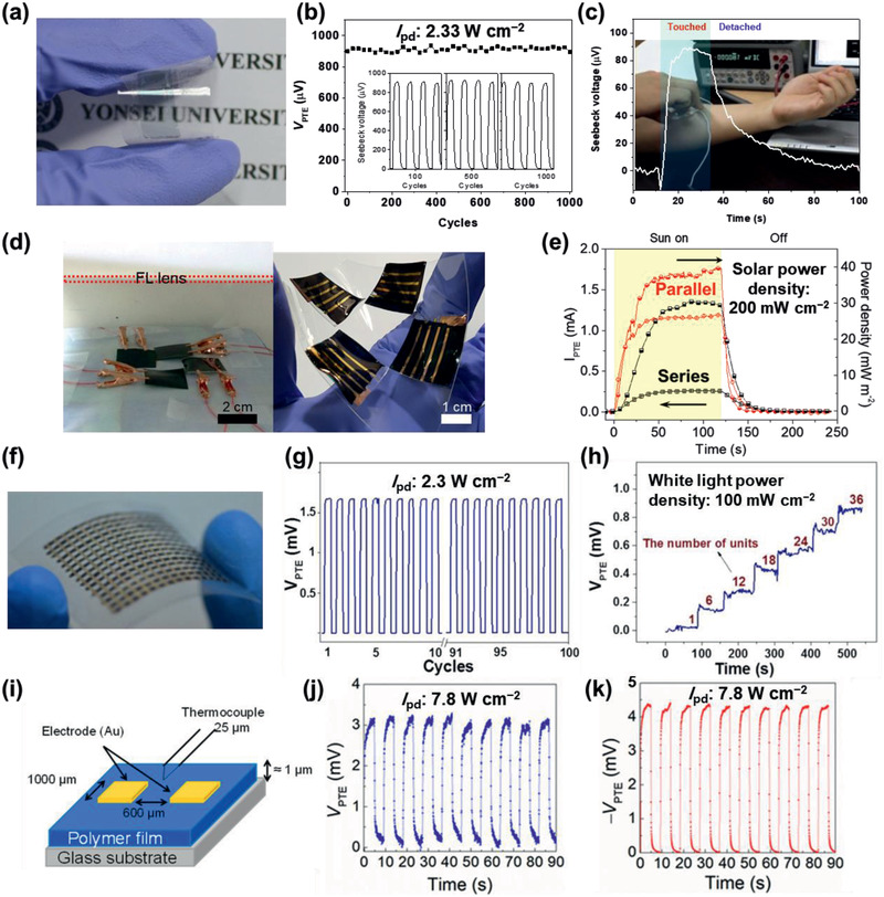
PTE devices. a) A photo image of the doped PEDOS‐C6 film.[ 26 ] b) The cyclability of S PTE generation upon exposure to an 808 nm laser over 1000 cycles. c) Seebeck voltage generation of the harvester due to touching on a person's arm. d) Photo images of the film connection using a solar simulator and the flexible PTE solar harvester.[ 30 ] e) I PTE (empty symbol) and power density (half‐filled symbol) connected in series (black) and parallel (red). f) A photo image of NIR detectors on a PET substrate.[ 146 ] g) NIR detection cyclability of the PTE device for 100 cycles. h) V PTE generation when varied units. i) An illustration of the PTE device configuration.[ 147 ] Cyclability of V PTE of j) PTII and k) TzQI‐TDPP films. a–c) Reproduced with permission.[ 26 ] Copyright 2013, Wiley‐VCH. d,e) Reproduced with permission.[ 30 ] Copyright 2019, The Royal Society of Chemistry. f–h) Reproduced with permission.[ 146 ] Copyright 2015, American Chemical Society. i–k) Reproduced with permission.[ 147 ] Copyright 2019, American Chemical Society.
A Cu‐based organic complex polymer, poly[Cux(Cu‐ett)], mixed with PDVF as a polymeric thermoelectric composite was applied as the NIR detection film (Figure 18f).[ 146 ] The single and 36‐leg integrated device showed V PTE of 25 µV and 0.9 mV, respectively, upon exposure to solar light, along with a S PTE of 79 µV K−1 (Figure 18g,h). Recently, poly(thienoisoindigo) (PTII) and poly(thiadiazoloquinoxalinimide‐thiophene‐flanked diketopyrrolopyrrole) (TzQI‐TDPP) polymers showed a high absorption in the NIR‐II region as p‐ and n‐type PTE films, respectively (Figure 18i–k), with a λmax of 1295 and 1591 nm, respectively.[ 147 ] Notably, the TzQI‐TDPP film showed a high V PTE of −5.3 mV and S PTE of −306 µV K–1 upon irradiation with a 1700 nm laser (7.8 W cm–2). However, this film showed a low PFPTE of 0.013 µW m–1 K–2 because of its low σe (2.2 × 10⁻² S cm–1).
Other types of PT energy‐harvesting devices are possible, such as PT pyroelectric and piezoelectric devices. Furthermore, these devices can be integrated as a thin film to obtain a hybrid energy harvester that harvests multiple sources of energy. For example, the PEDOT film was coated onto a pyroelectric PVDF film and a Peltier module. Then, these units were integrated with dye‐sensitized solar cells (DSSCs) (Figure 19a).[ 28 ] The DSSCs absorbed visible light to generate PV energy, and the NIR light passing through the DSSCs was absorbed by the PEDOT film at the bottom, which heated the poly(vinylidene fluoride‐co‐trifluoroethylene) film to generate both piezoelectric energy and PT heat energy upon irradiation with solar light (Figure 19b). Finally, the heat generated by the PEDOT film drove the Peltier module, and all the electric energy was accumulated in a capacitor to operate the electrochromic device (Figure 19c,d). The hybrid harvester exhibited a high solar energy conversion efficiency of 11.7%, which was 20% higher than that obtained for the DSSC alone. Notably, an LED lamp and electrochromic display were operated by the solar light harvesting device.
Figure 19.
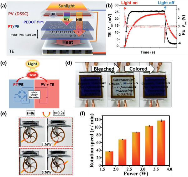
Hybrid energy harvesting systems. a) Illustration of photovoltaic and PT pyro‐thermoelectric devices.[ 28 ] b) Thermoelectric (filled) and piezoelectric (open) output voltage of under sunlight on/off conditions without (black square) and with a PV (red circle). c) Circuit diagram of the PT hybrid energy harvester. d) Switching of an electrochromic device using the hybrid energy harvesting system. e) Photo images of a rotation of a Stirling engine.[ 111 ] f) Rotation speed statistics of the Stirling engine upon exposure to different laser powers. a–d) Reproduced with permission.[ 28 ] Copyright 2015, American Chemical Society. e,f) Reproduced with permission.[ 111 ] Copyright 2017, American Chemical Society.
A D–A type PT polymer, TBDOPV‐DT was reported along with its PT–electric and PT–mechanical converters.[ 111 ] A high level of absorption in the NIR‐II region was observed for the TBDOPV‐DT film, with a ηPT of 50.5%. A high Seebeck voltage of 29.7 mV was obtained from the hybrid PT film and Peltier module put under a piece of pig skin using a 1064 nm laser (0.82 W). Additionally, the hybrid PT film and Stirling engine displayed a light–mechanical energy conversion efficiency of 0.0054% at a light power of 1.76 W (Figure 19e,f).
5. Summary and Future Outlook
Conjugated organic PTMs have been extensively examined over the last decade due to their unique tunability of heat generated from light, high level of light absorption, ease of synthesis and modification of molecular structures, and low cytotoxicity in various applications. The chemical structures of the organic PTMs have been designed to retain a long conjugated group and a D−A structure, to introduce ICT resulting in a redshift in the absorption toward the NIR region and an increased extinction coefficient. The representative m‐PTMs are ICG, IR‐X, Croc, DPP, and IDI, which show strong NIR‐I absorption to provide maximum ηPT values of 9%, 20%, 60%, 71%, and 75%, respectively, in the NP or in polymeric media. On the other hand, a thin film of p‐PTMs has been produced without binder through a simple process such as SCP or CVD methods in that monomers are directly polymerized on a substrate. The representative PEDOT film prepared by SCP method showed a maximum ηPT of 93% and the PPy‐coated air‐laid paper prepared by CVD method showed ηPTW of 81.9%.
Starting from an ηPT of 13% for the PProDOS film reported in 2011, the ηPT values for p‐PTMs reached ≈93% by 2019, with maximum ηPT values of 93%, 42%, 35%, 65%, 71%, and 66% reported for PEDOT, PEDOS, PANI, PPy, PDDP, and D‐A polymers, respectively, which show generally higher ηPT values than m‐PTMs. The μ and ΔT PT are linearly correlated with the ηPT, which conveniently provides the design and programming of thermal engineering with PTMs. While some inorganic composites, such as MXene@PDA‐PU composites, show high ΔT PT in the visible region, p‐PTMs such as PEDOTs show a high ΔT PT in the NIR region. Furthermore, the light sensitivity of organic PTMs is shifted to the NIR‐I and even NIR‐II regions, as observed for PEDOTs, TBDOPV‐DT, and IDI, reaching >140 K upon excitation with a 1064 nm laser. This redshift for light excitation might reduce unwanted side reactions during PT applications.
As summarized in Table 1 for representative examples, organic PTMs possess great potential in the development of PTW, PTA, PTE, and PTCH. The outcome and efficiency of each application are quite promising and some of them show potential for multiple applications. For example, the transparent IDI exhibited a high ΔT PT, leading to effective water evaporation with a maximum νw of 1.70 kg m−2 h−1 and transparent actuators which provides new possibilities for colorful actuators. The PEDOT films showed not only a high ΔT PT but also a high Seebeck effect, to exploit the film for PTA with a high θb of 150°, PTE with a PFPTE of 690 µW m−1 K−2, and PTCH with a fast live cell sheet harvesting capacity. Transparency of some organic PTMs is an exceptional characteristic which promote multifarious properties such as integrating ability with piezoelectric, pyroelectric, and solar light harvesting devices. The transparency can be controlled by film thickness, ordering of molecules or polymers, porosity, and PTM content in binder.
The PT effect in a film represents a convenient tool for maneuvering heat and can take advantage of light stimuli such as a high degree of spatiotemporal control by the wavelength, intensity, diffraction, and polarization of light. Therefore, the applications have been extended to various fields, not only those areas that have been developed for inorganic PTMs but also new areas, where spatiotemporal thermal engineering is required. [ 113 , 148 , 149 , 152 , 153 ]
In addition, the strong PT effect and compatibility with mechanically synergistic polymers or inorganic PTMs based on CPs afford composite films which increase the application potential due to the enhanced ηPT. For example, a catechol‐conjugated poly(vinylpyrrolidone) sulfobetaine (PVPS):PANI film was reported for PT killing of bacteria.[ 150 ] Another example is a PT cloth weaved from an elastic PU tube coated with PPy that showed a ΔT PT of 50 K and ηPT of 73.9% under solar light irradiation, [ 148 ] which is comparable to that obtained for MXene@PDA‐integrated PU composites.[ 149 ] In addition, a self‐healing PT composite with a boron nitrogen nanosheet (f‐BNNS)/PEDOT:PSS/PNIPAM hydrogel film exhibited a ΔT PT of 59 K upon exposure to an 808 nm laser (1.01 W), affording an on‐skin motion sensor and heating patch.[ 152 ] Compared to inorganic‐based composites, such as AgNP@MXene‐PU,[ 151 ] CP‐based composite films have been reported to be a high priority for PT engineering because of their high ηPT and large stretchability for various applications.
Various PT films with noteworthy organic PTMs are now available; however, understanding the PT effect and the applications of these films has only just begun. Thus, it is expected that organic PTMs will shed light on a better understanding of the PT effect and provide a guide for the rational design of the target device for more precise and effective spatiotemporal thermal engineering. For future development of PTMs, several strategies can be conducted as follows. The rational design for efficient m‐PTMs should achieve a band gap tuning through intramolecular D–A structure to extend π‐conjugation. For the efficient p‐PTM design, a low band gap structure could be designed with extension of π‐conjugation in the main chain units for a high molar extinction coefficient in the NIR range. Further consideration on the degree of crystallinity and carrier mobility induced by the DOS broadening at E F is important to enhance nonradiative relaxation. A method of adjusting the band structure using a dopant, which has been actively studied recently, can also be a good challenge for p‐PTMs. Since only recently it has been reported that ηPT and μ are related to each other in PEDOT films, it is necessary to explore the versatility of various CPs in the future for both theoretical and experimental perspectives, to develop a guiding principles to the PT properties of organic PTMs. As the PT effect in the PTM films provide precise spatiotemporal thermal engineering, the application of these organic PTMs could be extended in various fields including the emerging applications in invisible target PT imaging and therapies, molecular motion controls, artificial neural network, and flexible energy conversion devices.
Conflict of Interest
The authors declare no conflict of interest.
Supporting information
Supporting Information
Acknowledgements
H.K. and B.K. contributed equally to this work. This review was supported by a National Research Foundation (NRF) grant funded by the Korean government (Ministry of Science, ICT & Future Planning, MSIP) through the Global Research Lab (GRL: 2016K1A1A2912753) and Creative Materials Discovery Program (2018M3D1A1058536), BK21 plus program in 2020 (2018H1D3A2001751), and AOARD, Air Force Office of Scientific Research (AFOSR) under the grant number FA9550‐19‐S‐0003.
Biographies
Hee Jung Kim is a Ph.D. student in the Department of Chemical and Biomolecular Engineering at Yonsei University. She received her B.S. degree in polymer science and engineering from Pusan National University and M.S. degree in chemical and biological engineering from Korea University. Her research interests are conjugated materials for photothermal applications and factors affecting photothermal properties.

Byeonggwan Kim is a research scientist in the Department of Chemical and Biomolecular Engineering at Yonsei University. He received his B.S. and Ph.D. degrees under the supervision of Prof. Eunkyoung Kim in chemical and biomolecular engineering from Yonsei University. He worked as a postdoctoral researcher at the French National Center for Scientific Research (CNRS). His research interests include the development of novel conjugated materials for photothermal and thermoelectric energy harvesting and storage devices.

Eunkyoung Kim is a professor in the Department of Chemical and Biomolecular Engineering at Yonsei University. She received her B.S. degree in chemistry from Yonsei University, an M.S. degree from Seoul National University (Seoul Korea), and a Ph.D. degree from the University of Houston, USA. Her main research interest is the development of novel methods for controlling the structure and functionality of conjugated materials for electrochromics, thermoelectrics, and photothermal switching devices.

Kim H. J., Kim B., Auh Y., Kim E., Conjugated Organic Photothermal Films for Spatiotemporal Thermal Engineering. Adv. Mater. 2021, 33, 2005940. 10.1002/adma.202005940
References
- 1. Qin Z., Bischof J. C., Chem. Soc. Rev. 2012, 41, 1191. [DOI] [PubMed] [Google Scholar]
- 2. Lim E.‐K., Kim T., Paik S., Haam S., Huh Y.‐M., Lee K., Chem. Rev. 2015, 115, 327. [DOI] [PubMed] [Google Scholar]
- 3. Yang X., Yang M., Pang B., Vara M., Xia Y., Chem. Rev. 2015, 115, 10410. [DOI] [PubMed] [Google Scholar]
- 4. Shi Y., Liu M., Deng F., Zeng G., Wan Q., Zhang X., Wei Y., J. Mater. Chem. B 2017, 5, 194. [DOI] [PubMed] [Google Scholar]
- 5. Li J., Pu K., Chem. Soc. Rev. 2019, 48, 38. [DOI] [PubMed] [Google Scholar]
- 6. Liu Y., Bhattarai P., Dai Z., Chen X., Chem. Soc. Rev. 2019, 48, 2053. [DOI] [PMC free article] [PubMed] [Google Scholar]
- 7. Gao M., Zhu L., Peh C. K., Ho G. W., Energy Environ. Sci. 2019, 12, 841. [Google Scholar]
- 8. Zhang C., Liang H.‐Q., Xu Z.‐K., Wang Z., Adv. Sci. 2019, 6, 1900883. [DOI] [PMC free article] [PubMed] [Google Scholar]
- 9. Han B., Zhang Y.‐L., Chen Q.‐D., Sun H.‐B., Adv. Funct. Mater. 2018, 28, 1802235. [Google Scholar]
- 10. Kim J. D., Heo J. S., Park T., Park C., Kim H. O., Kim E., Angew. Chem., Int. Ed. 2015, 54, 5869. [DOI] [PubMed] [Google Scholar]
- 11. Lu X., Sun L., Jiang P., Bao X., Adv. Mater. 2019, 31, 1902044. [DOI] [PubMed] [Google Scholar]
- 12. Razeghi M., Fundamentals of Solid State Engineering, 3rd ed., Springer, Berlin: 2019. [Google Scholar]
- 13. DuBois D. F., Ann. Phys. 1959, 7, 174. [Google Scholar]
- 14. Jauffred L., Samadi A., Klingberg H., Bendix P. M., Oddershede L. B., Chem. Rev. 2019, 119, 8087. [DOI] [PubMed] [Google Scholar]
- 15. Webb J. A., Bardhan R., Nanoscale 2014, 6, 2502. [DOI] [PubMed] [Google Scholar]
- 16. Ali M. R. K., Wu Y., El‐Sayed M. A., J. Phys. Chem. C 2019, 123, 15375. [Google Scholar]
- 17. Huang X., Jain P. K., El‐Sayed I. H., El‐Sayed M. A., Lasers Med. Sci. 2007, 23, 217. [DOI] [PubMed] [Google Scholar]
- 18. Gharatape A., Davaran S., Salehi R., Hamishehkar H., RSC Adv. 2016, 6, 111482. [Google Scholar]
- 19. Kelly K. L., Coronado E., Zhao L. L., Schatz G. C., J. Phys. Chem. B 2003, 107, 668. [Google Scholar]
- 20. Qin Z., Wang Y., Randrianalisoa J., Raeesi V., Chan W. C. W., Lipiński W., Bischof J. C., Sci. Rep. 2016, 6, 29836. [DOI] [PMC free article] [PubMed] [Google Scholar]
- 21. Jiang Y., Zhao X., Huang J., Li J., Upputuri P. K., Sun H., Han X., Pramanik M., Miao Y., Duan H., Pu K., Zhang R., Nat. Commun. 2020, 11, 1857. [DOI] [PMC free article] [PubMed] [Google Scholar]
- 22. Shi C., Wu J., Pan D., J. Biomed. Opt. 2016, 21, 050901. [DOI] [PubMed] [Google Scholar]
- 23. Zhu H., Cheng P., Chen P., Pu K., Biomater. Sci. 2018, 6, 746. [DOI] [PubMed] [Google Scholar]
- 24. Huang J. X., Kaner R. B., Nat. Mater. 2004, 3, 783. [DOI] [PubMed] [Google Scholar]
- 25. Kim B., Kim J., Kim E., Macromolecules 2011, 44, 8791. [Google Scholar]
- 26. Kim B., Shin H., Park T., Lim H., Kim E., Adv. Mater. 2013, 25, 5483. [DOI] [PubMed] [Google Scholar]
- 27. You J., Heo J. S., Kim J., Park T., Kim B., Kim H.‐S., Choi Y., Kim H. O., Kim E., ACS Nano 2013, 7, 4119. [DOI] [PubMed] [Google Scholar]
- 28. Park T., Na J., Kim B., Kim Y., Shin H., Kim E., ACS Nano 2015, 9, 11830. [DOI] [PubMed] [Google Scholar]
- 29. Lim H., Park T., Na J., Park C., Kim B., Kim E., NPG Asia Mater 2017, 9, e399. [Google Scholar]
- 30. Kim B., Han M., Kim E., J. Mater. Chem. A 2019, 7, 2066. [Google Scholar]
- 31. Wang H., Chu W., Chen G., Adv. Electron. Mater. 2019, 5, 1900167. [Google Scholar]
- 32. Ng K. K., Zheng G., Chem. Rev. 2015, 115, 11012. [DOI] [PubMed] [Google Scholar]
- 33. Kim J., Lee E., Hong Y., Kim B., Ku M., Heo D., Choi J., Na J., You J., Haam S., Huh Y. M., Suh J. S., Kim E., Yang J., Adv. Funct. Mater. 2015, 25, 2260. [Google Scholar]
- 34. Kim B., Hwang J. U., Kim E., Energy Environ. Sci. 2020, 13, 859. [Google Scholar]
- 35. Yang J., Choi J., Bang D., Kim E., Lim E. K., Park H., Suh J. S., Lee K., Yoo K. H., Kim E. K., Huh Y. M., Haam S., Angew. Chem., Int. Ed. 2011, 50, 441. [DOI] [PubMed] [Google Scholar]
- 36. Liu W., Guo L.‐X., Lin B.‐P., Zhang X.‐Q., Sun Y., Yang H., Macromolecules 2016, 49, 4023. [Google Scholar]
- 37. Yang K., Xu H., Cheng L., Sun C. Y., Wang J., Liu Z., Adv. Mater. 2012, 24, 5586. [DOI] [PubMed] [Google Scholar]
- 38. Zhang L., Tang B., Wu J., Li R., Wang P., Adv. Mater. 2015, 27, 4889. [DOI] [PubMed] [Google Scholar]
- 39. Zha Z., Yue X., Ren Q., Dai Z., Adv. Mater. 2013, 25, 777. [DOI] [PubMed] [Google Scholar]
- 40. Kim M., Lee J.‐H., Nam J.‐M., Ad. Sci. 2019, 6, 1900471. [DOI] [PMC free article] [PubMed] [Google Scholar]
- 41. Xu J.‐W., Yao K., Xu Z.‐K., Nanoscale 2019, 11, 8680. [DOI] [PubMed] [Google Scholar]
- 42. Dong L., Zhao Y., Mater. Chem. Front. 2018, 2, 1932. [Google Scholar]
- 43. Wang D., Lee M. M. S., Xu W., Shan G., Zheng X., Kwok R. T. K., Lam J. W. Y., Hu X., Tang B. Z., Angew. Chem., Int. Ed. 2019, 58, 5628. [DOI] [PubMed] [Google Scholar]
- 44. Zhao Z., Chen C., Wu W., Wang F., Du L., Zhang X., Xiong Y., He X., Cai Y., Kwok R. T. K., Lam J. W. Y., Gao X., Sun P., Phillips D. L., Ding D., Tang B. Z., Nat. Commun. 2019, 10, 768. [DOI] [PMC free article] [PubMed] [Google Scholar]
- 45. Cox B., Laufer J., Beard P., Arridge S., J. Biomed. Opt. 2012, 17, 061202. [DOI] [PubMed] [Google Scholar]
- 46. Yao D.‐K., Zhang C., Maslov K., Wang L., J. Biomed. Opt. 2014, 19, 017007. [DOI] [PMC free article] [PubMed] [Google Scholar]
- 47. Wang P., Wang P., Wang H.‐W., Cheng J.‐X., J. Biomed. Opt. 2012, 17, 096010.23085911 [Google Scholar]
- 48. Roper D. K., Ahn W., Hoepfner M., J. Phys. Chem. C 2007, 111, 3636. [DOI] [PMC free article] [PubMed] [Google Scholar]
- 49. Lösche A., Krist. Tech. 1972, 7, K55. [Google Scholar]
- 50. Kang S. D., Snyder G. J., Nat. Mater. 2016, 16, 252.27842076 [Google Scholar]
- 51. Ihnatsenka S., Crispin X., Zozoulenko I. V., Phys. Rev. B 2015, 92, 035201. [Google Scholar]
- 52. Song X., Chen Q., Liu Z., Nano Res. 2015, 8, 340. [Google Scholar]
- 53. Patil Y., Misra R., J. Mater. Chem. C 2019, 7, 13020. [Google Scholar]
- 54. Han M., Kim B., Lim H., Jang H., Kim E., Adv. Mater. 2020, 32, 1905096. [DOI] [PubMed] [Google Scholar]
- 55. Kundu K., Knight S. F., Willett N., Lee S., Taylor W. R., Murthy N., Angew. Chem., Int. Ed. 2009, 48, 299. [DOI] [PMC free article] [PubMed] [Google Scholar]
- 56. Pavlik C., Biswal N. C., Gaenzler F. C., Morton M. D., Kuhn L. T., Claffey K. P., Zhu Q., Smith M. B., Dyes Pigm. 2011, 89, 9. [Google Scholar]
- 57. Cheng L., He W., Gong H., Wang C., Chen Q., Cheng Z., Liu Z., Adv. Funct. Mater. 2013, 23, 5893. [Google Scholar]
- 58. Song X., Foley J. W., Dyes Pigm. 2008, 78, 60. [Google Scholar]
- 59. Patil Y., Jadhav T., Dhokale B., Misra R., Asian J. Org. Chem. 2016, 5, 1008. [Google Scholar]
- 60. Holzer W., Mauerer M., Penzkofer A., Szeimies R. M., Abels C., Landthaler M., Bäumler W., J. Photochem. Photobiol. B: Biol. 1998, 47, 155. [DOI] [PubMed] [Google Scholar]
- 61. Fernandez‐Fernandez A., Manchanda R., Lei T., Carvajal D. A., Tang Y., Kazmi S. Z. R., McGoron A. J., Mol. Imaging 2012, 11, 99. [PubMed] [Google Scholar]
- 62. Yue C., Liu P., Zheng M., Zhao P., Wang Y., Ma Y., Cai L., Biomaterials 2013, 34, 6853. [DOI] [PubMed] [Google Scholar]
- 63. Yoon H.‐J., Lee H.‐S., Lim J.‐Y., Park J.‐H., ACS Appl. Mater. Interfaces 2017, 9, 5683. [DOI] [PubMed] [Google Scholar]
- 64. Thomas R. G., Moon M. J., Surendran S. P., Park H. J., Park I.‐K., Lee B.‐I., Jeong Y. Y., Mol. Imaging Biol. 2018, 20, 533. [DOI] [PubMed] [Google Scholar]
- 65. Hu D., Zhang J., Gao G., Sheng Z., Cui H., Cai L., Theranostics 2016, 6, 1043. [DOI] [PMC free article] [PubMed] [Google Scholar]
- 66. Ntziachristos V., Yodh A. G., Schnall M., Chance B., Proc. Natl. Acad. Sci. USA 2000, 97, 2767. [DOI] [PMC free article] [PubMed] [Google Scholar]
- 67. Spence G. T., Hartland G. V., Smith B. D., Chem. Sci. 2013, 4, 4240. [Google Scholar]
- 68. Spence G. T., Lo S. S., Ke C., Destecroix H., Davis A. P., Hartland G. V., Smith B. D., Chem. ‐ Eur. J. 2014, 20, 12628. [DOI] [PubMed] [Google Scholar]
- 69. Yasui S., Matsuoka M., Kitao T., Dyes Pigm. 1989, 10, 13. [Google Scholar]
- 70. Kurdiukova I. V., Kulinich A. V., Ishchenko A. A., New J. Chem. 2012, 36, 1564. [Google Scholar]
- 71. Liu Y., Yang Y., Sun M., Cui M., Fu Y., Lin Y., Li Z., Nie L., Chem. Sci. 2017, 8, 2710. [DOI] [PMC free article] [PubMed] [Google Scholar]
- 72. Zhao Y., Lin J., Kundrat D. M., Bonmarin M., Krupczak J., Thomas S. V., Lyu M., Shi D., J. Phys. Chem. C 2020, 124, 1575. [Google Scholar]
- 73. Lee T. H., Ryu J. Y., Kim T. H., Moon S. H., Ahn D. K., Han M. K., Cho E. Y., Shon I. S., Son S. M., Mol. Cryst. Liq. Cryst. 2009, 514, 289. [Google Scholar]
- 74. Narayan K. S., Kabra D., Dutta S., Mater. Res. Soc. Symp. Proc. 2004, 814, I13.5. [Google Scholar]
- 75. Hessel C. M., Pattani V. P., Rasch M., Panthani M. G., Koo B., Tunnell J. W., Korgel B. A., Nano Lett. 2011, 11, 2560. [DOI] [PMC free article] [PubMed] [Google Scholar]
- 76. Chu M., Pan X., Zhang D., Wu Q., Peng J., Hai W., Biomaterials 2012, 33, 7071. [DOI] [PubMed] [Google Scholar]
- 77. Tian Q., Jiang F., Zou R., Liu Q., Chen Z., Zhu M., Yang S., Wang J., Wang J., Hu J., ACS Nano 2011, 5, 9761. [DOI] [PubMed] [Google Scholar]
- 78. Weathers A., Khan Z. U., Brooke R., Evans D., Pettes M. T., Andreasen J. W., Crispin X., Shi L., Adv. Mater. 2015, 27, 2101. [DOI] [PubMed] [Google Scholar]
- 79. Zhou J., Lu Z., Zhu X., Wang X., Liao Y., Ma Z., Li F., Biomaterials 2013, 34, 9584. [DOI] [PubMed] [Google Scholar]
- 80. Chen Q., Yu X., Pei Z., Yang Y., Wei Y., Ji Y., Chem. Sci. 2017, 8, 724. [DOI] [PMC free article] [PubMed] [Google Scholar]
- 81. Chen Q., Pei Z., Xu Y., Li Z., Yang Y., Wei Y., Ji Y., Chem. Sci. 2018, 9, 623. [DOI] [PMC free article] [PubMed] [Google Scholar]
- 82. Xia B., Wang B., Shi J., Zhang Y., Zhang Q., Chen Z., Li J., Acta Biomater. 2017, 51, 197. [DOI] [PubMed] [Google Scholar]
- 83. Choi J., Kang B., Kim H.‐O., Suh J.‐S., Haam S., Yang J., Nanoscale 2019, 11, 2434. [DOI] [PubMed] [Google Scholar]
- 84. Liu Y., Ai K., Liu J., Deng M., He Y., Lu L., Adv. Mater. 2013, 25, 1353. [DOI] [PubMed] [Google Scholar]
- 85. Chu M., Hai W., Zhang Z., Wo F., Wu Q., Zhang Z., Shao Y., Zhang D., Jin L., Shi D., Biomaterials 2016, 91, 182. [DOI] [PubMed] [Google Scholar]
- 86. Lee H., Dellatore S. M., Miller W. M., Messersmith P. B., Science 2007, 318, 426. [DOI] [PMC free article] [PubMed] [Google Scholar]
- 87. Park J., Moon H., Hong S., Biomater. Res. 2019, 23, 24. [DOI] [PMC free article] [PubMed] [Google Scholar]
- 88. Xing R., Wang W., Jiao T., Ma K., Zhang Q., Hong W., Qiu H., Zhou J., Zhang L., Peng Q., ACS Sustainable Chem. Eng. 2017, 5, 4948. [Google Scholar]
- 89. Hu S., Wu J., Cui Z., Si J., Wang Q., Peng X., J. Appl. Polym. Sci. 2020, 137, 49077. [Google Scholar]
- 90. Lynge M. E., Schattling P., Städler B., Nanomedicine 2015, 10, 2725. [DOI] [PubMed] [Google Scholar]
- 91. Shahkaramipour N., Lai C. K., Venna S. R., Sun H., Cheng C., Lin H., Ind. Eng. Chem. Res. 2018, 57, 2336. [Google Scholar]
- 92. Zhang H., Luo J., Li S., Wei Y., Wan Y., Langmuir 2018, 34, 2585. [DOI] [PubMed] [Google Scholar]
- 93. Su L., Yu Y., Zhao Y., Liang F., Zhang X., Sci. Rep. 2016, 6, 24420. [DOI] [PMC free article] [PubMed] [Google Scholar]
- 94. Kord Forooshani P., Polega E., Thomson K., Bhuiyan M. S. A., Pinnaratip R., Trought M., Kendrick C., Gao Y., Perrine K. A., Pan L., Lee B. P., Front. Chem. 2019, 7, 631. [DOI] [PMC free article] [PubMed] [Google Scholar]
- 95. Wang Y., Shang B., Hu X., Peng B., Deng Z., Adv. Mater. Interfaces 2017, 4, 1600727. [Google Scholar]
- 96. Qu K., Wang Y., Vasileff A., Jiao Y., Chen H., Zheng Y., J. Mater. Chem. A 2018, 6, 21827. [Google Scholar]
- 97. Ding W., Chechetka S. A., Masuda M., Shimizu T., Aoyagi M., Minamikawa H., Miyako E., Chem. ‐ Eur. J. 2016, 22, 4345. [DOI] [PubMed] [Google Scholar]
- 98. Tiwari A. P., Bhattarai D. P., Maharjan B., Ko S. W., Kim H. Y., Park C. H., Kim C. S., Sci. Rep. 2019, 9, 2943. [DOI] [PMC free article] [PubMed] [Google Scholar]
- 99. Huang X., Yu Y.‐H., Oscar, de Llergo L., Marquez S. M., Cheng Z., RSC Adv. 2017, 7, 9495. [Google Scholar]
- 100. Li W., Hendriks K. H., Wienk M. M., Janssen R. A. J., Acc. Chem. Res. 2016, 49, 78. [DOI] [PubMed] [Google Scholar]
- 101. Li S., Wang X., Hu R., Chen H., Li M., Wang J., Wang Y., Liu L., Lv F., Liang X.‐J., Wang S., Chem. Mater. 2016, 28, 8669. [Google Scholar]
- 102. Tieke B., Rabindranath A. R., Zhang K., Zhu Y., Beilstein J. Org. Chem. 2010, 6, 830. [DOI] [PMC free article] [PubMed] [Google Scholar]
- 103. Liu Q., Bottle S. E., Sonar P., Adv. Mater. 2020, 32, 1903882. [DOI] [PubMed] [Google Scholar]
- 104. Guo B., Sheng Z., Hu D., Li A., Xu S., Manghnani P. N., Liu C., Guo L., Zheng H., Liu B., ACS Nano 2017, 11, 10124. [DOI] [PubMed] [Google Scholar]
- 105. Lyu Y., Zeng J., Jiang Y., Zhen X., Wang T., Qiu S., Lou X., Gao M., Pu K., ACS Nano 2018, 12, 1801. [DOI] [PubMed] [Google Scholar]
- 106. Pu K., Mei J., Jokerst J. V., Hong G., Antaris A. L., Chattopadhyay N., Shuhendler A. J., Kurosawa T., Zhou Y., Gambhir S. S., Bao Z., Rao J., Adv. Mater. 2015, 27, 5184. [DOI] [PMC free article] [PubMed] [Google Scholar]
- 107. Li D., Zhang G., Xu W., Wang J., Wang Y., Qiu L., Ding J., Yang X., Theranostics 2017, 7, 4029. [DOI] [PMC free article] [PubMed] [Google Scholar]
- 108. Jiang Y., Upputuri P. K., Xie C., Lyu Y., Zhang L., Xiong Q., Pramanik M., Pu K., Nano Lett. 2017, 17, 4964. [DOI] [PubMed] [Google Scholar]
- 109. Zhang J., Yang C., Zhang R., Chen R., Zhang Z., Zhang W., Peng S.‐H., Chen X., Liu G., Hsu C.‐S., Lee C.‐S., Adv. Funct. Mater. 2017, 27, 1605094. [DOI] [PMC free article] [PubMed] [Google Scholar]
- 110. Guo B., Feng G., Manghnani P. N., Cai X., Liu J., Wu W., Xu S., Cheng X., Teh C., Liu B., Small 2016, 12, 6243. [DOI] [PubMed] [Google Scholar]
- 111. Cao Y., Dou J.‐H., Zhao N.‐j., Zhang S., Zheng Y.‐Q., Zhang J.‐P., Wang J.‐Y., Pei J., Wang Y., Chem. Mater. 2017, 29, 718. [Google Scholar]
- 112. Geng J., Sun C., Liu J., Liao L.‐D., Yuan Y., Thakor N., Wang J., Liu B., Small 2015, 11, 1603. [DOI] [PubMed] [Google Scholar]
- 113. Lee D., Shin T. J., Yoo P. J., Oh K. W., Park J., J. Ind. Eng. Chem. 2018, 63, 33. [Google Scholar]
- 114. Chen P., Ma Y., Zheng Z., Wu C., Wang Y., Liang G., Nat. Commun. 2019, 10, 1192. [DOI] [PMC free article] [PubMed] [Google Scholar]
- 115. Jackson W. B., Amer N. M., Boccara A. C., Fournier D., Appl. Opt. 1981, 20, 1333. [DOI] [PubMed] [Google Scholar]
- 116. Stevens M. A., Weir B. A., Denton G. J., Friend R. H., Synth. Met. 1999, 101, 234. [Google Scholar]
- 117. Cheng L., Wang C., Feng L., Yang K., Liu Z., Chem. Rev. 2014, 114, 10869. [DOI] [PubMed] [Google Scholar]
- 118. Kenry B. L., Biomacromolecules 2018, 19, 1783. [DOI] [PubMed] [Google Scholar]
- 119. Hemmer E., Benayas A., Légaré F., Vetrone F., Nanoscale Horiz. 2016, 1, 168. [DOI] [PubMed] [Google Scholar]
- 120. Jun Y.‐S., Wu X., Ghim D., Jiang Q., Cao S., Singamaneni S., Acc. Chem. Res. 2019, 52, 1215. [DOI] [PubMed] [Google Scholar]
- 121. Wang Y., Wang C., Song X., Huang M., Megarajan S. K., Shaukat S. F., Jiang H., J. Mater. Chem. A 2018, 6, 9874. [Google Scholar]
- 122. Wang C., Wang Y., Song X., Huang M., Jiang H., Adv. Sustain. Syst. 2019, 3, 1800108. [Google Scholar]
- 123. Shan X., Zhao A., Lin Y., Hu Y., Di Y., Liu C., Gan Z., Adv. Sustain. Syst. 2020, 4, 1900153. [Google Scholar]
- 124. Ying P., Li M., Yu F., Geng Y., Zhang L., He J., Zheng Y., Chen R., ACS Appl. Mater. Interfaces 2020, 12, 32880. [DOI] [PubMed] [Google Scholar]
- 125. Zhang Q., Li L., Jiang B., Zhang H., He N., Yang S., Tang D., Song Y., ACS Appl. Mater. Interfaces 2020, 12, 28179. [DOI] [PubMed] [Google Scholar]
- 126. Liu K.‐K., Jiang Q., Tadepalli S., Raliya R., Biswas P., Naik R. R., Singamaneni S., ACS Appl. Mater. Interfaces 2017, 9, 7675. [DOI] [PubMed] [Google Scholar]
- 127. Chao W., Sun X., Li Y., Cao G., Wang R., Wang C., Ho S.‐H., ACS Appl. Mater. Interfaces 2020, 12, 22387. [DOI] [PubMed] [Google Scholar]
- 128. Meng D., Yang S., Guo L., Li G., Ge J., Huang Y., Bielawski C. W., Geng J., Chem. Commun. 2014, 50, 14345. [DOI] [PubMed] [Google Scholar]
- 129. Ji M., Jiang N., Chang J., Sun J., Adv. Funct. Mater. 2014, 24, 5412. [Google Scholar]
- 130. Mu J., Hou C., Wang H., Li Y., Zhang Q., Zhu M., Sci. Adv. 2015, 1, e1500533. [DOI] [PMC free article] [PubMed] [Google Scholar]
- 131. Li Z., Yang Y., Wang Z., Zhang X., Chen Q., Qian X., Liu N., Wei Y., Ji Y., J. Mater. Chem. A 2017, 5, 6740. [Google Scholar]
- 132. Tian H., Wang Z., Chen Y., Shao J., Gao T., Cai S., ACS Appl. Mater. Interfaces 2018, 10, 8307. [DOI] [PubMed] [Google Scholar]
- 133. Lahikainen M., Zeng H., Priimagi A., Nat. Commun. 2018, 9, 4148. [DOI] [PMC free article] [PubMed] [Google Scholar]
- 134. Stephan M. T., Moon J. J., Um S. H., Bershteyn A., Irvine D. J., Nat. Med. 2010, 16, 1035. [DOI] [PMC free article] [PubMed] [Google Scholar]
- 135. Na J., Song S. Y., Kim J. D., Han M., Heo J. S., Yang C. E., Kim H. O., Lew D. H., Kim E., Sci. Rep. 2018, 8, 15869. [DOI] [PMC free article] [PubMed] [Google Scholar]
- 136. Nagase K., Yamato M., Kanazawa H., Okano T., Biomaterials 2018, 153, 27. [DOI] [PubMed] [Google Scholar]
- 137. Na J., Heo J. S., Han M., Lim H., Kim H. O., Kim E., Adv. Funct. Mater. 2017, 27, 1604260. [Google Scholar]
- 138. Han L., Zhang Y., Lu X., Wang K., Wang Z., Zhang H., ACS Appl. Mater. Interfaces 2016, 8, 29088. [DOI] [PubMed] [Google Scholar]
- 139. Kraemer D., Poudel B., Feng H.‐P., Caylor J. C., Yu B., Yan X., Ma Y., Wang X., Wang D., Muto A., McEnaney K., Chiesa M., Ren Z., Chen G., Nat. Mater. 2011, 10, 532. [DOI] [PubMed] [Google Scholar]
- 140. Fuhrer M. S., Medhekar N. V., Nat. Nanotechnol. 2020, 15, 241. [DOI] [PubMed] [Google Scholar]
- 141. Xia D., Jiang S., Liu C., Fan S., Chen L., Sol. Energy Mater. Sol. Cells 2015, 141, 331. [Google Scholar]
- 142. Huang L., Chen J., Yu Z., Tang D., Anal. Chem. 2020, 92, 2809. [DOI] [PubMed] [Google Scholar]
- 143. Akhtar S., Khan M. N., Kurnia J. C., Shamim T., Appl. Energy 2017, 192, 134. [Google Scholar]
- 144. Attolini G., Bosi M., Ferrari C., Melino F., Appl. Energy 2013, 103, 618. [Google Scholar]
- 145. Luo X., Ma C., Chen Z., Zhang X., Niu N., Li J., Liu S., Li S., J. Mater. Chem. A 2019, 7, 4002. [Google Scholar]
- 146. Huang D., Zou Y., Jiao F., Zhang F., Zang Y., Di C.‐a., Xu W., Zhu D., ACS Appl. Mater. Interfaces 2015, 7, 8968. [DOI] [PubMed] [Google Scholar]
- 147. Hasegawa T., Ashizawa M., Hayashi Y., Kawauchi S., Masunaga H., Hikima T., Manaka T., Matsumoto H., ACS Appl. Polym. Mater. 2019, 1, 542. [Google Scholar]
- 148. Lyu S., He Y., Yao Y., Zhang M., Wang Y., Adv. Funct. Mater. 2019, 29, 1900703. [Google Scholar]
- 149. Du X., Qiu J., Deng S., Du Z., Cheng X., Wang H., ACS Sustainable Chem. Eng. 2020, 8, 5799. [Google Scholar]
- 150. Cao S., Tong X., Dai K., Xu Q., J. Mater. Chem. A 2019, 7, 8204. [Google Scholar]
- 151. Li M.‐Q., Zhao M., Bi L.‐Y., Hu Y.‐Q., Gou G., Li J., Zheng Y.‐Z., Inorg. Chem. 2019, 58, 6601. [DOI] [PubMed] [Google Scholar]
- 152. Kim S. H., Kang E. B., Jeong C. J., Sharker S. M., In I., Park S. Y., ACS Appl. Mater. Interfaces 2015, 7, 15600. [DOI] [PubMed] [Google Scholar]
- 153. Fan X., Ding Y., Liu Y., Liang J., Chen Y., ACS Nano 2019, 13, 8124. [DOI] [PubMed] [Google Scholar]
Associated Data
This section collects any data citations, data availability statements, or supplementary materials included in this article.
Supplementary Materials
Supporting Information


