

Abstract
Tissue regeneration of sensitive tissues calls for injectable scaffolds, which are minimally invasive and offer minimal damage to the native tissues. However, most of these systems are inherently isotropic and do not mimic the complex hierarchically ordered nature of the native extracellular matrices. This review focuses on the different approaches developed in the past decade to bring in some form of anisotropy to the conventional injectable tissue regenerative matrices. These approaches include introduction of macroporosity, in vivo pattering to present biomolecules in a spatially and temporally controlled manner, availability of aligned domains by means of self‐assembly or oriented injectable components, and in vivo bioprinting to obtain structures with features of high resolution that resembles native tissues. Toward the end of the review, different techniques to produce building blocks for the fabrication of heterogeneous injectable scaffolds are discussed. The advantages and shortcomings of each approach are discussed in detail with ideas to improve the functionality and versatility of the building blocks.
Keywords: anisotropic hydrogels, injectable therapies, in vivo bioprinting, macroporous hydrogels, tissue architecture
The development of injectable scaffolds plays a pivotal role in the regeneration of sensitive tissues. Since most of these tissues have a complex structure and organization, conventional isotropic hydrogels by themselves cannot meet the requirements to mimic their anisotropic architectures. In this review, it is put together the major developments in low invasive material therapies from the past decade that incorporate heterogeneity and anisotropy in injectable systems with the aim to re‐establish tissue function.
1. Introduction
Extracellular matrix (ECM) is an integral part of all tissues and organs, which is formed, maintained, remodeled, and repaired by the cells throughout their life cycle. Besides providing a structural support, the ECM has now known to be an active and dynamic component of the cellular microenvironment, which regulates various cellular processes, such as adhesion, migration, proliferation, differentiation, and survival.[ 1 ] Although it is essentially a fibrous 3D network of proteins, with several proteoglycans and glycoproteins filling up the interstitial space in the form of a natural hydrogel, the structure, organization and composition of ECM is different in each tissue.[ 2 , 3 ] In other words, the ECM architecture and composition is indicative of and facilitating its respective tissue functions. For example, in connective tissues like tendons, the ECM has a hierarchically organized and oriented fibrous structure composed of primarily collagen. This helps in the effective absorption and transmission of cyclic tensile forces, as well as dictates the tendon fibroblast behavior, which in turn synthesizes and maintains the ECM. Basal lamina on the other hand has a layered interconnected mesh‐like structure composed of collagens and laminins to provide anchorage to cells and to act as barrier to various cells and biomolecules. Conversely, the adult brain tissue has an unorganized aggregated structure, which contains primarily proteoglycans tying together hyaluronic acid (HA) and tenascin domains. The sizes of these proteoglycans change over the developmental stages of the brain with a larger size in the neonatal period allowing for neural network formation and extension. Adult brain, however, has smaller proteoglycans that restricts this growth.[ 4 ] Such tissue specific, complex and dynamic nature of ECM makes it very difficult to mimic their altering structure in synthetic regenerative matrices.
Development of substrates for the regeneration of any tissue should thus not only focus on mimicking the most obvious characteristics of native ECM, such as their biochemical composition and stiffness, but also the organizational complexity in them as well. Materials developed for this purpose have mostly relied on electrospinning to mimic this hierarchical nature of ECM, for example by the formation of multiscale nanofibrous bundles.[ 5 , 6 ] However the usage of such preformed matrices requires surgery, which may damage existing sensitive tissues, and can contain residual solvents.[ 7 , 8 ] For soft, sensitive tissues, injectable systems are a better alternative to these scaffolds as they are minimally invasive, can fill the lesion site perfectly when crosslinked in vivo, and allow for easy incorporation of various therapeutics.[ 9 ] Several injectable systems have been developed over the years for tissue regeneration in vivo.[ 10 , 11 , 12 ] Although these studies mostly rely on animal experiments, few of them are already approved by FDA for clinical use and few others are under ongoing clinical trials.[ 13 , 14 ] However, in the case of complex aligned tissues, conventional injectable matrices fall short in their function due to their homogenous nature.[ 15 ] Therefore, it is important to introduce anisotropy in regenerative substrates for oriented tissues while maintaining their injectability. This review aims to highlight the recent works done in the field of anisotropic injectable tissue regenerative substrates with focus on introducing macroporosity, alignment, and the ability to locally pattern these gels. The review also focuses on the recent advances in in vivo bioprinting and the methods to produce injectable building blocks to make anisotropic injectable systems.
2. Macroporosity
One of the most important requirements for successful regeneration of tissues in vivo is to facilitate cell infiltration inside biomaterial scaffolds by the presence of sufficiently large pores. Porosity is also essential to allow for diffusion of nutrients, oxygen, and growth factors and for the development of vasculature for tissue maturation and survival.[ 16 ] It has been shown that macropores in the order of several tens to hundreds of microns and pore interconnectivity can enhance cell migration and proliferation.[ 17 , 18 , 19 ] However, conventional synthetic, injectable hydrogel precursors lead to nanoporous crosslinked hydrogels with pore sizes less than a 100 nm, even in their swollen state, while the cells that should migrate through these scaffolds have a size in the range of 10–30 µm.[ 20 ] Therefore, injectable macroporous hydrogels have become increasingly important in tissue engineering to enable faster cell ingrowth and better scaffold integration to host tissue. Common techniques developed to introduce micron‐scale pores in hydrogels, such as freeze drying, salt/porogen templating, electrospinning, gas foaming, etc.[ 20 , 21 ] are unfortunately not suitable for hydrogel crosslinking in vivo but can only be employed to generate porous scaffolds ex vivo, which can later be implanted to the injured site. Most injectable materials available today rely on degradation of their scaffold materials[ 22 ] to provide sufficient porosity for cellular infiltration and proliferation. Even though this is an effective approach, the degradation lowers the stiffness of the material and it thus becomes difficult to achieve the right balance between providing open space, while maintaining enough mechanical support for cell and tissue growth. Two main degradation mechanisms are employed: the incorporation of hydrolytically cleavable groups, usually esters,[ 23 , 24 ] and the use of matrix metalloprotease (MMP) sensitive domains to enable degradation on cell demand.[ 25 ] While normal hydrolysis is difficult to control in vivo, extreme cases can result into a material that can no longer provide mechanical support for cell growth and migration. On the other hand, in the case of MMP domains, when no cells are mixed within the precursor solution, endogenous cells prefer the path of the least resistance to grow around the hydrogel instead of degrading and infiltrating the matrix. It has also been shown that the amount of MMPs secreted by cells is dependent on the forces experienced by cells.[ 26 ] Therefore, there is a direct correlation between the effects of substrate stiffness and hydrogel degradation, which renders control of cell behavior and infiltration in nanoporous synthetic hydrogels challenging.
Multiple approaches have been developed in the previous years to circumvent this problem. One of them is the use of a nanoporous gel mixed with cells and enzymes to degrade the matrix and generate macropores, which was shown to enhance cell migration and vascularization.[ 27 ] A modification to this technique is the use of a phase separated porous gel, whose porosity can be further enhanced by subsequent injections with a digestive enzyme, which degrades the sacrificial polymer network in the scaffold.[ 28 ] Even though these techniques seem simple, there is a huge decrease in matrix stiffness postdegradation and there is no control over pore sizes. Alternatively, preformed macroporous gels have been injected, after which they regain their shape and architecture due to their excellent deformability and shape memory properties.[ 29 , 30 ] In many cases, this occurs simply by aqueous swelling but other triggers could be imagined, such as pH, light, etc. One of the methods used to fabricate injectable premade hydrogels is emulsion templating.[ 31 ] In one example, a thermoresponsive and amphiphilic copolymer gelatin‐graft‐poly(N‐isopropylacrylamide) was used to form an oil‐in‐water emulsion without any surfactants and with oil (p‐xylene) volume fractions >74% in the aqueous phase. The physical gel formation in the aqueous phase took place either by coil‐helix transformation of gelatin at low temperatures or by phase separation of acrylamide grafts at higher temperatures. Gelatin provides the required amphiphilicity, while acrylamide grafts enabled gelation at physiological temperatures. After the emulsion was formed at room temperature, the aqueous phase was gelled, either by cooling or heating. The emulsion was then immediately freeze‐dried to remove the oil phase, leaving behind interconnected pores within the polymer scaffold. The resultant polymer can be re‐swollen in media and can be injected thereafter. The scaffolds when subjected to physiological temperatures, which is above the lower critical solution temperature of N‐isopropylacrylamide grafts, undergo stiffening and enable cell adhesion.[ 32 ] The polymer scaffolds, originally obtained by a cooling or heating treatment before freeze‐drying, demonstrated slight differences in the pore structure and cell penetration depth in the resultant gel. Although the injection process resulted in fragmentation of the gel, the method holds potential to be used as an injectable, macroporous tissue engineering scaffold. The method however does not offer good control over the pore sizes and there is a limitation of polymers that are suitable for such systems as they must be amphiphilic and crosslink upon an external trigger after formation of the emulsion. After drying, the preformed hydrogel could be injected in vitro and regain its shape thereafter. Another method to obtain interconnected macropores in hydrogels is the use of cryogelation. The reactive components in water undergo phase separation, ice crystal formation, and crosslinking in solute regions when subjected to subzero temperatures. When the temperature is raised, ice crystals melt away to leave behind interconnected macropores inside the gel. These gels deform under shear, making injection possible and they revert to their initial shape soon after injection. When used in vivo, these gels showed prolonged release of biomolecules and enhanced transplanted cell retention compared to injection of a cell suspension only.[ 29 ] Finally, complex shaped nanocellulose scaffolds, fabricated via sacrificial templating, have the ability to regain their nano‐ and microporous structure after swelling.[ 33 ] In this technique, 3D sacrificial templates with sub‐millimeter sized pores were first made by lithography, which were later infiltrated by nanocellulose fibril based hydrogels. Since the hydrogels have shear‐thinning properties, the infiltration was made possible by mere centrifugation of the components. The templates could then be selectively removed by their dissolution in an alkaline media, resulting in a hydrogel containing nanopores from the nanofibril networks and macropores defined by the templates. While these techniques do not enable mixing of cell transplants during scaffold fabrication but only during injection, the advantage is that the gelation happens preinjection, while the gel regains its shape soon after injection purely by its inherent preprogrammed physical and mechanical properties. After injection, the hydrogel constructs, however, needs to be positioned, which could inhibit good tissue integration and shape adjustment compared to crosslinking methods that occur in vivo.
To enable injectable materials, potentially premixed with cells, to form micron‐scale pores in vivo after injection, fast degrading microgels functioning as porogens can be included in slowly degrading nanoporous bulk hydrogels.[ 34 ] As an example, porogens of size ≈150 µm made of oxidized alginate, which are rapidly hydrolysable, were mixed with mesenchymal stem cells (MSCs) inside a bulk hydrogel made of a higher molecular weight alginate and injected into a rat cranial bone defect. The porogens degraded over one week, leaving behind similar sized pores in the gel, while the slower degradation of the surrounding led to the release of stem cells into the surrounding tissue (Figure 1A–C). In this case, the pore formation and size are independent from the biophysical and mechanical properties of the surrounding bulk hydrogel. MSCs were found to proliferate rapidly after the creation of macropores. By modifying the elasticity and biofunctionality of the surrounding bulk gel and the degradation rate of the porogens, stem cell release, proliferation, differentiation and bone regeneration could be controlled.[ 34 ] Although this versatility enables modifications of this type of gel to fit different cell and tissue requirements for regeneration in vivo, the system has the disadvantage that the pores are not always interconnected and that additional materials are leached inside the body. In order to achieve a continuous porous structure, a large volume percentage of the porogens would be needed inside the gel, which could lead to a too weak overall construct to provide any scaffolding after degradation. Importantly, cells need to have easy access to the pores without having to grow through layers of stiffer hydrogels first. Finding a good balance here between the porosity of the system and the overall stability remains challenging.
Figure 1.
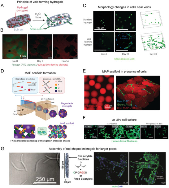
Methods to introduce macroporosity in injectable bulk hydrogels. i) Fast degrading porogens coencapsulated with MSCs in a bulk hydrogel can create voids over time, releasing the cells to the surrounding tissues A–C). A) A schematic of the process. B) Confocal images of porogens (green) degrading over time in a bulk hydrogel (red). C) Comparison of cell morphology in porogen‐free bulk hydrogel with that of cells near the voids (blue dotted line) at different time points, along with their 3D projections on the right after 40 days of in vitro culture. ii) Crosslinking of degradable microgels to produce microporous annealed particle (MAP) scaffolds D–F). D) A schematic describing the steps involved in MAP scaffold formation. E) Fluorescence microscopy images of microgels (left) and MAP scaffolds with cells growing in the pores (right). F) Images of human dermal fibroblasts forming an extensive 3D network in MAP scaffolds in comparison with the cells in non‐microporous gels at similar time points. iii) Assembly of rod‐shaped microgels to further increase pore sizes from that of MAP scaffolds: G) rod‐shaped microgels formed by microfluidics decorated with RGD moieties and coassembled with mouse fibroblasts show cell adhesion around the microgels, with large lumen in between the microgels. Reproduced by permission.[ 11 , 34 ] Copyright 2015, Springer Nature. Reproduced with permission.[ 35 ] Copyright 2019, John Wiley and Sons.
Despite the many advantages of the porogen‐based system, these porogens have to degrade before the creation of macropores, and subsequent endogenous cell infiltration and migration. Alternatively, instead of rapidly degrading porogens paving the way for cell migration and infiltration, cell loaded microgels can be dispersed inside an outer matrix hydrogel precursor solution, which may further contain other cell types. This creates a multiphase system with the ability to independently control the properties of each phase such as stiffness, cell adhesive ligand concentration, degradability, etc. facilitating the creation of niches for different cell types in one system.[ 36 ] In one example, both the microgels and matrix hydrogel were made of the same polymer obtained by crosslinking thiol‐containing peptide functionalized multiarm star polyethylene glycols (PEGs) and maleimide‐functionalized heparin via Michael‐type addition. The heparin domains thus function as a crosslinker and interact with growth factors, enabling their presentation to the cells nearby in a biomimetic manner. Both phases had different mechanical properties and were modified with variable bioactive domains, adjusted to create an in vitro vascularized prostate cancer tissue model.[ 37 ] Spherical microgels with diameters ranging from 200 to 600 µm were synthesized by microfluidics and encapsulated with human prostate cancer cells encapsulated on chip. The cells were cultured for 7 days to develop into cancer spheroids inside the microgels before mixing them into the outer phase. The microgels were stiffer compared to the surrounding matrix after crosslinking and had MMP degradable domains, which enabled degradation and remodeling of the cellular microenvironment. The soft matrix, on the other hand had cell adhesive ligands and growth factors promoting angiogenesis, in addition to MMP cleavable sites for supporting the formation of vascular networks. The matrix contained human umbilical cord endothelial cells and mesenchymal stromal cells, which upon culture along with the microgels for 5 days developed a vascularized matrix with cancer spheroids inside them, similar to the conditions in vivo. This system could potentially be used in vivo as an injectable multicellular construct for tissue regeneration.
Another innovative approach to introduce macroporosity immediately after injection is the use of microporous annealed particle scaffolds (MAPs), which is basically the inverse of the porogen‐based system. MAP scaffolds are composed of MMP degradable PEG‐based microgels, which were made using microfluidics. The microgels were modified with cell binding domains and transglutaminase peptide substrates to enable inter‐microgel covalent crosslinking under physiological conditions when injected along with activated Factor XIII to the injured site. This leads to an interconnected pore structure with pore sizes, ranging from ≈10 to 40 µm by varying the microgel diameter from ≈30 to 150 µm (Figure 1D–F). The biomechanical properties of the scaffold can thus be changed independently from the porosity. In vivo, the system resulted in the formation of extensive 3D network of cells, reduced immune responses, faster wound healing and epithelial tissue regeneration, owing to the interconnected macropores.[ 11 ] Apart from PEG, HA‐based MAP scaffolds were made with different orthogonal chemistries and showed similar cell responses.[ 38 , 39 ] The HA‐based MAP gel was used to treat a brain stroke injury and it was shown that, apart from the reduced immune response, the material reduced the scar thickness and overall gliosis and most notably recruited the neural progenitor cells (NPCs) from the subventricular zone to the stroke cavity.[ 40 ] The system is also suitable for stem cell therapies due to its ability to coinject cells.[ 41 ] Recently, it was shown that modifying the chirality of crosslinking peptides on the surface of microgels in MAP scaffolds resulted in faster degradation of the material along with accelerated cutaneous wound healing and skin regeneration in mice by the recruitment of immune cells.[ 42 ] Following the success of this approach, various researchers have used different materials to generate microgel‐annealed scaffolds, such as gelatin microgels crosslinked by microbial transglutaminase[ 43 ] or oppositely charged gelatin methacrylate and chitosan oligomer‐methacrylate.[ 44 ] The increase in porosity in such systems also promoted cell clustering and increased cytokine secretions.[ 45 ] The importance of cell–cell interactions is known for many biological functions, such as regulation of tissue homeostasis[ 46 ] and maintenance of cell stemness.[ 47 ] The large pores in these scaffolds can thus be expected to have a positive effect on tissue regeneration and stem cell expansion before differentiation. Additionally, in order to achieve even larger pores using microgels of similar volume, rod‐shaped microgels with an aspect ratio higher than one can be assembled and crosslinked (Figure 1G).[ 35 ] Due to their high aspect ratios, a randomly jammed assembly of rod‐shaped microgels can leave behind larger pores as compared to spherical microgels, which would take up a closely packed structure with smaller voids.
The MAP scaffolds have opened a new direction in injectable hydrogel materials for regenerative medicine. The nanoscale hydrogel precursor macromolecules are replaced by larger microgel building blocks, which assemble and crosslink but now resulting in much larger porosities, while still having the ability to vary the stiffness of the microgels. The system was shown to exhibit superior performance compared to nanoporous gels and porogen containing gels in terms of cell infiltration and transgene expression primarily due to the fact that endogenous cells can migrate through the matrix even before they start to degrade the matrix components.[ 48 ] Importantly, the system is fairly homogenous in terms of the pore sizes and shapes, while most native tissues do not have a uniform but rather a gradation in pore sizes.[ 49 ] Therefore, it is also important to have such gradient porosity in materials for tissue regeneration as well. Moreover, the pores in the present injectable macroporous systems are fairly isometric and homogeneous, providing minimal directional guidance for cell growth and diffusion of nutrients. The hierarchical nature of tissues, like bones, muscles, and tendons, however, demand a level of anisotropy in pore structures to achieve functional tissue regeneration. So far, multiple approaches have been presented to introduce anisometric, oriented pores in hydrogels, mainly using specific shapes of porogen.[ 20 ] Alternatively, microgels providing mechanical support have been combined with microgels that slowly release specific peptides or growth factors, for example to induce angiogenesis or immune responses, and with additional microgels that are rapidly degrading, acting as porogens to enhance porosity overtime.[ 50 , 51 ] While this approach combines different building blocks to provide a variety of functions, there is still an overall symmetry in the system when the blocks are randomly injected and then assembled.
3. In Vivo Patterning
Native tissue ECMs are not just structurally anisotropic but chemically heterogeneous in terms of the availability of biomolecules over a scale of several micrometers. This spatial nonuniformity and asymmetry is sensed by a group of leader cells, which further guide other cells over multiple length scales to coordinate their growth and organization and form well‐developed, functional tissue.[ 52 ] In homogeneous hydrogels, lack of such variations in the presentation of bioactive groups and geometry of components could adversely affect the cellular organization and tissue regeneration. Several techniques have been developed over the years to achieve spatial control over the structure and biochemistry of hydrogel scaffolds, such as stereo‐lithography, microfluidic approaches, two‐photon laser scanning photolithography, etc.[ 53 ] While many of these techniques have demonstrated cell guidance in patterned 3D systems, they are inappropriate for injectable systems in vivo, where any form of spatial control is difficult to achieve during or postinjection.
One solution is to use in vivo photopatterning, where different structures and functionalities can be precisely “printed” throughout the volume of a hydrogel. This innovative technique used light exposure to introduce bioactive groups or mechanical gradients to cells in a spatially and temporally controlled manner. Bioactive groups can be patterned in three different ways. The biomolecule can be directly coupled to the hydrogel network via light sensitive reactions,[ 56 ] the biomolecule can be crosslinked into the matrix during gelation and activated via light postinjection,[ 54 ] or an intermediate molecule with photoprotected reactive group can be incorporated in the network and bind biomolecules upon radiation.[ 57 ] In the case of biomolecule activation, hydrogels were modified during gelation with cyclic cell‐adhesive peptides that were caged by a photolabile group.[ 54 ] Upon exposure to ultra violet (UV) light in a particular spot of the hydrogels, the caging groups are cleaved, exposing the peptide chains for cell adhesion. This was also possible in vivo, which revealed that the number of adherent cells decreased progressively further away from the illumination spot (Figure 2A). Since acrylated peptides were conjugated with PEG‐diacrylates via free radical polymerization or cysteine‐containing peptides were linked to multiarm PEG‐maleimide macromers via Michael‐type addition, the hydrogel formation is compatible with many injectable systems. Another important aspect of this technique is that the time of activation of adhesive peptides can be controlled. This is important as cell‐material interactions are very dynamic in nature. For example, a delayed activation of the integrin binding domains by removing the photolabile protecting groups led to a reduced chronic inflammatory response without compromising the tissue regenerative capability of the synthetic hydrogel, as is evident from the vascularization studies. In the case of mechanical gradients, local crosslinking or degradation can also be achieved by light exposure.[ 56 , 58 ] For example, well‐defined microchannels were created by multiphoton excitation approaches[ 59 ] and photoablation using localized pulsed lasers to achieve high patterning resolution in 3D.[ 60 ] However, these systems have, to the best of our knowledge, not yet been employed after injection.
Figure 2.
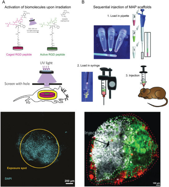
In vivo patterning. A) Photopatterning by means of a hydrogel modified by cell‐adhesive peptides caged by a photolabile group. The figure panel shows from top to bottom, a schematic of caged RGD peptide being activated by UV light exposure, followed by a schematic of the transdermal spatial patterning process and the image of adherent cell nuclei present exclusively at the illumination spot. B) Spatial patterning by the sequential injection of microgels with different biochemical or physical properties. The figures show microgels labeled with different fluorescent dyes loaded consecutively in a pipette, followed by back loading a syringe and then injection into a mouse stroke model. The microgels were then left to crosslink, forming the MAP scaffolds. The figure at the bottom shows a confocal image of a brain tissue section at the middle of the lesion obtained after two weeks. The dashed lines indicate the boundaries of each colored region. Reproduced with permission.[ 54 ] Copyright 2014, Springer Nature. Reproduced with permission.[ 55 ] Copyright 2018, John Wiley and Sons.
Unfortunately, despite the many advantages the system offers, in vivo photopatterning cannot be used in internal tissues without surgical intervention due to high attenuation and scattering effects of light when passing through several layers of the biological tissues. As most of the available techniques use UV light to pattern hydrogels, this can be problematic in vivo especially for difficult to reach tissues, as higher intensity light could cause tissue damage and induce mutations. Therefore, safer alternatives, like near infrared (NIR) light have been explored, which have the ability to penetrate tissues up to 3.2 cm for first window NIR (700–900 nm) and up to 8 cm for second window NIR light (1000–1700 nm).[ 61 ] For example, nanoparticles have been embedded inside the hydrogel to locally convert NIR light to UV light and then activate cell adhesive groups.[ 62 ] To address cytotoxicity concerns of these heavy metal nanoparticles, alternatives like semiconducting polymer nanoparticles based on poly(diketopyrrolopyrrole‐alt‐3,4‐ethylenedioxythiophene) have been explored. These locally convert NIR light into heat and cause a surrounding thermoresponsive gel to collapse releasing an encapsulated drug.[ 63 ] The same principle could be applied to locally deliver molecules like growth factors in the context of tissue regeneration. In addition to these approaches, several molecules sensitive to visible or NIR light have been developed over the years to enable localized protein release, photodegradation, and crosslinking, with a possibility to be used in injectable systems.[ 64 ] In vivo photopatterning in injectable systems, however, remains to be very challenging compared to preformed scaffolds due to the difficulties in obtaining good patterning resolution of several micrometers and the low depth of light penetration in the available systems. By introducing novel techniques and chemistries, we believe it will be possible in the future to investigate a wide range of possibilities to spatially and temporally control hydrogel systems and study the resultant cell behavior.
Alternatively, the MAP method has been adjusted and employed to achieve spatial control of biophysical and biochemical characteristics inside the gel after injection. Microgels, fluorescently labeled with different dyes, were loaded sequentially in a syringe and slowly injected. The resultant scaffold in vivo replicated the sequence of the dyes loaded in the syringe (Figure 2B). These microgels could in principle have different growth factor concentrations, or moduli or any other desired characteristic and the injection thereafter could yield a hydrogel with a gradient of different parameters from the point of injection.[ 55 ] In addition to the simplicity of the approach, this technique offers several advantages, such as the ability to be injected not just subcutaneously but even in deeper internal tissues, like the brain. Since the microgels were annealed enzymatically, light exposure was avoided. While the system offers a large flexibility over different parameters, utilization of these spatially patterned MAP scaffolds with specific functions and gradients for tissue repair are yet to be explored.
3.1. In Vivo Alignment
The ECM is composed of several fibrous proteins, such as collagens, laminins, fibronectins and elastins.[ 2 ] The orientation of such proteins in aligned tissues such as skeletal muscles,[ 65 ] nerves,[ 66 ] and connective tissues[ 67 ] are responsible for their characteristic cellular direction, morphology, and migration. Intuitively, the tissue engineering scaffolds aimed at regenerating such tissues must incorporate suitable cues in the form of aligned domains to direct the cellular orientation and migration. The traditional approaches to introduce directionality in matrices, like electrospinning,[ 68 , 69 ] strain‐induced alignment,[ 70 ] gas foaming/salt leaching,[ 19 , 71 , 72 , 73 ] directional freeze‐drying,[ 74 ] etc., are not suitable for injectable systems. Many of these scaffolds were implanted in the spinal cord after creating an injury by sectioning part of the tissue. Even though nerves were able to regenerate along the oriented fibers or through the linear channels, an open space was needed to be present to enable implantation, which is generally not the case after a spinal cord injury.[ 75 ] Other injuries that would require low invasive injectable therapeutics, while providing directionality, would be heart infarct, muscle dystrophy, etc. In the next paragraphs, we discuss recently developed approaches to introduce biomaterial alignment during or after injection in situ and cellular responses to such environments.
3.1.1. Self‐Assembling Peptides
Inspired by the self‐assembly routes in the formation of aligned tissues in living organisms during embryogenesis, an innovative technique was introduced in 2010 to align cells in a supramolecular assembly of nanofiber bundles.[ 77 ] The technique uses a dilute aqueous solution of charged peptide amphiphiles (PA), which upon heating form a micrometer‐sized plaque of fibrous texture with a crystalline order by the loss of bound water molecules. The plaque further breaks down upon cooling to form supramolecular aligned fiber bundles with a diameter of about 40 nm, which up on dragging by a pipette into a salty media at a low strain rate align over macroscopic length scales (Figure 3A–C). These fibrous domains are fixed by gelation through self‐assembly in presence of divalent metal ions in media.[ 80 ] Human MSCs and cardiomyocytes were mixed with the solution after heat treatment and cultured with the aligned strings. The cells were observed to sense the directionality of the filaments and oriented themselves along the long axis of the strings with action potentials circulating through the entire gel in case of cardiomyocytes. This proves that this technique is suitable for directing cell growth for the regeneration of aligned tissues if the solution can be injected in the direction of the aligned tissue.
Figure 3.
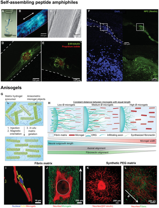
Strategies to obtain in vivo alignment. i) Self‐assembly of nanofiber bundles A–F): A) injection of a peptide amphiphile solution‐stained blue into a phosphate buffered saline after heat treatment, yielding gelled strings whose birefringence shows alignment B). C) Scanning electron microscopy of the strings revealing aligned nanofiber bundles. NPC neurospheres encapsulated in aligned D) and unaligned E) IKVAV modified PA gels show differentiation into neurons with the neurite extension and alignment significantly larger in aligned gels as compared to unaligned ones. F) Injection of IKVAV modified PA gels premixed with NPCs into an adult rat spinal cord exhibits local cell alignment. Dashed lines show the scaffold boundaries. ii) Magnetically aligned microelements in an injectable hydrogel matrix forming an Anisogel G–L). G) A schematic describing the formation of an Anisogel, H) A diagram showing the dependence of neurite outgrowth and alignment with the cross‐sectional dimensions of the microgels in an Anisogel. I) Fibroblasts aligning along the direction of aligned microgels in fibrin gels. J) Neurites from DRGs aligning along the direction of oriented microgels in a surrounding fibrin matrix. K) DRG outgrowth in synthetic PEG gels, modified with MMP sensitive crosslinks and a recombinant fibronectin fragment but without microgels show neurite growth in all directions while, L) DRGs in oriented Anisogels show aligned neurite outgrowth. Reproduced with permission.[8, 76 ] Copyright 2017, 2019, American Chemical Society (ACS). Further permissions related to excerpts from these materials should be directed to the ACS. Reproduced with permission.[ 77 ] Copyright 2010, Springer Nature. Reproduced with permission.[15, 78 ] Copyright 2018, 2014 Elsevier. Reproduced with permission.[ 79 ] Copyright 2020, John Wiley and Sons.
In a next stage, the platform was made cell‐adhesive by partially coupling the PA with ECM‐derived peptides, like IKVAV and RGDS. IKVAV modified PA scaffolds enhanced the neuronal differentiation, neurite growth, and neurite alignment in the direction of filaments (Figure 3D,E), but had a slightly reduced level of alignment compared to unmodified PA. The neurons matured to form synaptic connections, thus propagating electrical signals in a directional manner. Most importantly, these scaffolds were shown to be injectable in vivo into a rat spinal cord with NPCs encapsulated in them (Figure 3F).[ 78 ] PA conjugated with different peptide sequences demonstrated to guide the migration of neuroblasts in rat brain[ 81 ] and PA containing growth factors enhanced intramuscular transplantation of muscle stem cells in vivo.[ 82 ] Further, these gels are degraded within a month in vivo with the degradation products being naturally occurring amino acids and lipids allowing for fast clearance[ 83 ] and their modulus can be tuned precisely by varying the chain length of oligo‐l‐lysines, which acts to crosslink the fibers.[ 84 ] Growth factors can be bound to the supramolecular assemblies as well for enhanced tissue regeneration.[ 83 ] Moreover, the hierarchical structure of the gels can be controlled much like the native ECM by modifying the cohesive forces between the peptide assemblies.[ 85 ] Interestingly, the coassembly of alkylated peptides and peptide–DNA conjugates form superstructures containing twisted filament bundles, which can be disassembled reversibly by the addition of oligonucleotides or changes in temperature.[ 86 ] In conclusion, the self‐assembled PA are a very versatile platform to form oriented and injectable scaffolds, with their ability to modulate the gel modulus, bioactivity, structure and even the fiber length.[ 87 ] Although it has to be noted that the alignment of fibers is always along the direction of injection and cannot be controlled independently.
Several other types of supramolecular hydrogels have been developed alongside the PA to allow for the formation of injectable hydrogels with fibrous domains as a potential tissue regenerative scaffold. One among them is polyisocyanopeptide (PIC) with oligo (ethylene glycol) side chains, which forms a helical architecture in solution much like the cytoskeletal intermediate filaments and exhibits a reversible thermally induced gelation. Upon gelation, the PIC chains bundle up to form a fibrous material, which goes back to a solution state when the temperature is lowered allowing cellular recovery. Apart from the coupling of bioactive groups, the gel modulus and gelation temperature can be modified by changing the polymer chain length to make the system suitable for in vivo applications.[ 88 ] The gel porosity can be controlled by varying the polymer concentration while the bundle diameter remains constant. Apart from being highly modular, these gels also exhibit a stress‐stiffening effect similar to natural fibrin or collagen gels. Although alignment of the cells in these gels has not been quantified in particular, observations of fiber alignment in some of these gels and subsequent effects on cellular orientation have been reported.[ 89 ]
3.1.2. Magnetic Alignment
Early reported use of a magnetic field to create anisotropic tissue regenerative substrates employed magnetic alignment of collagen or fibrin fibrils, owing to their diamagnetic susceptibility, for the purpose of peripheral nerve regeneration. This method however, is limited for use as injectable system in vivo due to the requirement of a very strong magnetic field of about 9.4 T and was therefore employed to prefill nerve guidance conduits with these magnetically aligned gels for later surgical implantation.[ 90 , 91 ] To overcome this drawback, an injectable platform with the ability to be magnetically aligned in vivo was introduced, which utilizes superparamagnetic iron oxide nanoparticles (SPIONs) dispersed in a collagen matrix. These particles under an external magnetic field (25.5 mT) aggregate, forming long and aligned strings in the direction of the applied field. The collagen precursor solution, which forms a hydrogel in the meantime fixes this alignment and the collagen fibers in turn are oriented. The combined effects of oriented collagen fibers and magnetic particle strings were able to align neurons.[ 92 ] A similar approach was utilized in Matrigel and HA hydrogels using protein‐coated magnetic nanoparticles.[ 93 ] However, the clinical use of such systems could be problematic due to the requirement of a high dose of large sized nanoparticles, which can take a long time for clearance and cause cytotoxic effects.[ 94 , 95 ] Alternatively, collagen fibers were aligned during bioprinting as magnetic iron nanoparticles travel through the bioink during crosslinking by simply holding a magnet to one side of the solution.[ 96 ] In this case, most of the magnetic particles would assemble on the edge and could potentially be removed after injection. In vivo, this may not always be possible depending on the tissue and its orientation.
Instead of using SPIONs to introduce anisotropy in injectable systems, cellulose nanocrystals (CNCs), sourced from natural materials, have been magnetically aligned perpendicular to a magnetic field due to their inherent diamagnetic properties. They have high aspect ratios with a length of 100−200 nm and cross‐sectional dimensions of 5−20 nm, and are considered nontoxic. CNCs cannot be degraded in vivo but a minimal aggregation of these particles when dispersed in poly(oligoethylene glycol methacrylate) (POEGMA) hydrogels allows for a fast clearance from the body. This is observed from the bio‐distribution studies done after subcutaneous injection of the nanocomposite hydrogel in mice.[ 97 , 98 ] When CNCs were dispersed in reactive POEGMA hydrogel precursor solutions and coinjected under a magnetic field (1.2 T), they aligned perpendicular to the field direction, during which both hydrazide and aldehyde‐functionalized POEGMA crosslinked as a surrounding matrix via dynamic covalent hydrazone bonds. Mouse myoblasts cultured inside this 3D matrix were initially unaligned but later differentiated to form aligned myotubes, following the orientation of CNCs.[ 99 ] Since the CNCs are nanometer sized particles with dimensions much smaller than the cultured cells, it is hypothesized that the alignment of myotubes is primarily caused by the cells sensing the anisotropy in stiffness and surface properties of the aligned particles. When injected and crosslinked subcutaneously in mice, the presence of aligned CNCs inside the gels increased cell infiltration after 30 days as compared to gels containing unaligned CNCs and only mild acute and chronic inflammatory responses were observed in both cases.[ 97 ] However, the CNC orientation was insufficient to align the fibroblasts or other smaller cell types like myoblasts. Since the natural extracellular fibers, like collagen, have diameters in the range of 1–20 µm,[ 4 , 100 ] control over larger cross‐sectional dimensions of the anisometric components of the system could be beneficial in inducing cellular alignment.
To provide aligned directional cues with defined dimensions inside an injectable 3D hydrogel, our research group developed a hybrid system, called Anisogel.[ 8 ] It is comprised of SPION containing rod‐shaped microelements, which are aligned inside a natural fibrin[ 8 ] or synthetic[ 15 , 76 ] hydrogel matrix parallel to the field lines of an external magnetic field (100 mT) in less than a minute.[ 101 ] As the microelements orient, the matrix around them crosslinks, preventing their further movement even after the removal of magnetic field (Figure 3G–L). Owing to their high aspect ratio, the concentration of SPIONs required to align the microelements is very small, resulting in an overall SPION concentration of merely 1.8 ng µL−1 or 0.0046 vol% in the entire Anisogel when microgels occupy 0.45 vol%.[ 79 ] Neurons and fibroblasts cultured in Anisogels oriented in the direction of the aligned rod‐shaped microgels or short fibers.[ 15 ] While the microgels were fabricated from bioinert PEG using an in mold polymerization method, the short fibers were prepared from poly (lactide‐co‐glycolide) via an electrospinning/microcutting technique. In the case of the PEG microgels, aligned cells thus mainly interacted with the surrounding cell‐adhesive matrix. By pulling on the matrix via their integrins, we believe that cells sense a different mechanical response from the matrix in the direction of or perpendicular to the oriented microgels. In the case of fibroblasts, 1.5 vol% microgels with dimensions of 5 × 5 × 50 µm and an average inter‐microgel distance of ≈28 µm was sufficient to induce cell alignment, while neurites already grew in a unidirectional manner in the case of 1 vol% microgels with an average inter‐microgel distance of ≈34 µm. When the vol% of microgels was increased, more nuclear YAP shuttling was observed, suggesting that cells sense the overall anisotropic mechanical properties of the Anisogel. Interestingly, the fibronectin produced by the aligned fibroblasts was also oriented parallel to the microgels, demonstrating that a naturally aligned ECM matrix could take over the function of the microgels over time, after they would degrade. Furthermore, the system is versatile with the possibility to modify the physical, mechanical, and biochemical properties of the microelements and the surrounding gel independently from each other. For example, magneto‐responsive GRGDS‐modified PEG‐based rod‐shaped microgels led to a stronger interaction between the cells and the microgels but only a small enhancement in fibroblast alignment. This stronger interaction, however, also led to a reduced fibronectin production and thus a possible impairment of the positive feedback cycle described above, where the naturally formed ECM would be oriented and replace the artificial Anisogel during tissue regeneration. This emphasizes that overstimulating the cells with signaling cues may not always be the best approach but instead, providing a minimum of signals to jump‐start the regenerative process could be more efficient, by helping and letting biology do its magic. Within this objective, smaller microgels with a width of 2.5 µm resulted in enhanced neurite extension, likely due to the fact that axons were less hindered by the cross‐sections of the microgels. Cutting the microgel width by half, while reducing the inter‐microgel distance from ≈34 to ≈24 µm resulted in an increase in neurite alignment, even if the length was also decreased from 50 to 25 µm. These 2.5 × 2.5 × 25 µm microgels only took up 0.45 vol% of the entire Anisogel (Figure 3H).[ 79 ]
Besides the microgels, short fibers were produced and aligned inside the Anisogel resulting in spontaneous electrical activity of the aligned axons with calcium signals propagating along the anisotropy axis of the material. Short fibers have the advantage that their surface nanotopography can be adjusted between smooth, porous, and grooved, leading to higher neurite alignment in the case of nanogrooves[ 102 ] on the fibers and enhanced morphological aspect ratios and nuclear YAP shuttling in the case of fibroblasts.[ 103 ] When comparing similar dimensions and vol% of aligned fibers and bioinert PEG microgels inside a synthetic PEG‐based Anisogel, modified with engineered fibronectin fragments and MMP sensitive crosslinkers, neurites aligned slightly better in the case of the cell adhesive fibers.[ 76 ] Extensive in vivo experiments are yet to be performed with Anisogels. Meanwhile, a combination of both described approaches was introduced in the form of rod‐shaped CNCs decorated with magnetic iron oxide nanoparticles. These rods were further coated with bioinspired polydopamine to surface functionalize the CNCs with PEG brushes to enhance their colloidal stability and biocompatibility, yielding PEGylated, magnetic nanoparticle decorated CNCs with a diameter around 19 nm and aspect ratios in the range of 10–20.[ 104 ] A low concentration (0.1−0.5 wt%) of these modified CNCs were loaded in a gelatin matrix and a magnetic field as low as 108 mT could induce their alignment, now parallel to the magnetic field lines. Moreover, the overall iron oxide concentration in the hydrogel was only 0.0005 vol%, thus even lower than for Anisogels. While iron oxide nanoparticles are responsible for the alignment of these modified CNCs, the synergy between the rod shape of the CNCs and the aligned domains of the CNCs decorated with SPIONs creates anisotropic hydrogels. Encapsulation of human adipose tissue derived stem cells showed alignment along the anisotropy axis of the composite gel. Even though the CNC concentration window, over which good cell viability and cellular orientation occur is limited to 0.1–0.2 wt%, the system offers yet another tool for the remote alignment of cells in vivo.
A completely different approach to self‐assembly or magnetic alignment is the use of entangled microstrands produced by passing pre‐crosslinked bulk hydrogels through a perforated grid with pore sizes ranging from 40 to 100 µm. These microstrands are printable and upon extrusion through a syringe form aligned structures. When myoblasts were mixed inside a gelatin‐based bulk hydrogel, which was later extruded to form entangled strands, oriented myotubes were obtained after differentiation.[ 105 ] The extrusion process did not impair cell viability and >90% cell viability was observed. Similarly, droplet microfluidics was employed to form cell‐laden microgels of high aspect ratios with diameters ranging between 50 and 300 µm and lengths of a few millimeters, which could then be printed to form desired patterns.[ 106 ] Different cell types cultured in such microrods had an oriented morphology along the length of the microrods. Both printing methods also benefit from the anisometric shape of the building blocks to achieve macroporous constructs. Although in vivo studies have not been performed yet on these gels, the approach still holds promise to form anisotropic tissue regenerative scaffolds for oriented cell growth.
4. In Vivo Bioprinting
Instead of a one‐time injection in vivo, where programmed building blocks assemble into a 3D construct with a specific architecture and mechanical and biochemical properties, in vivo bioprinting has emerged as an innovative method to deposit regenerative biomaterial structures and potentially cell and biomolecules in situ. Currently, most bioprinting technologies are still being developed and tested in vitro, requiring two necessary steps before their application inside the body: i) tissue maturation inside a bioreactor and ii) transplantation inside the patient's body.[ 107 ] The essential nature of these steps is linked to complications, such as construct biocompatibility, conduction of cellular proliferation, controlled degradation rate, ECM recapitulation, vascularization, and dynamic scaffold shape modification. In contrast, in vivo bioprinting has proven effective for injection of cell‐laden bioinks at the defect site.[ 108 ] Its clinical translation is advantageous for scanning the defect area and deposition into the wound site over conventional 3D construct implantation, while eliminating the need to reshape the scaffold according to defect geometry. This aspect is highly desirable for irregular shapes and architectures.[ 109 ] Importantly, in vivo bioprinted constructs mature inside the body, making use of the native ECM, biomolecular signaling, and mechanical forces naturally present at the defect site to provide physical support and instructive cues to infiltrating endogenous or printed cells. These characteristics are absent in bioreactor‐based maturation, which may still present shortcomings and reduced effectiveness compared to its in vivo counterpart. For autologous cell sources in particular, exploiting the surrounding microenvironment as a “natural bioreactor” is a convenient and efficient step toward definitive tissue integration. In addition to reducing the possibility of rejection, it is accompanied by superior shape fidelity, lower infection risk, presence of developmental cues and reduced maintenance costs compared to other cell sources, and to additive manufacturing techniques which rely on implantation and potential maturation ex vivo.[ 110 , 111 , 112 ]
Similarly to conventional in vitro bioprinting, in vivo bioprinting also makes use of extrusion, inkjet, or laser technologies. Extrusion bioprinting works through continuous bioink extrusion via a nozzle (Figure 4A). Despite its limited resolution (i.e., ≈200 µm), it offers significantly higher printing speeds. Yet, cell death due to shear stress is one of its main drawbacks.[ 107 ] Inkjet bioprinting, on the other hand, employs sequential bioink droplet deposition through a nozzle with high resolution (≈20–100 µm) and processing speed, and is associated with a relative lower cost compared to other methods (Figure 4B). Moreover, the printing stage does not have to be flat, which represents an important benefit.[ 120 ] However, existing drawbacks are clogging due to high cell density, nonuniform droplet sizes, and limited material choice due to viscosity requirements (<10 mPa s−1).[ 108 ] Enhanced cell viability can be achieved by laser induced forward transfer (LIFT), enabling deposition at the individual cell level (Figure 4C). Focused laser pulses trigger evaporation of the absorbing layer, propelling the bioink toward the site of interest.[ 118 ] Despite high cost and slow printing speed, LIFT is a nozzle‐free approach for precise deposition of viscous materials and capable of high resolution.[ 121 ] Many in vivo bioprinting techniques rely on injecting or printing a photoactive biopolymer underneath the skin or in tissues, which can then be crosslinked with light (Figure 4D). Proof of concept studies have bioprinted cartilage and muscle using NIR light with longer wavelength (>800 nm), which allows for deeper tissue penetration compared to UV.[ 122 , 123 ] Another potential avenue for the translation of bioprinting is the combination of embedded 3D printing, currently capable of producing accurate but nonfunctional structures, with controlled cellular deposition via the aforementioned bioprinting technologies.[ 124 ] Depending on future developments in material research, the topology of organs could be recreated using a cell‐supporting biomaterial, thus facilitating cell printing while achieving high‐fidelity structure replication
Figure 4.
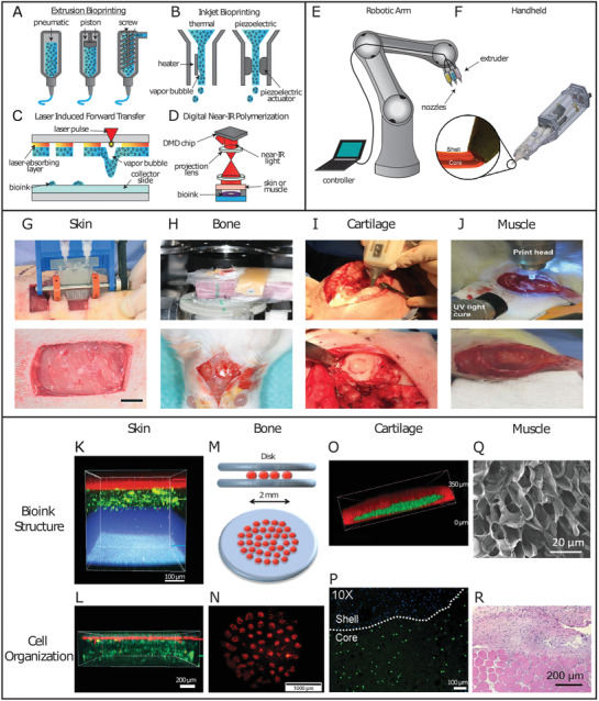
Schematic representation of additive manufacturing techniques, their implementation and possible tissue applications in vivo. A) Examples of extrusion bioprinting induced through different driving forces, such as pneumatic pressure, mechanical pressure through a piston, or a screw extruder. B) Inkjet bioprinting performed through formation of a vapor bubble, allowing droplet formation, or via a piezoelectric actuator. C) LIFT bioprinting, which propels bioink droplets onto the collector slide through laser pulses forming vapor bubbles. D) Digital near‐infrared polymerization setup to crosslink an injectable photoresponsive biopolymer intravitally. E) A remote‐controlled robotic arm setup for in vivo bioprinting. F) The Biopen handheld extrusion device capable of core–shell geometries for an enhanced protective effect on the bioink core. Reproducedwith permission.[ 113 ] Copyright 2017, Springer Nature. G) In vivo bioprinting of skin sheets using a handheld extrusion device (scale bar: 10 mm). Reproduced with permission.[ 114 ] Copyright 2018, Royal Society of Chemistry. H) In vivo LIFT bioprinting to fill calvaria defects in mice. Reproduced with permission.[ 115 ] Copyright 2009, IOP Publishing. I) The Biopen handheld extrusion device, in use to fill condyle defects. Reproduced with permission.[ 116 ] Copyright 2017, John Wiley and Sons. J) In vivo bioprinting of muscle to address VML in mice. Reproduced with permission.[ 117 ] Copyright 2020, John Wiley and Sons. K) Confocal image of three‐layer hydrogel for wound repair. Top to bottom: alginate layer with Nile red microparticles, alginate‐collagen layer with FITC‐conjugated collagen, and fibrin‐HA layer with blue microparticles. Reproduced with permission.[ 114 ] Copyright 2018, Royal Society of Chemistry. L) Confocal image of bilayer alginate bioink with keratinocytes embedded in the top layer (k14 + phalloidin costain, red), sequentially deposited on top of fibroblasts (phalloidin, green), resembling the bilayered structure of skin. Reproduced with permission.[ 114 ] Copyright 2018, Royal Society of Chemistry. M) Schematic representation of the in vivo disk geometry deposited with laser based bioprinting to fill calvarial defects in mice. The collagen bioink layer with seeded BMSCs is sandwiched between two layers of n‐HAp. Reproduced with permission.[ 118 ] Copyright 2017, Springer Nature. N) Fluorescent image of tomato‐stained BMSCs immediately after being printed in disk conformation. Reproduced with permission.[ 118 ] Copyright 2017, Springer Nature. O) Confocal image of the core/shell geometry used by the Biopen for cartilage regeneration. The shell (GelMA/HAMa plus 0.1% LAP) is shown in red, while the core (GelMA/HAMa) is shown in green. Reproduced with permission.[ 113 ] Copyright 2017, Scientific Reports. P) Confocal image of the Biopen's core/shell bioink structure, with bioprinted ADSCs stained with Calcein‐AM (live cells, green channel) at day 1 after printing. Reproduced with permission.[ 113 ] Copyright 2017, Scientific Reports. Q) Scanning electron microscope image of 5% crosslinked GelMA hydrogel showing pores with a >1 µm diameter facilitating cellular infiltration to treat VML. Adapted with permission.[ 119 ] Copyright 2020, American Chemical Society. R) H&E histological staining showing the interface between skeletal muscle tissue and in situ printed scaffold, harvested 4 weeks postop. Evidence of scaffold integration, as well as cellular proliferation and migration are visible. Adapted with permission.[ 119 ] Copyright 2020, American Chemical Society.
Through the development of novel technologies with the aforementioned benefits, a path toward tissue engineering capable of resolution at the single‐cell level and of depositing structures indistinguishable from the native counterparts, is being laid but a long road is still ahead of us. Thanks to the potential for direct complex structure replication, in vivo bioprinting has the possibility of bringing the field toward this goal. While in vivo bioprinting is still in its preliminary stage of application, below you find an overview of its progress for skin, bone, cartilage, and skeletal muscle.
4.1. Skin
Skin is considered a valuable candidate in the early stages of in vivo bioprinting, given its apical position and ease of access. As the largest organ in humans and the first barrier against external aggressors, skin is a common injury site with a complex wound healing procedure. Because of its stratified structure comprising different cell populations, a high degree of spatial control is required when positioning specific cellular identities. Moreover, skin is mostly flat, which facilitates replication of the different physiological cell layers, morphological fidelity, and biological correspondence. Therefore, in vivo skin bioprinting makes for a practical less‐invasive approach.
Using an in‐house extrusion bioprinter, a photo‐crosslinkable natural heparin‐HA bioink containing amniotic fluid‐derived stem cells (AFSCs) has been employed to treat skin wounds in mice.[ 125 ] AFSCs were chosen due to their high proliferation capacity, multipotency, and lack of significant immunogenicity.[ 126 ] Despite UV light‐dependent crosslinking, cytotoxicity was not induced and after 14 days, 99.8% wound closure, 99.2% re‐epithelialization and 83.5% wound contraction were achieved.[ 125 ] Alternatively, by combining a handheld 3D laser scanner and an inkjet printer, accurate identification and measurement of wound topologies could be merged with multicellular delivery in precise spatial multilayers.[ 110 ] Depending on the dermal layer, either fibroblasts or keratinocytes were deposited within fibrin/collagen type I hydrogels in a porcine wound model, mimicking the epidermis and full dermis.[ 110 ] Early epithelialization with almost complete wound coverage was achieved after 14 days by the autologous group, with an overall acceleration of 4–5 weeks in epithelialization, 3 weeks in wound closure, and 50% reduction in wound contraction, compared to other cell sources.[ 110 ]
Handheld extrusion bioprinting systems have been used to treat skin wounds, where a uniform matrix is preferable and precision is less crucial. Homogeneous sheets of alginate and fibrin/HA were printed to cover skin wounds in murine and porcine models (Figure 4G,K,L).[ 114 ] These reached hemostasis after ≈5 min, while the untreated controls took tens of minutes. Complete re‐epithelialization was achieved in 75% of the treated wounds, compared to only 25% in untreated controls after 20 days.[ 114 ] Notably, this technical approach allowed for printing speeds of 0.3–1.6 cm2 s−1, significantly faster than conventional extrusion bioprinters, highlighting their potential benefits when a defined architecture is not required.[ 114 ]
Despite recent promising results, current in vivo bioprinting of skin has been limited to the use of only fibroblasts or keratinocytes. Therefore, further studies are required to implement additional cell types to recapitulate structures like sudoriferous glands, blood vessels, and nerves, when aiming at full thickness skin regeneration. Yet, the steps taken in recent years are laying the foundation for a future, where burn and wound reconstruction will become possible with minor operations and minimal complications.
4.2. Bone
Bone is a highly vascularized connective tissue with a complex structure mainly composed of calcium phosphate and collagen.[ 127 ] Long bones contain anisotropic architectures compared to flat or short bones, manifested with differing geometric microstructures, as well as oriented cell populations and vascular canals. Owing to its vascularized nature, bone is capable of self‐healing and regeneration in response to injury or trauma. However, at critical size bone defects, where the self‐healing property of bone is not sufficient to fill the injury gap, in vivo 3D‐printed polymeric scaffolds have shown many advantages, as they can be fabricated according to the specific shape of the defect area and promote matrix mineralization and new bone formation.[ 115 , 118 , 128 ] Moreover, direct cellular deposition with a nanohydroxyapatite (HAp) bioink into the defect area through in vivo bioprinting would solve integration issues between construct and host, which have been commonly observed with conventional 3D preprinted scaffolds.[ 129 ]
In an early attempt to use in vivo bioprinting for bone tissue regeneration, LIFT bioprinting was used to deposit HAp, a structural mineral component of bone playing a key role in promoting osteoconduction, in 4 mm wide mouse calvaria defects (Figure 4H).[ 115 ] Out of 30 mice, 29 recovered from the operation without infections or neurological disorders.[ 115 ] Due to laser irradiation, edema was present under the dura mater at day 7, which disappeared by day 21. Mature bone tissue was observed in test sites at 3 months postop.[ 115 ] As a follow‐up study, murine bone marrow stromal cells (BMSCs) embedded in a collagen type I‐HAp hydrogel were bioprinted in mice calvaria defects, with acellular hydrogels as controls (Figure 4M).[ 118 ] To evaluate the effects of cellular distribution on gap filling, cells were deposited in the defect within the collagen I bioink in between two HAp layers in a disk configuration in the center or in a ring shape in the outer circumference (Figure 4N). Printed disk conformations with BMSCs were the most effective, with a bone/tissue volume formation significantly larger than with the ring conformation, and even more so than the acellular collagen/HAp hydrogel alone at 1 and 2 months postsurgery.[ 118 ] Another significant in vivo bioprinting study took advantage of the tissue's highly vascular nature to induce bone regeneration via endothelial cell deposition using LIFT.[ 128 ] Significant improvements in bone formation, vascularization rate, and vessel density were observed after 2 months.[ 128 ] To ensure a more widespread implementation of these approaches, efforts need to be focused on enhancing deposition speed and surface area, as well as vascularization and long term tissue integration.
4.3. Cartilage
Hyaline cartilage presents unique morphological and structural characteristics. Chondrocytes are the only cell type present and are distributed in a columnar manner. Hyaline cartilage is therefore arranged in several layers which differ in cellular shape, density and metabolic state. Hyaline cartilage possesses load‐bearing capacity thanks to the presence of negatively charged glycosaminoglycans, which attract water molecules, and collagen fibers parallel and perpendicular to the joint surface in the superficial and deeper zones, respectively, to ensure appropriate load‐bearing qualities. Until recently, hyaline cartilage was considered incapable of undergoing regeneration. While this assumption still holds true in terms of its natural capabilities, several advancements have been made in recent years. The so‐called “Biopen” has been developed as a handheld 3D bioprinter, which extrudes bioinks simultaneously through a nozzle and subsequently photocures them with a UV light source (Figure 4F).[ 130 ] Using a mixture of gelatin methacrylic anhydride and HA methacrylic anhydride (GelMA/HAMa), the Biopen has been employed to bioprint adipose tissue‐derived stem cells (ADSCs) and fill femoral condyle defects in an ovine model (Figure 4I).[ 130 ] GelMA presents significant advantages in terms of tunability, cytocompatibility, presence of moieties, such as RGD and MMP‐degradable peptides, and low manufacturing cost. Potential downsides lie on batch reproducibility, immunogenicity, limited mechanical strength and the need of a photoinitiator (PI) to induce light‐mediated crosslinking.[ 131 ] Moreover, depending on the species origin of gelatin, it can represent a source of endotoxins and consequent inflammation.[ 132 ] Endotoxin content differs greatly between sources, with skin‐derived porcine type A gelatin measuring 13.3 EU mg−1, while bone‐derived bone type B measured 0.02 EU mg−1.[ 133 ] Bovine type A gelatin has been reported to induce an inflammatory response in vitro, while bovine type B gelatin did not trigger inflammation, neither in vitro or in vivo.[ 132 , 133 ] In addition to bovine, low endotoxin gelatin alternatives are derived from cold water fish skin, capable of protection against free radicals.[ 134 ] Importantly, in the Biopen study, only a small 3% decrease in cell viability was observed at day 1 between nonencapsulated control cultures and cured gel (with and without bioprinting), potentially due to the application of UV light or contact with the PI, while this reduction in cell viability disappeared by day 3.[ 130 ] In the process toward translation into clinical practice, a coaxial system was developed for the Biopen, allowing for crosslinking of the outer bioink layer without affecting the viability of the cells embedded in the inner layer (Figure 4O).[ 113 ] A GelMA/HAMa hydrogel was once again used, with ADSCs embedded in the non‐crosslinked core, while lithium phenyl‐2,4,6‐trimethylbenzoylphosphinate (LAP) was mixed as PI with the shell precursor solution to induce crosslinking (Figure 4P). This enabled the cells to retain proliferative capacity and undergo less cell death compared to non‐coaxial geometries or other types of PIs (e.g., Irgacure 2959 and VA‐086).[ 113 ] Segregation of LAP to the outer core enabled the stiffer crosslinked shell to provide structural support and a protective effect for the soft cell‐laden core. When employed for chondral defect repair in an ovine model, animals treated with the Biopen presented statistically significant improvement in macroscopic tissue appearance compared to implantation of ADSC‐seeded scaffolds prepared in vitro, conventional microfracture technique, and the untreated group.[ 116 ] Evidence showed a higher amount of newly regenerated cartilage, as well as columnar alignment of chondrocytes, and absence of subchondral bone deformation or collapse.[ 116 ]
In contrast to the manually controlled Biopen, robotics can be employed in a surgical environment (e.g., da Vinci Surgical System) with a higher degree of control, seamless transitions between surgical stages, and minimal real‐time complications (Figure 4E). A recently developed robotic arm, which allowed for 6 degrees of freedom was used to deposit a HAMa hydrogel crosslinked with acrylate‐terminated four‐armed polyethylene glycol.[ 135 ] The tissue was evaluated macroscopically using the International Cartilage Repair Society scoring system, ranking the degree of defect repair, integration to border zone, macroscopic appearance and overall repair assessment. For all four categories, the implantation and in vivo bioprinting groups showed statistically significant improvements compared to untreated controls but no differences were observed between the implanted and bioprinted construct.[ 135 ]
4.4. Muscle
Skeletal muscle has an intrinsic ability to regenerate following damage thanks to satellite cells, a stem cell population, which resides between the sarcolemma and the basal lamina of myofibers. Despite the presence of satellite cells, muscle can undergo extensive damage and atrophy under specific circumstances. Muscle wasting can originate from conditions like muscular dystrophy or Pompe disease, or as a consequence of trauma or surgery. This is eventuality named volumetric muscle loss (VML) and is characterized by skeletal muscle destruction, incomplete regeneration, and fibrosis.[ 119 ]
Myofibers possess a high degree of directionality and require anisotropy to direct flexion. Furthermore, their innervated nature should be considered to achieve proper functionalization and morphological recapitulation. Skeletal muscle contracts as a result of neural stimulation, which interfaces through the neuromuscular junctions. Current treatments to induce muscle regeneration consist of autologous transplants from an uninjured site or scaffolds, but both often fail in terms of functionality and integration due to inherent fibrosis.[ 136 , 137 ]
Recently, steps have been taken to introduce in vivo bioprinting for skeletal muscle repair. Using a handheld extrusion bioprinter, photo‐crosslinkable GelMA has been deposited without cells into VML defects in mice. GelMA was selected for its rapid crosslinking and subsequent tissue adherence (Figure 4Q).[ 119 ] In vivo bioprinting of GelMA allowed for superior control over construct geometry, crosslinking and adhesion to the surrounding tissue.[ 119 ] The hydrogels supported the formation of multinucleated myotubes in vivo and compared to no‐treatment groups, muscle tissue presented an average of 25% increase in size when bioprinting was used (Figure 4R).[ 119 ] Another study employing the same technique used GelMA in combination with laponite nanosilicate and mouse myoblasts in a murine model (Figure 4J).[ 117 ] Silicon‐based polymers like laponite are potent nano‐reinforcers and have been used in tissue engineering to create self‐healing hydrogels formed by ionic interactions that are capable of providing load‐bearing support, especially in orthopedic applications where laponite has shown to induce differentiation of BMSCs into osteoblasts.[ 138 ] Interestingly, immediately after recovering from surgery, the animals showed the ability to load and flex the surgical limb with sufficient grip strength to perform normal activity.[ 117 ]
In conclusion, given the complex and multifactorial nature of in vivo bioprinting, the challenges to be overcome are manifold: an integrated 3D scanner capable of accurate defect mapping needs to be coupled with an intuitive user interface to establish the bioprinting pattern, including necessary tissue structure and hierarchy. Subsequently, a reliable printing mechanism is required that combines high resolution and shape fidelity, low cost, high cell viability, as well as structural and mechanical performance. Despite macroscopic layer by layer printed structures in vivo, there is still a lack of suitable techniques and proof for printing anisotropic structures at scales similar to the natural ECM. Furthermore, there is a need for clinically approved bioinks enabling instant gelation inside the body using nontoxic crosslinking mechanisms, ideally without making use of UV or PIs. Developing a bioink that possesses both a bioprinting‐friendly density and viscosity without affecting cell viability, while resulting in crosslinked constructs with defined shapes and appropriate mechanical properties for cell growth is still difficult to achieve. For more information on this topic, we refer the reader to recently published review papers about bioinks.[ 139 , 140 , 141 , 142 ] The lack of suitable bioinks is, therefore, currently one of the biggest bottlenecks for in vivo bioprinting. Combining the structural building blocks mentioned above with emerging in vivo bioprinting techniques opens many new opportunities to achieve hierarchical structures down to the nano‐ to micron‐scale. The different methods employed to fabricate these injectable programmed or responsive elements are summarized in the next section.
5. Methods to Produce Injectable Building Blocks for Hybrid Hierarchical Biomaterials
Having established the need to introduce a hierarchy and anisotropy in the tissue engineering platforms, we here focus on the techniques to fabricate the components for making such injectable systems. Various injectable precursors to produce bulk hydrogels for tissue repair have been reviewed in detail before.[ 10 , 22 , 143 ] Many nanoparticle‐based approaches mentioned in this review rely on the aggregation of particles to form aligned domains, similar to self‐assembly of peptide amphiphiles to form nanofibers. Below, we emphasize on the production of the microelements that would assemble after injection with or without the presence of another hydrogel precursor. To achieve control in assembly, the uniformity of shapes and sizes of these microelements are of great importance, along with the ease of fabrication. Five important techniques to produce injectable building blocks are discussed below: lithography, particle replication in nonwetting templates (PRINT), microfluidics, stop‐flow lithography, and electrospinning.
The first papers on fabrication of microgels for regenerative purposes used lithography techniques, primarily photolithography, which uses a photo‐crosslinkable thin polymer film being exposed to UV light with a patterned mask in between. Only the light exposed regions of the film crosslink or degrade, while the unwanted regions can be washed away using a suitable solvent (Figure 5A).[ 150 ] The resolution and microgel shapes that can be obtained by photolithography is limited by the wavelength of the light, as well as the patterns on the mask, respectively. Polydispersity in size of these microparticles are also quite high in traditional photolithographic processes.[ 144 ]
Figure 5.
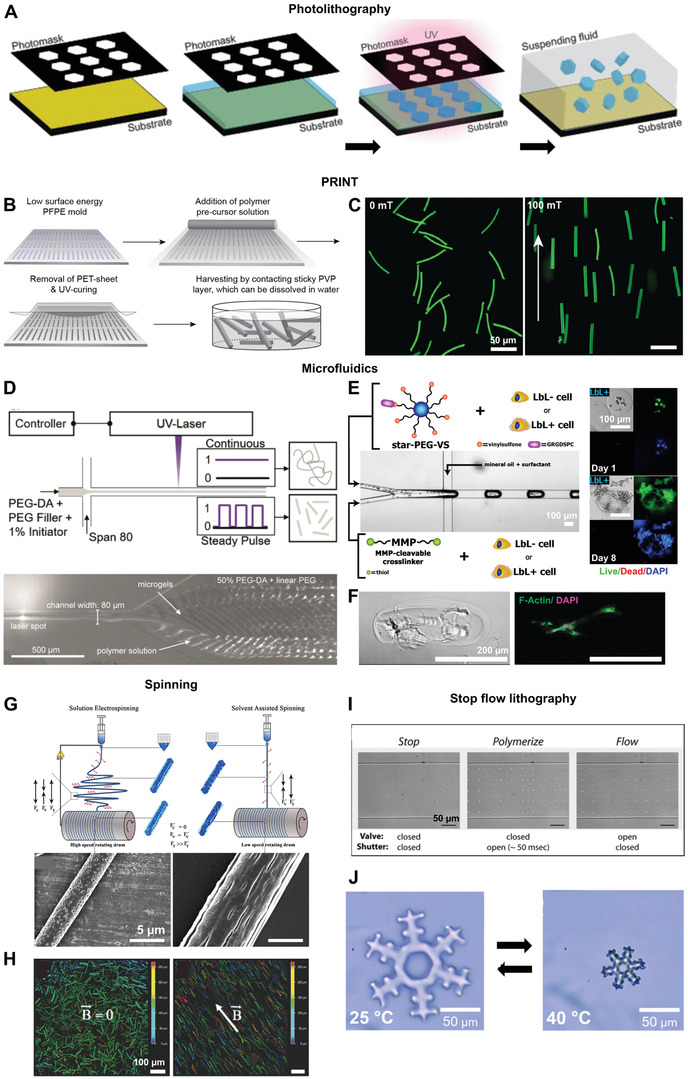
Techniques to produce building blocks for introducing hierarchical structures in injectable biomaterials: i) photolithography A), ii) PRINT B,C), iii) Microfluidics D–F), iv) Spinning G,H) and v) Stop flow lithography I,J). A) A schematic describing the process of photolithography. B) The steps involved in the PRINT process. C) Magnetoceptive PRINTed microgels randomly oriented in the absence of a magnetic field on the left and oriented in the direction of a 100 mT magnetic field on the right. D) A schematic of the process of compartmentalized jet polymerization to produce thin microgels by microfluidics (top) and microgels formed at the outlet of a channel after exposure of the jet to a pulsating UV laser (bottom). E) A microfluidic set up to encapsulate a coculture of human induced pluripotent stem cell derived cardiomyocytes and human fibroblasts with or without a thin ECM coating obtained by a layer‐by‐layer (LbL) deposition process in enzymatically degradable PEG microgels. On the right are images of normal human dermal fibroblasts with an ECM coating (LbL+) in these microgels on day 1 (top) and on day 8 (bottom), showing good cell proliferation and spreading. F) A bright field and fluorescent image of a rod‐shaped microgel containing primary normal dermal human fibroblasts at day 6, showing cell spreading along the length of the microgel. G) A schematic comparing the processes of solution electrospinning and solvent assisted spinning yielding fibers with confined pores or elongated grooves, respectively. H) Magnetoceptive short fibers obtained after cryosectioning of electrospun fibers in the absence and presence of a magnetic field (B→). I) Stop flow lithography process to produce microgels. The valve controls the flow of the stream of oligomers and the shutter controls the UV exposure time. J) Complex shaped microgels produced by stop flow lithography, which a thermoresponsive behavior. Reproduced with permission.[ 144 ] Copyright 2011, Elsevier. Reproduced with permission.[ 8 , 103 , 145 ] Copyright 2017, 2019, American Chemical Society. Further permissions related to excerpts from these materials should be directed to the ACS. Reproduced with permission.[ 35 , 146 , 147 ] Copyright 2019, John Wiley and Sons. Reproduced with permission.[ 148 , 149 ] Copyright 2020, 2007, Royal Society of Chemistry.
To achieve better resolutions and smaller microgel dimensions, PRINT technology was established. This technique involves the replication of patterns from silicon master templates on a fluoropolymer mold which has a low surface‐energy and is chemically resistant. The low surface energy molds are filled with a reactive polymer precursor solution. After crosslinking, particles of sizes less than 200 nm could be produced with a tight and independent control over their size, shape, and composition. After crosslinking, the elements are harvested with an adhesive polymer layer, which can later be dissolved in a suitable solvent (Figure 5B).[ 151 , 152 ] The minimum particle dimensions with PRINT could be brought down further to 20 nm using a composite mold.[ 153 ] Most importantly, these particles can successfully encapsulate various proteins, DNA, and small‐molecule therapeutics,[ 151 ] have multiple domains to form Janus particles,[ 154 ] have all kinds of complex shapes,[ 155 ] and have magnetic nanoparticles incorporated to produce magnetoceptive microgels (Figure 5C).[ 8 ] In order to produce soft microgels via PRINT, a nonreactive polymer filler was used as solvent for the acrylate functionalized polymer precursors to avoid solvent evaporation from the molds, which leads to incomplete microgels. When the precursors were crosslinked using a free radical polymerization reaction initiated by UV light, phase separation occurred leading to softer gels with larger mesh sizes.[ 8 ] When using a two‐component gelation system based on amine‐epoxy click‐addition, no phase separation was observed.[ 156 ] These microgels were formed by a step‐growth polymerization mechanism and have a more homogeneous pore structure with pore sizes much smaller than those made from free‐radical polymerization routes. Microgels formed from amine‐epoxy gelation also exhibited a self‐assembly behavior giving rise to stacked microgels, depending on the microgel stiffness. The PRINTed elements are now utilized in a variety of biomedical applications, such as tissue engineering to introduce anisotropy,[ 8 , 15 ] drug delivery,[ 157 ] and nanomedicine in studying the particle internalization mechanisms and distribution in cells.[ 155 ] Although, it is essentially a time‐consuming batch process, recent advances in the PRINT technology enables its scale‐up and a continuous particle production.[ 158 ] One important drawback of PRINT is the difficulty to obtain ultrasoft microgels as the minimum polymer content required to form the microgels by this method is currently ≈10% w/v.[ 8 , 156 ]
A continuous method of producing monodisperse anisotropic microelements is microfluidics. Microfluidics utilize laminar flow of fluids through channels with at least one of its dimensions of the order of several micrometers. In the context of microgel production, droplet microfluidics is of prime importance, which constitutes a dispersed and a continuous phase in coflow, cross‐flow, or flow focusing modes.[ 159 ] Microgels of sizes starting from about 20 µm could be produced with size and aspect ratio adjustments made by simply changing the relative flow rates of the two phases. The flow rates of the two phases, their respective capillary numbers, along with the chip geometry, determine whether the system will go into a dripping or jetting regimes, which are then utilized for microgel production, covering a wide range of achievable sizes and aspect ratios.[ 160 , 161 ] Multiple works have demonstrated the ability to encapsulate cells into these microgels on chip (Figure 5E),[ 146 , 162 , 163 ] resulting in cell spreading and function, such as beating induced‐pluripotent stem cell‐derived cardiomyocytes in coculture with fibroblasts,[ 145 ] long‐term cell culture of MSCs for up to 28 days and differentiation of encapsulated MSCs.[ 164 ] In another work, MSCs were first encapsulated in alginate microgels on chip, followed by a prolonged culture in vitro to form cell clusters within the microgels. The microgels were then immersed in a solution of poly‐d‐lysine to induce secondary ionic crosslinking and form a stabilizing coating around the alginate microgels, followed by a coating of another layer of alginate to ensure biocompatibility. This modification led to a two‐ to threefold shrinking of the microgels, depending on the poly‐d‐lysine concentration. In vivo injection of MSCs in these microgels enhanced their local residence time in mice up to 50 h as compared to less than 2 h for free cells in buffer. Cell clusters enhanced ECM secretion in microgels and caused only mild hypoxia compared to single cells, implying an induction of prosurvival genes, while the secondary crosslinking may have led to reduced cell egression.[ 165 ] Cell encapsulation and spreading in very soft rod‐shaped microgels was possible by rapid Michael‐type addition of PEG‐based precursors on chip (Figure 5F).[ 146 ]
One drawback of microfluidics is the limitation in possible shapes to symmetric ones like spheres, disks, rods and ellipsoids as opposed to lithography and PRINT. A higher degree of complexity in the shape of microgels could be realized by controlled ionic crosslinking of droplets.[ 166 ] Here, droplets composed of a 1.5 wt% sodium alginate solution were prepared by microfluidics and were collected in a double layered gelation bath with an oil layer on top and an aqueous ionic solution at the bottom. The shape of the microgels could be adjusted by varying the solution viscosity, collection height, or oil/water ratio in the bath. Importantly, the minimum obtainable microgel size with microfluidics is higher than in the case of PRINT due to the channel size and pressure needed to push the fluid through. Recently, our research group has utilized the jetting phenomenon to break the limits in microfluidics and go down in rod‐shaped microgel size to about 8 µm in diameter for a chip diameter of 80 µm when an oscillating light from a laser source was used as a crosslinking trigger at frequencies up to 7 kHz, leading to compartmentalized crosslinking (Figure 5D).[ 35 ] Here, variation of the pulse ON time and relative flow rates of the two phases are employed to alter the aspect ratio, resulting in microgel rods with lengths ranging from 150 to 450 µm.
Despite the above‐mentioned restrictions, microfluidics is a very useful technique owing to its continuous nature, high throughput microgel production, and most importantly its ability to produce microgels with polymer contents as low as 2% w/v and thus resulting in ultrasoft microgels.[ 146 ] Microfluidics can also be utilized to encapsulate proteins, drugs, and other biomolecules at a virtually 100% encapsulation efficiency.[ 146 , 167 , 168 ] In addition to full microgels, double emulsion microfluidics have been established to produce hollow microgels.[ 168 , 169 ] The shell thickness, mesh size, and degradation rate can be changed to alter diffusion of biomolecules through the shell. Moreover, microgels with multiple hollow domains can be created by multibarrel capillary microfluidics for encapsulation of different cell types.[ 170 ] In order to produce complex shaped microgels in flow, stop flow lithography was developed combining the advantages of both. In this technique, a photo‐crosslinkable polymer precursor solution is passed under pressure through a microfluidic channel. Upon removal of the pressure, the flow is arrested while UV light passing through a patterned photomask crosslinks the precursor solution. Depending on the pattern, UV light exposed regions crosslink and the flow is restarted again, causing the particles to be flushed out (Figure 5I).[ 149 ] Recently, the technique was adjusted and used to produce thermoresponsive, complex shaped microgels with the ability to shrink and swell above and below the volume phase transition temperature, respectively (Figure 5J).[ 148 ]
Electrospinning is an alternative to microfluidics for a high‐throughput fabrication of rod‐shaped elements. In electrospinning, a high electric field is employed to create axial tensile forces in a charged polymer jet, resulting in polymer fibers of desired diameter. Polymer nanofibers can be electrospun onto a collector in an aligned manner, fixed inside a cryo‐gel, and then sectioned into desired lengths[ 147 ] or simply subjected to ultrasonication.[ 171 ] These short fibers can also be made to be magneto‐responsive.[ 172 ] Similar to this approach, solvent‐assisted spinning has been used without an electric field to produce short fibers with variable surface topographies, such as smooth, porous, or grooved nano and microstructures by modifying the solvent compositions and process parameters (Figure 5G,H).[ 103 ] Unlike electrospinning, where the modification of surface topography of fibers is difficult and the high voltage tends to create a tightly packed mesh of the fibers, solvent‐assisted spinning produces single fibers of variable surface topography. This surface topography of the guiding elements plays a part in directing cell fate and morphology, and neurite outgrowth and branching.[ 102 , 103 , 173 ] Even though this process is faster than PRINT and leads to smaller elements compared to lithography and microfluidics, so far this method has only produced solid short fibers and no microgels.
Apart from the above techniques, microgels to introduce anisotropy in injectable systems can also be produced by emulsion polymerization,[ 174 ] precipitation polymerization,[ 175 , 176 , 177 ] electrospraying[ 178 ] and even by postprocessing of spherical microgels using techniques, such as mechanical stretching, phase separation or phase transitions.[ 179 ] Comparatively, these techniques offer much less flexibility over the particle dimensions, shape, and complexity but are valuable alternatives to produce building blocks for hierarchical tissue engineering platforms, depending on their intended function.
6. Conclusion
Aligned tissue regenerative substrates must recapitulate the structural complexity and hierarchical nature of their respective native tissues. While this goal is difficult as it is, achieving this using an injectable system is all the more challenging. The different approaches mentioned in this review bring together the multiple requirements that need to be met in realizing this goal. First, the right level of macroporosity is essential to facilitate cell infiltration, migration, and proliferation, and can be realized using microparticle assemblies. This needs to be supplemented with the right amount of biochemical cues, which can be spatially and temporally regulated by patterning. Furthermore, guidance cues are required for the alignment of cells and have been achieved by flow or magnetic fields. In order to realize these oriented hierarchical structures, one can choose from techniques, such as lithography, PRINT, microfluidics, and electrospinning to create microelements, which can provide appropriate guidance cues depending on the cell type. In vivo bioprinting has emerged as one of the promising techniques for fabricating cell laden structures in tissues with anisotropic architectures, such as muscle and bone. Importantly, in addition to the remaining technical aspects for printing at scales similar to natural ECM, economic and regulatory challenges require particular attention: as a new era of personalized regenerative medicine approaches, costs are likely to rise proportionally with development. Relief from this issue is given by the possibility that prognoses and recovery times will sensibly shorten, much like the need for long term medication. Furthermore, it is to be expected that in vivo bioprinting techniques will first be applied to wound healing and defect filling, in order to decrease costs over time as the technology becomes more widespread. Additionally, new regulations will have to be established to guarantee the safety, sterility, and efficiency of these new regenerative approaches, as well as extensive training of all the medical personnel involved.
Conflict of Interest
The authors declare no conflict of interest.
Acknowledgements
This research was conducted within the Max Planck School Matter to Life supported by the German Federal Ministry of Education and Research (BMBF) in collaboration with the Max Planck Society. This work was also funded by the Deutsche Forschungsgemeinschaft (DFG, German Research Foundation), 363055819/GRK2415 (ME3T), and the Leibniz Senate Competition Committee (SAW) under the Professorinnenprogramm (SAW‐2017‐PB62: BioMat). After initial online publication of this article, Figure 4 was replaced on June 9, 2021, as the original version was incorrectly cropped. This change does not affect the content of this article.
Open access funding enabled and organized by Projekt DEAL.
Biographies
Susan Babu obtained her Master's degree in materials science and engineering from the Indian Institute of Technology Kharagpur. She is currently pursuing her doctoral studies at DWI‐Leibniz Institute for Interactive Materials under the guidance of Prof. Laura De Laporte. She is a member of the graduate schools Max Planck School Matter to Life and Mechanobiology in 3D Epithelial Tissue Constructs (ME3T). Her work focuses on utilizing an injectable anisotropic hydrogel system called Anisogel and combining various techniques such as cell culture, soft lithography, and microfluidics to direct nerve growth.

Filippo Albertino is currently focused on translational tissue regeneration. His specific interest lies on tissue engineering through the use of biofabrication, bioink development, and stem cell therapies, applied to connective tissues such as cartilage and nerves. He holds a Bachelor's degree in biology from Campbellsville University and a Master's degree in regenerative medicine and technology from Utrecht University. He did his Master's thesis at the DWI‐Leibniz Institute for Interactive Materials.

Abdolrahman Omidinia Anarkoli holds a Master's degree in chemical engineering and obtained his Dr.‐Ing degree from RWTH Aachen University at DWI‐Leibniz Institute for Interactive Materials in Aachen, Germany, where he developed anisotropic injectable hydrogels for spinal cord regeneration. His expertise includes cell isolation and culture in both natural and synthetic based scaffolds. Currently, he is a postdoc fellow in the group of Prof. De Laporte at DWI developing and employing various fabrication methodologies including 3D bioprinting, fiber spinning, and millifluidics to make 3D hierarchical tissue engineering constructs.

Laura De Laporte designs biomaterials that control and direct the interaction with cells. She is a chemical engineer from Ghent, where she got the tissue engineering microbe. To follow her dream, she did her Ph.D. at Northwestern University and postdoc at EPFL. Currently, she is a Leibniz Professor at the RWTH University in Aachen, Germany, where she works on advanced biomedical systems at the DWI‐Leibniz Institute for Interactive Materials. In the ERC StG Anisogel, her team designs low‐invasive, polymeric regenerative hydrogel therapies that orient after injection to repair anisotropic tissues. In addition, dynamic hydrogels are created to study mechanobiology.
Babu S., Albertino F., Omidinia A. Anarkoli, De L. Laporte, Controlling Structure with Injectable Biomaterials to Better Mimic Tissue Heterogeneity and Anisotropy. Adv. Healthcare Mater. 2021, 10, 2002221. 10.1002/adhm.202002221
References
- 1. Humphrey J. D., Dufresne E. R., Schwartz M. A., Nat. Rev. Mol. Cell Biol. 2014, 15, 802. [DOI] [PMC free article] [PubMed] [Google Scholar]
- 2. Frantz C., Stewart K. M., Weaver V. M., J. Cell Sci. 2010, 123, 4195 LP. [DOI] [PMC free article] [PubMed] [Google Scholar]
- 3. Järveläinen H., Sainio A., Koulu M., Wight T. N., Penttinen R., Pharmacol. Rev. 2009, 61, 198. [DOI] [PMC free article] [PubMed] [Google Scholar]
- 4. Mouw J. K., Ou G., Weaver V. M., Nat. Rev. Mol. Cell Biol. 2014, 15, 771. [DOI] [PMC free article] [PubMed] [Google Scholar]
- 5. Martins A., Chung S., Pedro A. J., Sousa R. A., Marques A. P., Reis R. L., Neves N. M., J. Tissue Eng. Regener. Med. 2009, 3, 37. [DOI] [PubMed] [Google Scholar]
- 6. Chen H., de B. F. B. Malheiro A., van Blitterswijk C., Mota C., Wieringa P. A., Moroni L., ACS Appl. Mater. Interfaces 2017, 9, 38187. [DOI] [PMC free article] [PubMed] [Google Scholar]
- 7. Gutowska A., Jeong B., Jasionowski M., Anat. Rec. 2001, 263, 342. [DOI] [PubMed] [Google Scholar]
- 8. Rose J. C., Cámara‐Torres M., Rahimi K., Köhler J., Möller M., De Laporte L., Nano Lett. 2017, 17, 3782. [DOI] [PMC free article] [PubMed] [Google Scholar]
- 9. Wang H., Zhou J., Liu Z., Wang C., J. Cell. Mol. Med. 2010, 14, 1044. [DOI] [PMC free article] [PubMed] [Google Scholar]
- 10. Liu M., Zeng X., Ma C., Yi H., Ali Z., Mou X., Li S., Deng Y., He N., Bone Res. 2017, 5, 17014. [DOI] [PMC free article] [PubMed] [Google Scholar]
- 11. Griffin D. R., Weaver W. M., Scumpia P. O., Di Carlo D., Segura T., Nat. Mater. 2015, 14, 737. [DOI] [PMC free article] [PubMed] [Google Scholar]
- 12. Feng Q., Wei K., Lin S., Xu Z., Sun Y., Shi P., Li G., Bian L., Biomaterials 2016, 101, 217. [DOI] [PubMed] [Google Scholar]
- 13. Mandal A., Clegg J. R., Anselmo A. C., Mitragotri S., Bioeng. Transl. Med. 2020, 5, e10158. [DOI] [PMC free article] [PubMed] [Google Scholar]
- 14. Traverse J. H., Henry T. D., Dib N., Patel A. N., Pepine C., Schaer G. L., DeQuach J. A., Kinsey A. M., Chamberlin P., Christman K. L., JACC Basic Transl. Sci. 2019, 4, 659. [DOI] [PMC free article] [PubMed] [Google Scholar]
- 15. Rose J. C., Gehlen D. B., Haraszti T., Köhler J., Licht C. J., De Laporte L., Biomaterials 2018, 163, 128. [DOI] [PubMed] [Google Scholar]
- 16. Slaughter B. V., Khurshid S. S., Fisher O. Z., Khademhosseini A., Peppas N. A., Adv. Mater. 2009, 21, 3307. [DOI] [PMC free article] [PubMed] [Google Scholar]
- 17. Lien S.‐M., Ko L.‐Y., Huang T.‐J., Acta Biomater. 2009, 5, 670. [DOI] [PubMed] [Google Scholar]
- 18. Griffon D. J., Sedighi M. R., Schaeffer D. V., Eurell J. A., Johnson A. L., Acta Biomater. 2006, 2, 313. [DOI] [PubMed] [Google Scholar]
- 19. Yang Y., De Laporte L., Zelivyanskaya M. L., Whittlesey K. J., Anderson A. J., Cummings B. J., Shea L. D., Tissue Eng., Part A 2009, 15, 3283. [DOI] [PMC free article] [PubMed] [Google Scholar]
- 20. De France K. J., Xu F., Hoare T., Adv. Healthcare Mater. 2018, 7, 1700927. [DOI] [PubMed] [Google Scholar]
- 21. Annabi N., Nichol J. W., Zhong X., Ji C., Koshy S., Khademhosseini A., Dehghani F., Tissue Eng., Part B 2010, 16, 371. [DOI] [PMC free article] [PubMed] [Google Scholar]
- 22. Li Y., Rodrigues J., Tomás H., Chem. Soc. Rev. 2012, 41, 2193. [DOI] [PubMed] [Google Scholar]
- 23. Sahoo S., Chung C., Khetan S., Burdick J. A., Biomacromolecules 2008, 9, 1088. [DOI] [PMC free article] [PubMed] [Google Scholar]
- 24. Guo J. L., Kim Y. S., Xie V. Y., Smith B. T., Watson E., Lam J., Pearce H. A., Engel P. S., Mikos A. G., Sci. Adv. 2019, 5, eaaw7396. [DOI] [PMC free article] [PubMed] [Google Scholar]
- 25. Lutolf M. P., Lauer‐Fields J. L., Schmoekel H. G., Metters A. T., Weber F. E., Fields G. B., Hubbell J. A., Proc. Natl. Acad. Sci. USA 2003, 100, 5413 LP. [DOI] [PMC free article] [PubMed] [Google Scholar]
- 26. Prajapati R. T., Chavally‐Mis B., Herbage D., Eastwood M., Brown R. A., Wound Repair Regener. 2000, 8, 226. [DOI] [PubMed] [Google Scholar]
- 27. Campbell K. T., Stilhano R. S., Silva E. A., Biomaterials 2018, 179, 109. [DOI] [PMC free article] [PubMed] [Google Scholar]
- 28. Al‐Abboodi A., Fu J., Doran P. M., Tan T. T. Y., Chan P. P. Y., Adv. Healthcare Mater. 2014, 3, 725. [DOI] [PubMed] [Google Scholar]
- 29. Bencherif S. A., Sands R. W., Bhatta D., Arany P., Verbeke C. S., Edwards D. A., Mooney D. J., Proc. Natl. Acad. Sci. USA 2012, 109, 19590. [DOI] [PMC free article] [PubMed] [Google Scholar]
- 30. Koshy S. T., Ferrante T. C., Lewin S. A., Mooney D. J., Biomaterials 2014, 35, 2477. [DOI] [PMC free article] [PubMed] [Google Scholar]
- 31. Yom‐Tov O., Neufeld L., Seliktar D., Bianco‐Peled H., Acta Biomater. 2014, 10, 4236. [DOI] [PubMed] [Google Scholar]
- 32. Oh B. H. L., Bismarck A., Chan‐Park M. B., Macromol. Rapid Commun. 2015, 36, 364. [DOI] [PubMed] [Google Scholar]
- 33. Torres‐Rendon J. G., Femmer T., De Laporte L., Tigges T., Rahimi K., Gremse F., Zafarnia S., Lederle W., Ifuku S., Wessling M., Hardy J. G., Walther A., Adv. Mater. 2015, 27, 2989. [DOI] [PubMed] [Google Scholar]
- 34. Huebsch N., Lippens E., Lee K., Mehta M., Koshy S. T., Darnell M. C., Desai R. M., Madl C. M., Xu M., Zhao X., Chaudhuri O., Verbeke C., Kim W. S., Alim K., Mammoto A., Ingber D. E., Duda G. N., Mooney D. J., Nat. Mater. 2015, 14, 1269. [DOI] [PMC free article] [PubMed] [Google Scholar]
- 35. Krüger A. J. D., Bakirman O., Guerzoni L. P. B., Jans A., Gehlen D. B., Rommel D., Haraszti T., Kuehne A. J. C., De Laporte L., Adv. Mater. 2019, 31, 1903668. [DOI] [PubMed] [Google Scholar]
- 36. Kühn S., Sievers J., Stoppa A., Träber N., Zimmermann R., Welzel P. B., Werner C., Adv. Funct. Mater. 2020, 30, 1908857. [Google Scholar]
- 37. Husman D., Welzel P. B., Vogler S., Bray L. J., Träber N., Friedrichs J., Körber V., Tsurkan M. V., Freudenberg U., Thiele J., Werner C., Biomater. Sci. 2020, 8, 101. [DOI] [PubMed] [Google Scholar]
- 38. Sideris E., Griffin D. R., Ding Y., Li S., Weaver W. M., Di Carlo D., Hsiai T., Segura T., ACS Biomater. Sci. Eng. 2016, 2, 2034. [DOI] [PubMed] [Google Scholar]
- 39. Darling N. J., Xi W., Sideris E., Anderson A. R., Pong C., Carmichael S. T., Segura T., Adv. Healthcare Mater. 2020, 9, 1901391. [DOI] [PMC free article] [PubMed] [Google Scholar]
- 40. Nih L. R., Sideris E., Carmichael S. T., Segura T., Adv. Mater. 2017, 29, 1606471. [DOI] [PMC free article] [PubMed] [Google Scholar]
- 41. Koh J., Griffin D. R., Archang M. M., Feng A.‐C., Horn T., Margolis M., Zalazar D., Segura T., Scumpia P. O., Di Carlo D., Small 2019, 15, 1903147. [DOI] [PMC free article] [PubMed] [Google Scholar]
- 42. Griffin D. R., Archang M. M., Kuan C.‐H., Weaver W. M., Weinstein J. S., Feng A. C., Ruccia A., Sideris E., Ragkousis V., Koh J., Plikus M. V., Di Carlo D., Segura T., Scumpia P. O., Nat. Mat. 2021, 20, 560. [DOI] [PMC free article] [PubMed] [Google Scholar]
- 43. Hou S., Lake R., Park S., Edwards S., Jones C., Jeong K. J., ACS Appl. Bio Mater. 2018, 1, 1430. [DOI] [PMC free article] [PubMed] [Google Scholar]
- 44. Hsu R.‐S., Chen P.‐Y., Fang J.‐H., Chen Y.‐Y., Chang C.‐W., Lu Y.‐J., Hu S.‐H., Adv. Sci. 2019, 6, 1900520. [DOI] [PMC free article] [PubMed] [Google Scholar]
- 45. Caldwell A. S., Rao V. V., Golden A. C., Anseth K. S., Biomaterials 2020, 232, 119725. [DOI] [PMC free article] [PubMed] [Google Scholar]
- 46. Garcia M. A., Nelson W. J., Chavez N., Cold Spring Harbor Perspect. Biol. 2018, 10, a029181. [DOI] [PMC free article] [PubMed] [Google Scholar]
- 47. Madl C. M., LeSavage B. L., Dewi R. E., Dinh C. B., Stowers R. S., Khariton M., Lampe K. J., Nguyen D., Chaudhuri O., Enejder A., Heilshorn S. C., Nat. Mater. 2017, 16, 1233. [DOI] [PMC free article] [PubMed] [Google Scholar]
- 48. Ehsanipour A., Nguyen T., Aboufadel T., Sathialingam M., Cox P., Xiao W., Walthers C. M., Seidlits S. K., Cell. Mol. Bioeng. 2019, 12, 399. [DOI] [PMC free article] [PubMed] [Google Scholar]
- 49. Loh Q. L., Choong C., Tissue Eng., Part B 2013, 19, 485. [DOI] [PMC free article] [PubMed] [Google Scholar]
- 50. Verbeke C. S., Gordo S., Schubert D. A., Lewin S. A., Desai R. M., Dobbins J., Wucherpfennig K. W., Mooney D. J., Adv. Healthcare Mater. 2017, 6, 1600773. [DOI] [PMC free article] [PubMed] [Google Scholar]
- 51. Scott E. A., Nichols M. D., Kuntz‐Willits R., Elbert D. L., Acta Biomater. 2010, 6, 29. [DOI] [PMC free article] [PubMed] [Google Scholar]
- 52. Nelson C. M., Tien J., Curr. Opin. Biotechnol. 2006, 17, 518. [DOI] [PubMed] [Google Scholar]
- 53. Khetan S., Burdick J. A., Soft Matter 2011, 7, 830. [Google Scholar]
- 54. Lee T. T., García J. R., Paez J. I., Singh A., Phelps E. A., Weis S., Shafiq Z., Shekaran A., del Campo A., García A. J., Nat. Mater. 2015, 14, 352. [DOI] [PMC free article] [PubMed] [Google Scholar]
- 55. Darling N. J., Sideris E., Hamada N., Carmichael S. T., Segura T., Adv. Sci. 2018, 5, 1801046. [DOI] [PMC free article] [PubMed] [Google Scholar]
- 56. Gramlich W. M., Kim I. L., Burdick J. A., Biomaterials 2013, 34, 9803. [DOI] [PMC free article] [PubMed] [Google Scholar]
- 57. Mosiewicz K. A., Kolb L., van der Vlies A. J., Martino M. M., Lienemann P. S., Hubbell J. A., Ehrbar M., Lutolf M. P., Nat. Mater. 2013, 12, 1072. [DOI] [PubMed] [Google Scholar]
- 58. Shadish J. A., Strange A. C., DeForest C. A., J. Am. Chem. Soc. 2019, 141, 15619. [DOI] [PMC free article] [PubMed] [Google Scholar]
- 59. Arakawa C. K., Badeau B. A., Zheng Y., DeForest C. A., Adv. Mater. 2017, 29, 1703156. [DOI] [PMC free article] [PubMed] [Google Scholar]
- 60. Brandenberg N., Lutolf M. P., Adv. Mater. 2016, 28, 7450. [DOI] [PubMed] [Google Scholar]
- 61. Dang X., Bardhan N. M., Qi J., Gu L., Eze N. A., Lin C.‐W., Kataria S., Hammond P. T., Belcher A. M., Sci. Rep. 2019, 9, 3873. [DOI] [PMC free article] [PubMed] [Google Scholar]
- 62. Zheng Y., Chen Z., Jiang Q., Feng J., Wu S., del Campo A., Nanoscale 2020, 12, 13654. [DOI] [PubMed] [Google Scholar]
- 63. Wu Y., Wang K., Huang S., Yang C., Wang M., ACS Appl. Mater. Interfaces 2017, 9, 13602. [DOI] [PubMed] [Google Scholar]
- 64. Rapp T. L., DeForest C. A., Adv. Healthcare Mater. 2020, 9, 1901553. [DOI] [PubMed] [Google Scholar]
- 65. Csapo R., Gumpenberger M., Wessner B., Front. Physiol. 2020, 11, 253. [DOI] [PMC free article] [PubMed] [Google Scholar]
- 66. Barros C. S., Franco S. J., Müller U., Cold Spring Harbor Perspect. Biol. 2011, 3, a005108. [DOI] [PMC free article] [PubMed] [Google Scholar]
- 67. McKee T. J., Perlman G., Morris M., Komarova S. V., Sci. Rep. 2019, 9, 10542. [DOI] [PMC free article] [PubMed] [Google Scholar]
- 68. Gerardo‐Nava J., Führmann T., Klinkhammer K., Seiler N., Mey J., Klee D., Möller M., Dalton P. D., Brook G. A., Nanomedicine 2008, 4, 11. [DOI] [PubMed] [Google Scholar]
- 69. Kriebel A., Rumman M., Scheld M., Hodde D., Brook G., Mey J., J. Biomed. Mater. Res., Part B 2014, 102, 356. [DOI] [PubMed] [Google Scholar]
- 70. Vader D., Kabla A., Weitz D., Mahadevan L., PLoS One 2009, 4, e5902. [DOI] [PMC free article] [PubMed] [Google Scholar]
- 71. De Laporte L., Yan A. L., Shea L. D., Biomaterials 2009, 30, 2361. [DOI] [PMC free article] [PubMed] [Google Scholar]
- 72. De Laporte L., Yang Y., Zelivyanskaya M. L., Cummings B. J., Anderson A. J., Shea L. D., Mol. Ther. 2009, 17, 318. [DOI] [PMC free article] [PubMed] [Google Scholar]
- 73. Teng Y. D., Lavik E. B., Qu X., Park K. I., Ourednik J., Zurakowski D., Langer R., Snyder E. Y., Proc. Natl. Acad. Sci. USA 2002, 99, 3024 LP. [DOI] [PMC free article] [PubMed] [Google Scholar]
- 74. Stokols S., Tuszynski M. H., Biomaterials 2006, 27, 443. [DOI] [PubMed] [Google Scholar]
- 75. Ashammakhi N., Kim H.‐J., Ehsanipour A., Bierman R. D., Kaarela O., Xue C., Khademhosseini A., Seidlits S. K., Tissue Eng., Part B 2019, 25, 471. [DOI] [PMC free article] [PubMed] [Google Scholar]
- 76. Licht C., Rose J. C., Anarkoli A. O., Blondel D., Roccio M., Haraszti T., Gehlen D. B., Hubbell J. A., Lutolf M. P., De Laporte L., Biomacromolecules 2019, 20, 4075. [DOI] [PubMed] [Google Scholar]
- 77. Zhang S., Greenfield M. A., Mata A., Palmer L. C., Bitton R., Mantei J. R., Aparicio C., de la Cruz M. O., Stupp S. I., Nat. Mater. 2010, 9, 594. [DOI] [PMC free article] [PubMed] [Google Scholar]
- 78. Berns E. J., Sur S., Pan L., Goldberger J. E., Suresh S., Zhang S., Kessler J. A., Stupp S. I., Biomaterials 2014, 35, 185. [DOI] [PMC free article] [PubMed] [Google Scholar]
- 79. Rose J. C., Gehlen D. B., Omidinia‐Anarkoli A., Fölster M., Haraszti T., Jaekel E. E., De Laporte L., Adv. Healthcare Mater. 2020, 9, 2000886. [DOI] [PubMed] [Google Scholar]
- 80. Hartgerink J. D., Beniash E., Stupp S. I., Proc. Natl. Acad. Sci. USA 2002, 99, 5133 LP. [DOI] [PMC free article] [PubMed] [Google Scholar]
- 81. Motalleb R., Berns E. J., Patel P., Gold J., Stupp S. I., Kuhn H. G., J. Tissue Eng. Regener. Med. 2018, 12, e2123. [DOI] [PMC free article] [PubMed] [Google Scholar]
- 82. Sleep E., Cosgrove B. D., McClendon M. T., Preslar A. T., Chen C. H., Sangji M. H., Pérez C. M. R., Haynes R. D., Meade T. J., Blau H. M., Stupp S. I., Proc. Natl. Acad. Sci. USA 2017, 114, E7919. [DOI] [PMC free article] [PubMed] [Google Scholar]
- 83. Lewis J. A., Freeman R., Carrow J. K., Clemons T. D., Palmer L. C., Stupp S. I., ACS Biomater. Sci. Eng. 2020, 6, 4551. [DOI] [PubMed] [Google Scholar]
- 84. Godbe J. M., Freeman R., Burbulla L. F., Lewis J., Krainc D., Stupp S. I., ACS Biomater. Sci. Eng. 2020, 6, 1196. [DOI] [PMC free article] [PubMed] [Google Scholar]
- 85. Wester J. R., Lewis J. A., Freeman R., Sai H., Palmer L. C., Henrich S. E., Stupp S. I., J. Am. Chem. Soc. 2020, 142, 12216. [DOI] [PubMed] [Google Scholar]
- 86. Freeman R., Han M., Álvarez Z., Lewis J. A., Wester J. R., Stephanopoulos N., McClendon M. T., Lynsky C., Godbe J. M., Sangji H., Luijten E., Stupp S. I., Science 2018, 362, 808. [DOI] [PMC free article] [PubMed] [Google Scholar]
- 87. Sato K., Ji W., Palmer L. C., Weber B., Barz M., Stupp S. I., J. Am. Chem. Soc. 2017, 139, 8995. [DOI] [PMC free article] [PubMed] [Google Scholar]
- 88. Kouwer P. H. J., Koepf M., Le Sage V. A. A., Jaspers M., van Buul A. M., Eksteen‐Akeroyd Z. H., Woltinge T., Schwartz E., Kitto H. J., Hoogenboom R., Picken S. J., Nolte R. J. M., Mendes E., Rowa A. E., Nature 2013, 493, 651. [DOI] [PubMed] [Google Scholar]
- 89. Liu K., Mihaila S. M., Rowan A., Oosterwijk E., Kouwer P. H. J., Biomacromolecules 2019, 20, 826. [DOI] [PMC free article] [PubMed] [Google Scholar]
- 90. Ceballos D., Navarro X., Dubey N., Wendelschafer‐Crabb G., Kennedy W. R., Tranquillo R. T., Exp. Neurol. 1999, 158, 290. [DOI] [PubMed] [Google Scholar]
- 91. Dubey N., Letourneau P. C., Tranquillo R. T., Biomaterials 2001, 22, 1065. [DOI] [PubMed] [Google Scholar]
- 92. Antman‐Passig M., Shefi O., Nano Lett. 2016, 16, 2567. [DOI] [PubMed] [Google Scholar]
- 93. Kim J., Staunton J. R., Tanner K., Adv. Mater. 2016, 28, 132. [DOI] [PMC free article] [PubMed] [Google Scholar]
- 94. Feng Q., Liu Y., Huang J., Chen K., Huang J., Xiao K., Sci. Rep. 2018, 8, 2082. [DOI] [PMC free article] [PubMed] [Google Scholar]
- 95. Singh N., Jenkins G. J. S., Asadi R., Doak S. H., Nano Rev. 2010, 1, 5358. [DOI] [PMC free article] [PubMed] [Google Scholar]
- 96. Betsch M., Cristian C., Lin Y. Y., Blaeser A., Schöneberg J., Vogt M., Buhl E. M., Fischer H., Duarte Campos D. F., Adv. Healthcare Mater. 2018, 7, 1800894. [DOI] [PubMed] [Google Scholar]
- 97. De France K. J., Badv M., Dorogin J., Siebers E., Panchal V., Babi M., Moran‐Mirabal J., Lawlor M., Cranston E. D., Hoare T., ACS Biomater. Sci. Eng. 2019, 5, 2235. [DOI] [PubMed] [Google Scholar]
- 98. De France K. J., Cranston E. D., Hoare T., ACS Appl. Polym. Mater. 2020, 2, 1016. [Google Scholar]
- 99. De France K. J., Yager K. G., Chan K. J. W., Corbett B., Cranston E. D., Hoare T., Nano Lett. 2017, 17, 6487. [DOI] [PubMed] [Google Scholar]
- 100. Prince E., Kumacheva E., Nat. Rev. Mater. 2019, 4, 99. [Google Scholar]
- 101. Rose J. C., Fölster M., Kivilip L., Gerardo‐Nava J. L., Jaekel E. E., Gehlen D. B., Rohlfs W., De Laporte L., Polym. Chem. 2020, 11, 496. [Google Scholar]
- 102. Omidinia‐Anarkoli A., Ephraim J. W., Rimal R., De Laporte L., Acta Biomater. 2020, 113, 350. [DOI] [PubMed] [Google Scholar]
- 103. Omidinia‐Anarkoli A., Rimal R., Chandorkar Y., Gehlen D. B., Rose J. C., Rahimi K., Haraszti T., De Laporte L., ACS Appl. Mater. Interfaces 2019, 11, 7671. [DOI] [PubMed] [Google Scholar]
- 104. Araújo‐Custódio S., Gomez‐Florit M., Tomás A. R., Mendes B. B., Babo P. S., Mithieux S. M., Weiss A., Domingues R. M. A., Reis R. L., Gomes M. E., ACS Biomater. Sci. Eng. 2019, 5, 1392. [DOI] [PubMed] [Google Scholar]
- 105. Kessel B., Lee M., Bonato A., Tinguely Y., Tosoratti E., Zenobi‐Wong M., Adv. Sci. 2020, 7, 2001419. [DOI] [PMC free article] [PubMed] [Google Scholar]
- 106. Ma S., Mukherjee N., Mikhailova E., Bayley H., Adv. Biosyst. 2017, 1, 1700075. [DOI] [PubMed] [Google Scholar]
- 107. Hong N., Yang G. H., Lee J. H., Kim G. H., J. Biomed. Mater. Res., Part B 2017, 106, 444. [DOI] [PubMed] [Google Scholar]
- 108. Dias J. R., Ribeiro N., Baptista‐Silva S., Costa‐Pinto A. R., Alves N., Oliveira A. L., Front. Bioeng. Biotechnol. 2020, 8, 10.3389/fbioe.2020.00085 [DOI] [PMC free article] [PubMed] [Google Scholar]
- 109. Ozbolat I. T., Trends Biotechnol. 2015, 33, 395. [DOI] [PubMed] [Google Scholar]
- 110. Albanna M., Binder K. W., Murphy S. V., Kim J., Qasem S. A., Zhao W., Tan J., El‐Amin I. B., Dice D. D., Marco J., Green J., Xu T., Skardal A., Holmes J. H., Jackson J. D., Atala A., Yoo J. J., Sci. Rep. 2019, 9, 1856. [DOI] [PMC free article] [PubMed] [Google Scholar]
- 111. Wu Z., Su X., Xu Y., Kong B., Sun W., Mi S., Sci. Rep. 2016, 6, (1), 10.1038/srep24474 [DOI] [PMC free article] [PubMed] [Google Scholar]
- 112. Singh S., Choudhury D., Yu F., Mironov V., Naing M. W., Acta Biomater. 2020, 101, 14. [DOI] [PubMed] [Google Scholar]
- 113. Duchi S., Onofrillo C., O'Connell C. D., Blanchard R., Augustine C., Quigley A. F., Kapsa R. M. I., Pivonka P., Wallace G., Di Bella C., Choong P. F. M., Sci. Rep. 2017, 7, 5837. [DOI] [PMC free article] [PubMed] [Google Scholar]
- 114. Hakimi N., Cheng R., Leng L., Sotoudehfar M., Ba P. Q., Bakhtyar N., Amini‐Nik S., Jeschke M. G., Günther A., Lab Chip 2018, 18, 1440. [DOI] [PMC free article] [PubMed] [Google Scholar]
- 115. Keriquel V., Guillemot F., Arnault I., Guillotin B., Miraux S., Amédée J., Fricain J. C., Catros S., Biofabrication 2010, 2, 014101. [DOI] [PubMed] [Google Scholar]
- 116. Di Bella C., Duchi S., O'Connell C. D., Blanchard R., Augustine C., Yue Z., Thompson F., Richards C., Beirne S., Onofrillo C., Bauquier S. H., Ryan S. D., Pivonka P., Wallace G. G., Choong P. F., J. Tissue Eng. Regener. Med. 2018, 12, 611. [DOI] [PubMed] [Google Scholar]
- 117. Ahuja N., Awad K., Fiedler M., Aswath P., Brotto M., Varanasi V., FASEB J. 2020, 34, 1. [Google Scholar]
- 118. Keriquel V., Oliveira H., Rémy M., Ziane S., Delmond S., Rousseau B., Rey S., Catros S., Amédée J., Guillemot F., Fricain J.‐C., Sci. Rep. 2017, 7, 1778. [DOI] [PMC free article] [PubMed] [Google Scholar]
- 119. Russell C. S., Mostafavi A., Quint J. P., Panayi A. C., Baldino K., Williams T. J., Daubendiek J. G., Hugo Sánchez V., Bonick Z., Trujillo‐Miranda M., Shin S. R., Pourquie O., Salehi S., Sinha I., Tamayol A., ACS Appl. Bio Mater. 2020, 3, 1568. [DOI] [PubMed] [Google Scholar]
- 120. Wang M., He J., Liu Y., Li M., Li D., Jin Z., Int. J. Bioprinting 2015, 1, 15. [Google Scholar]
- 121. Koch L., Gruene M., Unger C., Chichkov B., Curr. Pharm. Biotechnol. 2013, 14, 91. [PubMed] [Google Scholar]
- 122. Urciuolo A., Poli I., Brandolino L., Raffa P., Scattolini V., Laterza C., Giobbe G. G., Zambaiti E., Selmin G., Magnussen M., Brigo L., De Coppi P., Salmaso S., Giomo M., Elvassore N., Nat. Biomed. Eng. 2020, 4, 901. [DOI] [PubMed] [Google Scholar]
- 123. Chen Y., Zhang J., Liu X., Wang S., Tao J., Huang Y., Wu W., Li Y., Zhou K., Wei X., Chen S., Li X., Xu X., Cardon L., Qian Z., Gou M., Sci. Adv. 2020, 6, eaba7406. [DOI] [PMC free article] [PubMed] [Google Scholar]
- 124. Zhao J., Hussain M., Wang M., Li Z., He N., Addit. Manuf. 2020, 32, 101097. [Google Scholar]
- 125. Skardal A., Murphy S. V., Crowell K., Mack D., Atala A., Soker S., J. Biomed. Mater. Res., Part B 2016, 105, 1986. [DOI] [PMC free article] [PubMed] [Google Scholar]
- 126. Skardal A., Mack D., Kapetanovic E., Atala A., Jackson J. D., Yoo J. J., Soker S., Stem Cells Transl. Med. 2012, 1, 792. [DOI] [PMC free article] [PubMed] [Google Scholar]
- 127. Li Q., Ma L., Gao C., J. Mater. Chem. B 2015, 3, 8921. [DOI] [PubMed] [Google Scholar]
- 128. Kérourédan O., Hakobyan D., Rémy M., Ziane S., Dusserre N., Fricain J. C., Delmond S., Thébaud N. B., Devillard R., Biofabrication 2019, 11, 045002. [DOI] [PubMed] [Google Scholar]
- 129. Walsh W. R., Pelletier M. H., Wang T., Lovric V., Morberg P., Mobbs R. J., Spine J. 2019, 19, 1885. [DOI] [PubMed] [Google Scholar]
- 130. O’Connell C. D., Di Bella C., Thompson F., Augustine C., Beirne S., Cornock R., Richards C. J., Chung J., Gambhir S., Yue Z., Bourke J., Zhang B., Taylor A., Quigley A., Kapsa R., Choong P., Wallace G. G., Biofabrication 2016, 8, 015019. [DOI] [PubMed] [Google Scholar]
- 131. Loessner D., Meinert C., Kaemmerer E., Martine L. C., Yue K., Levett P. A., Klein T. J., Melchels F. P. W., Khademhosseini A., Hutmacher D. W., Nat. Protoc. 2016, 11, 727. [DOI] [PubMed] [Google Scholar]
- 132. Sirova M., Van Vlierberghe S., Matyasova V., Rossmann P., Schacht E., Dubruel P., Rihova B., J. Biomed. Mater. Res., Part A 2014, 102, 1982. [DOI] [PubMed] [Google Scholar]
- 133. Pahoff S., Meinert C., Bas O., Nguyen L., Klein T. J., Hutmacher D. W., J. Mater. Chem. B 2019, 7, 1761. [DOI] [PubMed] [Google Scholar]
- 134. Karnjanapratum S., O'Callaghan Y. C., Benjakul S., O'Brien N., J. Sci. Food Agric. 2016, 96, 3220. [DOI] [PubMed] [Google Scholar]
- 135. Ma K., Zhao T., Yang L., Wang P., Jin J., Teng H., Xia D., Zhu L., Li L., Jiang Q., Wang X., J. Adv. Res. 2020, 23, 123. [DOI] [PMC free article] [PubMed] [Google Scholar]
- 136. Mulbauer G. D., Matthew H. W. T., Discoveries 2019, 7, e90. [DOI] [PMC free article] [PubMed] [Google Scholar]
- 137. Ngan C. G. Y., Quigley A., Kapsa R. M. I., Choong P. F. M., J. Tissue Eng. Regener. Med. 2018, 12, e1. [DOI] [PubMed] [Google Scholar]
- 138. Talebian S., Mehrali M., Taebnia N., Pennisi C. P., Kadumudi F. B., Foroughi J., Hasany M., Nikkhah M., Akbari M., Orive G., Dolatshahi‐Pirouz A., Adv. Sci. 2019, 6, 1801664. [DOI] [PMC free article] [PubMed] [Google Scholar]
- 139. Nieto D., Marchal Corrales J. A., Jorge de Mora A., Moroni L., APL Bioeng. 2020, 4, 041502. [DOI] [PMC free article] [PubMed] [Google Scholar]
- 140. Fonseca A. C., Melchels F. P. W., Ferreira M. J. S., Moxon S. R., Potjewyd G., Dargaville T. R., Kimber S. J., Domingos M., Chem. Rev. 2020, 120, 11093. [DOI] [PMC free article] [PubMed] [Google Scholar]
- 141. Foyt D. A., Norman M. D. A., Yu T. T. L., Gentleman E., Adv. Healthcare Mater. 2018, 7, 1700939. [DOI] [PMC free article] [PubMed] [Google Scholar]
- 142. Jungst T., Smolan W., Schacht K., Scheibel T., Groll J., Chem. Rev. 2016, 116, 1496. [DOI] [PubMed] [Google Scholar]
- 143. Yang J.‐A., Yeom J., Hwang B. W., Hoffman A. S., Hahn S. K., Prog. Polym. Sci. 2014, 39, 1973. [Google Scholar]
- 144. Helgeson M. E., Chapin S. C., Doyle P. S., Curr. Opin. Colloid Interface Sci. 2011, 16, 106. [DOI] [PMC free article] [PubMed] [Google Scholar]
- 145. Guerzoni L. P. B., Tsukamoto Y., Gehlen D. B., Rommel D., Haraszti T., Akashi M., De Laporte L., Biomacromolecules 2019, 20, 3746. [DOI] [PubMed] [Google Scholar]
- 146. Guerzoni L. P. B., Rose J. C., Gehlen D. B., Jans A., Haraszti T., Wessling M., Kuehne A. J. C., De Laporte L., Small 2019, 15, 1900692. [DOI] [PubMed] [Google Scholar]
- 147. Omidinia‐Anarkoli A., Boesveld S., Tuvshindorj U., Rose J. C., Haraszti T., De Laporte L., Small 2017, 13, 1702207. [DOI] [PubMed] [Google Scholar]
- 148. Wolff H. J. M., Linkhorst J., Göttlich T., Savinsky J., Krüger A. J. D., de Laporte L., Wessling M., Lab Chip 2020, 20, 285. [DOI] [PubMed] [Google Scholar]
- 149. Dendukuri D., Gu S. S., Pregibon D. C., Hatton T. A., Doyle P. S., Lab Chip 2007, 7, 818. [DOI] [PubMed] [Google Scholar]
- 150. Khademhosseini A., Langer R., Biomaterials 2007, 28, 5087. [DOI] [PubMed] [Google Scholar]
- 151. Rolland J. P., Maynor B. W., Euliss L. E., Exner A. E., Denison G. M., DeSimone J. M., J. Am. Chem. Soc. 2005, 127, 10096. [DOI] [PubMed] [Google Scholar]
- 152. Merkel T. J., Herlihy K. P., Nunes J., Orgel R. M., Rolland J. P., DeSimone J. M., Langmuir 2010, 26, 13086. [DOI] [PMC free article] [PubMed] [Google Scholar]
- 153. Williams S. S., Retterer S., Lopez R., Ruiz R., Samulski E. T., DeSimone J. M., Nano Lett. 2010, 10, 1421. [DOI] [PubMed] [Google Scholar]
- 154. Desimone J. M., Wang J.‐Y., Wang Y., in Janus Part. Synthesis Self‐Assembly and Applications (Eds: Jiang S., Granick S.), Royal Society of Chemistry, London: 2012. [Google Scholar]
- 155. Petros R. A., DeSimone J. M., Nat. Rev. Drug Discovery 2010, 9, 615. [DOI] [PubMed] [Google Scholar]
- 156. Kruger A. J. D., Kohler J., Cichosz S., Rose J. C., Gehlen D. B., Haraszti T., Moller M., De Laporte L., Chem. Commun. 2018, 54, 6943. [DOI] [PMC free article] [PubMed] [Google Scholar]
- 157. Petros R. A., Ropp P. A., DeSimone J. M., J. Am. Chem. Soc. 2008, 130, 5008. [DOI] [PubMed] [Google Scholar]
- 158. Xu J., Wong D. H. C., Byrne J. D., Chen K., Bowerman C., DeSimone J. M., Angew. Chem., Int. Ed. Engl. 2013, 52, 6580. [DOI] [PMC free article] [PubMed] [Google Scholar]
- 159. Zhu P., Wang L., Lab Chip 2017, 17, 34. [DOI] [PubMed] [Google Scholar]
- 160. Kovalchuk N. M., Sagisaka M., Steponavicius K., Vigolo D., Simmons M. J. H., Microfluid. Nanofluid. 2019, 23, 103. [Google Scholar]
- 161. Nunes J. K., Tsai S. S. H., Wan J., Stone H. A., J. Phys. D: Appl. Phys. 2013, 46, 114002. [DOI] [PMC free article] [PubMed] [Google Scholar]
- 162. Utech S., Prodanovic R., Mao A. S., Ostafe R., Mooney D. J., Weitz D. A., Adv. Healthcare Mater. 2015, 4, 1628. [DOI] [PMC free article] [PubMed] [Google Scholar]
- 163. Allazetta S., Kolb L., Zerbib S., Bardy J., Lutolf M. P., Small 2015, 11, 5647. [DOI] [PubMed] [Google Scholar]
- 164. Kamperman T., Henke S., Visser C. W., Karperien M., Leijten J., Small 2017, 13, 1603711. [DOI] [PubMed] [Google Scholar]
- 165. Mao A. S., Özkale B., Shah N. J., Vining K. H., Descombes T., Zhang L., Tringides C. M., Wong S.‐W., Shin J.‐W., Scadden D. T., Weitz D. A., Mooney D. J., Proc. Natl. Acad. Sci. 2019, 116, 15392. [DOI] [PMC free article] [PubMed] [Google Scholar]
- 166. Hu Y., Wang Q., Wang J., Zhu J., Wang H., Yang Y., Biomicrofluidics 2012, 6, 026502. [DOI] [PMC free article] [PubMed] [Google Scholar]
- 167. Headen D. M., Aubry G., Lu H., García A. J., Adv. Mater. 2014, 26, 3003. [DOI] [PMC free article] [PubMed] [Google Scholar]
- 168. Guerzoni L. P. B., Bohl J., Jans A., Rose J. C., Koehler J., Kuehne A. J. C., De Laporte L., Biomater. Sci. 2017, 5, 1549. [DOI] [PubMed] [Google Scholar]
- 169. Jans A., Lölsberg J., Omidinia‐Anarkoli A., Viermann R., Möller M., De Laporte L., Wessling M., Kuehne A. J. C., Polymers 2019, 11, 1887. [DOI] [PMC free article] [PubMed] [Google Scholar]
- 170. Cheng Y., Yu Y., Fu F., Wang J., Shang L., Gu Z., Zhao Y., ACS Appl. Mater. Interfaces 2016, 8, 1080. [DOI] [PubMed] [Google Scholar]
- 171. Yongcong F., Zhang T., Liverani L., Boccaccini A. R., Sun W., J. Biomed. Mater. Res., Part A 2019, 107, 2694. [DOI] [PubMed] [Google Scholar]
- 172. Omidinia‐Anarkoli A., Boesveld S., Tuvshindorj U., Rose J. C., Haraszti T., De Laporte L., Small 2017, 13, (36), 10.1002/smll.201770191 [DOI] [PubMed] [Google Scholar]
- 173. Viela F., Granados D., Ayuso‐Sacido A., Rodríguez I., Adv. Funct. Mater. 2016, 26, 5599. [Google Scholar]
- 174. Parlato M., Johnson A., Hudalla G. A., Murphy W. L., Acta Biomater. 2013, 9, 9270. [DOI] [PMC free article] [PubMed] [Google Scholar]
- 175. Flake M. M., Nguyen P. K., Scott R. A., Vandiver L. R., Willits R. K., Elbert D. L., Biomacromolecules 2011, 12, 844. [DOI] [PMC free article] [PubMed] [Google Scholar]
- 176.(Eds: Pich A., Richtering W.), Springer, Berlin: 2011, pp. 1–37. [Google Scholar]
- 177. Wolff H. J. M., Kather M., Breisig H., Richtering W., Pich A., Wessling M., ACS Appl. Mater. Interfaces 2018, 10, 24799. [DOI] [PubMed] [Google Scholar]
- 178. Kim P.‐H., Yim H.‐G., Choi Y.‐J., Kang B.‐J., Kim J., Kwon S.‐M., Kim B.‐S., Hwang N. S., Cho J.‐Y., J. Controlled Release 2014, 187, 1. [DOI] [PubMed] [Google Scholar]
- 179. Crassous J. J., Mihut A. M., Månsson L. K., Schurtenberger P., Nanoscale 2015, 7, 15971. [DOI] [PubMed] [Google Scholar]