Abstract
With the growth of the quantum biology field, the study of magnetic field (MF) effects on biological processes and their potential therapeutic applications has attracted much attention. However, most biologists lack the experience needed to construct an MF exposure apparatus on their own, no consensus standard exists for exposure methods, and protocols for model organisms are sorely lacking. We aim to provide those interested in entering the field with the ability to investigate static MF effects in their own research. This protocol covers how to design, build, calibrate, and operate a static MF exposure chamber (MagShield apparatus), with instructions on how to modify parameters to other specific needs. The MagShield apparatus is constructed of mu-metal (which blocks external MFs), allowing for the generation of experimentally controlled MFs via 3-axial Helmholtz coils. Precise manipulation of static field strengths across a physiologically relevant range is possible: nT hypomagnetic fields, μT to < 1 mT weak MFs, and moderate MFs of several mT. An integrated mu-metal partition enables different control and experimental field strengths to run simultaneously. We demonstrate (with example results) how to use the MagShield apparatus with Xenopus, planarians, and fibroblast/fibrosarcoma cell lines, discussing the modifications needed for cell culture systems; however, the apparatus is easily adaptable to zebrafish, C. elegans, and 3D organoids. The operational methodology provided ensures uniform and reproducible results, affording the means for rigorous examination of static MF effects. Thus, this protocol is a valuable resource for investigators seeking to explore the intricate interplay between MFs and living organisms.
Key features
• A comprehensive roadmap, suitable for undergraduate to advanced researchers, to construct an apparatus for in vitro and in vivo experiments within uniform static magnetic fields.
• Designed to fit inside standard incubators to accommodate specific environmental conditions, such as with cell culture, in addition to stand-alone operation at room temperature.
• Requires two DC power supplies and 3D printer access for the Helmholtz coils, Plexiglass and mu-metal foil for the partition, and a milli/Gaussmeter for calibration.
• Requires ordering a custom mu-metal shell from a commercial resource (using provided schematics), where lead times for delivery can vary from 2 to 4 months.
Keywords: Quantum biology, Magnetic field exposure, Xenopus laevis, Planaria, HT-1080 fibrosarcoma cells, Magnetic field manipulation, Static weak magnetic fields, Tissue growth, Regeneration
Graphical overview
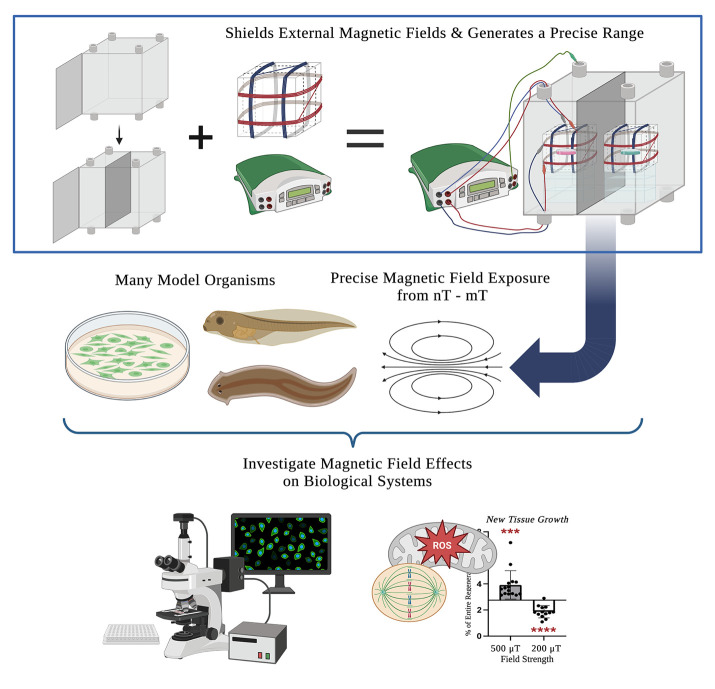
MagShield apparatus. This protocol offers a detailed guide on the construction and use of a static magnetic field exposure chamber (top right) for the investigation of magnetic field effects on biological processes. It consists of a mu-metal enclosure (top left), the design and calibration of 3-axial Helmholtz coils (top middle), and considerations for its use with aquatic (Xenopus embryos and larvae and adult planarians), cell culture model systems, and near-zero fields.
Background
Life evolved within the Earth’s natural geomagnetic field, which varies from 25 to 65 μT. However, in the modern environment, anthropogenic magnetic fields (MFs) generated by electronic devices and high-voltage power lines are now ubiquitous [1,2]. Exposures range from very low (e.g., 0.1–3 μT) for household appliances to extremely high (from 1.5 to 7 T) for clinical magnetic resonance imaging (MRI) devices [3–7]. With emerging technologies, new avenues for human exposure to non-ionizing radiation are continually introduced [8,9]. Additionally, the number of diagnostic and therapeutic uses for MFs is growing. The widely used MRI diagnostic relies on static MFs to provide detailed anatomical and physiological information [6,7]. Therapeutically, electromagnetic fields (EMFs) are used for pain management during rehabilitation and with musculoskeletal diseases such as neuropathy and fibromyalgia [10–14]. Research has demonstrated that exposure to even weak MFs can affect biological systems by altering free radical formation—believed to result from MF interactions with spin dynamics [15–21]. Weak MFs have been shown to change reactive oxygen species (ROS) signaling and alter cellular outcomes in vivo [19,22], and thus they represent a potential means to control host defense/immunological responses, regenerative stem cell proliferation, and cancer progression [23–28]. Despite increased interest in uncovering the underlying mechanisms, standardized methods for experimental exposure are lacking and few model systems have been used for in vivo studies (for a recent review, see [29]).
Using this protocol, the authors (a collaboration of engineers, developmental biologists, and geneticists) have successfully investigated MF effects in several different model systems. In vitro, we showed that exposure to static MFs of 0.5 μT and 600 μT MFs inhibited HT-1080 fibrosarcoma cell growth in culture, while 300 and 400 μT increased growth [16,17]. In vivo, we demonstrated that static weak MF exposure of regenerating planarians was able to manipulate stem cell proliferation and gene expression (where 200 μT decreased and 200 μT increased new tissue growth) via changes in superoxide accumulation after injury [19,22]. Our current efforts aim to investigate hypomagnetic field (nT) effects in the vertebrate model organism, Xenopus laevis. The use of a single standardized exposure protocol increases the ease of mechanistic comparisons across organisms and prevents confounding effects from the variance in MFs arising from incubators and standard laboratory equipment (hypothesized to contribute to experimental reproducibility issues even in non-MF experiments, which themselves could benefit from this type of controlled environment). This protocol provides step-by-step instructions on assembling a single 16 (w) × 16 (h) × 16 (d) in (40.64 cm × 40.64 cm × 40.64 cm) mu-metal MagShield apparatus for static MF exposure assays using 60 mm Petri dishes or 96-well plates, with a partition and two 3-axial Helmholtz coils to run controls and experiments concurrently. We focus here on the room temperature aquatic model systems Xenopus and planarians, as well as temperature-sensitive cell culture requiring placement in standard CO2 incubators with internal dimensions of 18.5 (w) × 23.9 (h) × 22.7 (d) in (46.99 cm × 60.71 cm × 57.66 cm). However, the apparatus could be easily adapted to other model systems (including zebrafish, C. elegans, Drosophila, and organoids), as well as extremely low–frequency EMF exposure.
Materials and reagents
Mu-metal enclosure (to block external MFs), ordered commercially using provided schematics (Mu-Shield Company, custom order). Enclosure inner dimensions: 16 (w) × 16 (d) × 16 (h) in (40.64 cm × 40.64 cm × 40.64 cm). Mu-metal thickness: 0.125 in (3.175 mm). See also Notes 1 and 2
-
Mu-metal partition (in order to run controls and experiments at different field strengths simultaneously):
Plexiglass sheet (Marketing Holders, ASIN: B08G5DD77N); dimensions: 16 (w) × 16 (h) in (same size as the side of mu-metal enclosure); sheet thickness: 1/8 in (3.175 mm)
Mu-metal foil with adhesive (PST on 1-side) (Magnetic Shield Corporation, item number: MUT002-8); foil length: 6 ft (1.8288 m); foil width: 8 in (20.32 cm) (need a total of 16 in wide but not sold wider than 8 in); foil thickness: 0.002 in (0.051 mm)
Two 3D printed Helmholtz coil base frames (STL file of 3D model provided as Supplemental File S1). Base frames were printed with 2.85 mm diameter PLA filament using an Ultimaker S3 printer with a 0.25 mm nozzle. Base frame outer dimensions: 14 cm × 14 cm × 14 cm. Distance between zip-tie anchors: 7 cm
Enameled copper wire for electrical applications, 17 AWG/1 lb (Emtel, model: EMTHERM200, ASIN: B08NW3YVL3). Wire length: 161 ft (49.0728 m). Wire thickness: 17 AWG diameter (1.15 mm)
Power leads (banana plug to alligator clip), 4 black and 4 red (for connecting the power supplies to the Helmholtz coils) 14 AWG (Zhenyu, item model number: ZY12091, ASIN: B0BPL4C29T). Lead silicone outside diameter: 3.5 mm. Lead length: 6 ft
-
Grounding lead (banana plug to alligator clip), 1 green, 18 AWG (DigiKey, Pomona Electronics, part number: 501-2514-ND, product number: EM1166-24-5#). Lead length: 2 ft
Note: The grounding lead does not have to be green, although we highly recommend that you use a separate color from the red/black power leads to clearly delineate your grounding lead.
Optional: For hypomagnetic field exposure, two small corrugated cardboard shipping boxes, 4 in × 4 in × 4 in (10.16 cm in all dimensions) for secondary mu-metal shielding (SUNLPH, ASIN: B09QCXPXY1)
Laboratory supplies
Safety glasses
Gloves
Scissors/metal shears
Ruler or tape measure
Zip-ties (wire management for Helmholtz coils)
Electrical tape (to secure lead connections)
Tape/adhesive (duct tape for the partition and laboratory labeling tape for wires is recommended)
Wire strippers
Wire cutters (if not already a function included with the wire strippers)
Sandpaper (may be needed when fitting Plexiglass partition)
-
Empty welled plates/Petri dishes (for positioning samples in the exact center of the Helmholtz coils)
Note: The width of the plasticware matters as they must fit in between the two rows of a Helmholtz coil pair (~6 cm). We recommend recycling used plasticware for positioning, such as 6/12/24-welled plates or 60 mm Petri dishes.
-
Empty pipette tip boxes/welled plates (for positioning the Helmholtz coils in the center of each chamber)
Notes:
The size of the plasticware does not matter for positioning the Helmholtz coils.
We recommend recycling used plasticware for positioning.
Optional: For cell culture/incubator placement, polytetrafluoroethylene (PTFE) tape (such as Teflon tape)
Equipment
-
Two DC power supplies, 300 W dual output, 30V/5A 30V/5A (Jameco, Mastech, part number: 301947, model: HY3005D-2-R)
Note: The dual output power supply is suitable for Helmholtz coils using x- and y-axes only. To use the z-axis as well, a triple output power supply (such as Mastech HY3005D-3-R, Jameco, part number: 301955) should be used.
DC milli/Gaussmeter (for experiments at 0–199 μT) (AlphaLab, Inc., model: MGM, sensor alignment: standard, bandwidth: 3 Hz)
DC Gaussmeter (for experiments at 200–1,000 μT) (AlphaLab, Inc., model: GM1-HS)
Procedure
This protocol requires a “pre-step” (Section A) of ordering the mu-metal enclosure. While waiting for this to arrive, the Helmholtz coils can be constructed (Section C), although this is not required. Once the mu-metal enclosure has arrived, the partition may be added (Section B). After all this is complete (Sections A–C), the MagShield apparatus can be assembled and calibrated (Section D) prior to use (Section E). The instructions are purposely comprehensive, despite the comparatively straightforward nature of constructing the apparatus. In particular, attention has been focused on providing explanations for biologists lacking engineering/physics backgrounds. Once all materials needed have been obtained, the entire apparatus can be constructed in a single day if desired. As an example, the hypomagnetic apparatus shown below was constructed by a team of mostly undergraduate students (with graduate student participation), and the initial test experiments began at the end of the day.
Critical: Read through the entire protocol before beginning.
-
Ordering the mu-metal enclosure (Figures 1-2 and Supplemental File S2)
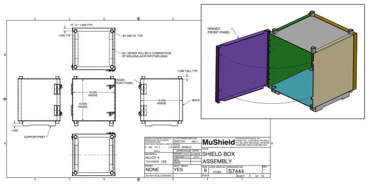
This protocol provides schematics (Figure 1 and Supplemental File S2) for constructing a 16 × 16 × 16 in enclosure (inside measurements) using mu-metal of 0.125 in thickness. The enclosure's features include accessibility ports, a latch system for the door, and support feet for stability. Most biology labs lack the necessary equipment for welding, and thus it is recommended to order the enclosure from a commercial company. See Notes 1 and 2.
-
We custom ordered the mu-metal enclosure (Figure 2) from The MuShield Company (Londonderry, NH) according to the provided schematics (although any company with the same capabilities will work).
Note: Mu-metal blocks external MFs, allowing researchers to precisely control experimental conditions.
Critical: Please note that construction times can be lengthy; for our supplier, the average delivery time was 12 weeks.
-
Adding the mu-metal partition (Figures 3–4)
-
It is important to always run a control concurrent with the experiment. Variations in local MF exposure of organisms prior to the assay could result in differences in experimental outcomes (and have in our experience). To run experiments simultaneously, a mu-metal-covered partition is created in the center of the mu-metal enclosure to produce two chambers that can have different MF strengths.
Note: You need the mu-metal enclosure (Section A) in order to complete this step.
-
Double-check the inner dimensions of the mu-metal enclosure (Figure 2A) and the dimensions of the Plexiglass sheet (Figure 3B–C), as dimensions may vary slightly during manufacturing. All dimensions should be 16 in (except thickness).
Notes:
The thickness of the Plexiglass is only required for the stability of the partition.
If the inner enclosure dimensions are not exactly 16 in, a Plexiglass sheet of the exact dimensions will be required. If the inner enclosure dimensions are only slightly smaller than 16 in, sandpaper may be used to reduce the Plexiglass sheet to the exact dimensions.
Caution: Plexiglass that is slightly (1 mm) larger in overall dimensions than the enclosure’s inner dimensions is preferable to Plexiglass that is slightly smaller. If the Plexiglass is larger, it can be sanded down to fit exactly, while Plexiglass that is smaller should not be used (as it will leave gaps in the shielding between the two chambers).
-
Cut the mu-metal foil (Figure 3A) by laying it out on a flat surface. Using a ruler/tape measure and a pencil, mark 16 in lengths on the mu-metal foil. Cut the foil along the marked lines using scissors or metal shears (Figure 3D). One partition should require four 16 in lengths (each 8 in wide), two for each side. Be precise as mu-metal foil is delicate and can easily become damaged.
Caution: You may wish to wear gloves to protect yourself from sharp edges.
-
Place the Plexiglass sheet on a flat surface and confirm mu-metal foil strips are the correct length. Peel off the backing paper to reveal the adhesive on the foil and cover the Plexiglass fully on both sides (Figure 3E). Cover any sharp edges from the foil with tape.
Notes:
If the edges of the Plexiglass are not smooth, sand them before attaching mu-metal foil.
If the mu-metal foil gets bent, the creases will be permanent. It can still be used, but then the dimensions will be off, and you will require more foil to cover the partition. While tiny, minor creases may be unavoidable, major creases as seen in Figure 3E should be avoided if possible.
Critical: The mu-metal foil must cover the entire surface of both sides, as any uncovered area will allow bleed through of the MF from one chamber into the other.
-
Place the foil-covered mu-metal partition in the middle of the enclosure so that it bisects the enclosure, making two equal-sized chambers (Figure 4A). Make sure the partition is securely in place.
Note: The fit should be tight enough that the partition will stay in place without being held.
-
For extra security, use tape (such as duct tape) to attach the partition to the enclosure at the top and bottom of both sides (Figure 4B–C).
Critical: It is important to avoid any gaps between the partition and the enclosure to ensure complete shielding between the two chambers.
Notes:
You will need to confirm that the MF generated in one chamber is not influencing the field strength in the other chamber. See step D9.
If there are no gaps but the partition does not provide full shielding between the two chambers (see section D), thicker mu-metal or more layers should be used. However, as a single layer of 3.175 mm mu-metal provides more than 99% attenuation, additional layers should not be necessary. See also Notes 1c and 6.
-
-
Constructing the Helmholtz coils (Figures 5–6 and Supplemental Files S1 and S3)
-
Download and print the 3D model (Figure 5A and Supplemental File S1) of the base frames for the 3-axial Helmholtz coils. You will need to print two bases (one for controls and one for experiments). The provided STL file produces a base frame of 14 (w) × 14 (d) × 14 (h) cm, which is suitable for assays using a single 60 mm (or 35 mm) Petri dish or 96-well plate.
Note: The breakaway support structures connecting the zip-tie anchors are shown still attached in Figure 5B and removed in Figure 5C. Make sure these supports are removed prior to winding.
Note: Only two axes (x- and y-axis) are required for this protocol.
-
The base frame, made from non-conducting material [polylactic acid (PLA) filament], allows for three Helmholtz coil pairs (one pair each for the x, y, and z axes, Figure 5D). For this protocol, only the x and y pairs are used. Each coil pair is comprised of two rows (left and right) on the same axis (arrows in Figure 5D) that are positioned at a specific distance apart in parallel orientation. The 3D model provided includes zip-tie anchors (Figure 5C) for both correct positioning of coil rows and wire management. For this size base frame, the correct distance between anchors is 7 cm. Each face/side of the base frame has eight zip-tie anchors: four for each axis (the axes are perpendicular to each other).
Critical: The space between the two rows of each coil pair must be separated by a distance (h) equal to the radius (R) of the coil.
Note: The zip-tie anchors in the provided 3D model file are positioned exactly at this distance.
-
Wind one coil pair onto the first side (axis) of one base frame.
-
Temporarily secure the copper wire to the base frame, centered over the appropriate zip-tie, with a small piece of tape/adhesive. Leave approximately 4 in (~10 cm) of wire free at the beginning for attaching to the power supply leads (arrow in Figure 6A).
Critical: Make sure to always keep your wire centered over the zip-tie anchor so that the final distance of the two rows will remain the correct distance apart.
Note: It does not matter whether you start with the left or right row of the coil pair.
-
Wrap the copper wire completely around the base frame for one full revolution, until you are back where you started. This is considered one winding. Continue until you reach a total of 50 windings for the first row of that coil pair.
Critical: Make sure your wire stays centered over the appropriate zip-tie anchors on each face of the base frame.
-
Cross your wire to the other side of the coil pair (asterisk in Figure 6B) to begin the second row/coil of that pair. Both rows of each coil pair are made from one continuous length of copper wire.
Critical: The winding for the second coil needs to follow the same direction of winding as the previous one.
Continue until you reach 50 windings for the second row of that coil pair.
-
Secure the end of the wire to the frame temporarily with a small piece of tape/adhesive to keep it in place. Cut the wire, leaving approximately 4 in (~10 cm) of wire free at the end (in addition to the 50 windings) to attach to the power supply leads (Figure 6A).
Note: The tape secures the wire until all coil pairs for that base frame are finished. Do not attach with zip-ties (as seen in Figure 6) until all coil pairs are wound.
Critical: Make sure that, when finished, the two rows of the coil pair are parallel to each other and centered over their respective zip-tie anchors.
-
Repeat steps C3a–e for the two other coil pairs on that same base frame.
Note: Only two perpendicular axes (x- and y-axis) are needed for this protocol. Winding the third coil pair for the z-axis is optional.
Use wire strippers to remove the insulation from both ends of the copper wire (arrowhead in Figure 6C) of each coil pair. Make sure the wire ends are clean and exposed.
-
Secure each coil row to the base frame using zip-ties through each zip-tie anchor, cutting off the unused “tail” of each zip-tie (Figure 6D) and removing any tape that was temporarily holding the wire to the frame.
Note: We recommend that on the two “open” faces of the base frame, you zip-tie the middle of each coil row (as seen at the top of Figure 6D) for stability and to ensure proper spacing is maintained.
Repeat the entire process (C3a–h) for the other base frame.
-
-
-
Assembly and calibration of the MagShield apparatus (Figures 7–9)
-
Place the mu-metal enclosure on a stable, level surface that also has enough room for the power supplies.
Note: This should be the final placement for the apparatus.
Position the power supplies to one side of the enclosure. Each power supply will provide current to a single Helmholtz coil (either the control or the experimental). A single power supply connects to one Helmholtz coil via four leads: one positive (red) and one negative (black) lead will connect to each coil pair on both x and y axes.
-
Connect the leads to the Helmholtz coils (Figure 7).
Caution: Steps D3–7 should be done without power to the Helmholtz coil to ensure safety.
-
Take one Helmholtz coil and attach the alligator clip of the red lead to one of the exposed wire ends of a coil pair (arrow in Figure 7A). Attach the black lead to the other end of the wire of that same coil pair (which will be on the other row).
Note: Each coil pair forms a circuit with one positive and one negative input.
-
Secure the alligator clips to each wire end using electrical tape (arrowhead in Figure 7A).
Critical: Ensure the connections are secure and insulated to prevent short circuits.
Tape the red and black leads together (for lead management/organization) as shown in Figure 7D. Label the banana plug ends of each lead as either x- or y-axis based on that coil pair’s orientation (refer to the diagram in Figure 5D). General laboratory labeling tape can be used.
With another set of red/black leads, repeat steps D3a–c for the remaining coil pair on that same Helmholtz coil.
Repeat the entire process (D3a–d) for the other Helmholtz coil.
-
-
Position the Helmholtz coils in the enclosure.
In each chamber, create a platform using a stack of empty plastic pipette tip boxes or non-conductive welled plates that will position one Helmholtz coil exactly in the center of that chamber (Figure 7B).
When placed on the platform, the center of the Helmholtz coil should correspond to the center of the chamber. This is required for the uniformity of the MF exposure.
-
Tape the final stack of tip boxes/plates together for platform stability.
Note: Alternately, a separate stage using a non-conducting material such as cardboard or plastic can be designed if more stability for the Helmholtz coil is needed/desired.
-
Connect the Helmholtz coils to the power supplies (Figure 8). Ensure the power supplies are turned off and unplugged before starting the process.
-
After each Helmholtz coil (wound base frame) is placed on its platform, feed all the leads from one Helmholtz coil through the most convenient access port. Leads can be fed through either the top (Figure 8A) or bottom (Figure 8B–C) ports.
Critical: It is imperative to ensure that the Helmholtz coils themselves do not make contact with the mu-metal of the enclosure's sides.
-
The four leads from a single Helmholtz coil connect to a single power supply. Each power supply has two groups of terminals, one group for each axis of a single Helmholtz coil.
Note: If using the optional z-axis, there will be six leads from each Helmholtz coil that will all connect to a single power supply with three terminals.
Identify one set of positive (red) and negative (black) terminals on one power supply and attach the corresponding colored leads (via the banana plugs) from one axis of one Helmholtz coil (Figure 8D).
Attach the other set of leads for the remaining axis on that base frame to the other set of terminals on that same power supply.
Repeat steps D5a–d with the other power supply and the remaining Helmholtz coil (wound base frame).
-
Ground the MagShield apparatus by attaching the green lead to any of the green terminals on either power supply via the banana plug end and then attaching the alligator clip to one of the unused access ports on the mu-metal enclosure (asterisk in Figure 8E). Only one ground lead is required.
Create two raised stages using stacks of empty Petri dishes or welled plates that will position your samples exactly in the center of each Helmholtz coil (Figure 7C). The raised stage can be taped together for stability.
-
Calibrate the MagShield apparatus.
-
Plug in and turn on the power supplies and determine your working voltage and current settings by using the milli/Gaussmeter to measure the MF produced at the center of the Helmholtz coil. Tape the probe end to the stage for accurate readings (Figure 8F).
Caution: Monitor the power supplies for any unusual behavior or overheating. If any issues arise, turn off the power supply immediately.
Critical: The orientation of the meter’s probe is crucial for an accurate reading, as the meter will still display an (incorrect) reading in the wrong orientation. Consult the user manual of the milli/Gaussmeter for guidance on proper usage for your meter.
Critical: If your meter is not correctly calibrated, then your MagShield apparatus will not be either. Make sure that your milli/Gaussmeter has a current calibration record/certificate and that routine maintenance, including recalibration, is performed as directed by the manufacturer. Most manufacturers recommend at least annual meter calibration.
-
The first step when measuring the field strength of the coils needs to be a measurement of each coil axis separately, while the other coils are not connected to the power supply. For example, supply power to the x-axis coil pair only and record the field strength produced.
Note: The probe should remain taped to the stage at the center of the Helmholtz coil (where your experiments will be placed) for all field strength measurements.
Change the power supply settings (according to manufacture guidelines) until you record a field strength at (or as close as possible) to your desired MF strength.
-
Repeat steps D8b–c for the other axis coil pair (such as the y-axis).
Critical: The orientation of the meter’s probe will need to be changed with each different axis; refer to your specific probe’s user manual for proper orientation.
Note: If using all three axes, repeat for the y-axis coil pair as well.
After initial measurements of each individual coil axis, measure the field strength produced by the Helmholtz coil (wound base frame) by supplying power to all axes simultaneously. Measure the field strength recorded when the probe is in each orientation specific to each axis. For example, with power to both x- and y-axes, record the MF strength with the probe in both the x and then y orientations. There should not be any significant differences; however, it is important to confirm the field strength when all the coils are connected.
Change the power supply settings for each axis until you record your desired field strength for the entire Helmholtz coil (i.e., with power to all axes).
Repeat steps D8a–f for both your control and your experimental chambers until you record your desired MF strength. Document your specific power supply settings for future reference.
-
To confirm that the MF generated in one chamber is not influencing the field strength generated in the other chamber, take measurements with the milli/Gaussmeter of the ambient field strength in one chamber (without power) while simultaneously increasing the field strength in the other chamber (with power). There should be no fluctuations of field strength recorded, indicating a lack of bleed through.
Once the MagShield apparatus is completed and calibrated (Figure 9 and Supplemental File S3), we recommend performing an initial trial run of both Helmholtz coils at the desired field strengths without samples lasting for the total time of your assay. During this trial run, multiple field strength and temperature checks should be conducted (at the center of each Helmholtz coil) to ensure that environmental and exposure conditions remain stable.
-
-
General basic operation of the MagShield apparatus
Note: These general instructions are for room-temperature aquatic model systems where the organisms are free swimming/moving (such as planarians). This requires the use of both the x-axis and y-axis coil pairs to ensure a uniform field regardless of the animal’s position in the dish.
Inspect the wires, leads, and connections, to ensure they are in good condition and free from damage/wear.
-
Carefully turn on the power supplies, ensuring that the output is at your predetermined settings (see Section D).
Caution: Monitor the power supplies for any unusual behavior or overheating. If any issues arise, turn off the power supply immediately.
Critical: Ensure that there are no loose connections, exposed wires, or other safety hazards.
-
Use the milli/Gaussmeter to confirm your field strengths at the beginning of each experiment for both coils. Tape the probe end to the top of the stage to get accurate measurements.
Critical: You should repeat all steps of Section D, Step 8 each time you measure field strength.
Note: Controls are typically run at or near 45 μT, as Earth normally averages 25–65 μT. It is recommended to designate one power supply/Helmholtz coil set as your control set.
-
Watch for any changes in current/voltage in the first few minutes, ensuring that they remain stable.
Note: Fluctuations in current/voltage suggest a loose connection.
-
Place your samples on the Helmholtz coil stage. Samples will only be exposed to a uniform field if they are placed in the center of the Helmholtz coil. There are limits to the number of samples that can be accommodated. Only one 60 mm Petri dish or 96-well plate should be placed in each chamber.
Caution: The power supply should be disconnected and off for the safety of the person placing the sample in the center of the Helmholtz coil.
Critical: Do not place samples in the outer wells of a 96-well plate, as their field strength exposure will not be comparable to those in the center.
-
At the end of each experiment, always confirm with the milli/Gaussmeter that the field strengths of each Helmholtz coil have remained the same.
Critical: Trials where field strengths did not remain constant should not be used and suggest a problem with the power supply or the connections between the power supply and the coils (the leads).
-
Make sure to turn off both power supplies at the end of each experiment.
Caution: Always exercise caution when working with electrical equipment and follow safety guidelines and manufacturer's instructions.
-
Modifications for cell culture (Figure 10)
Note: These modifications are for environmentally controlled model systems where the MagShield apparatus needs to be housed inside an incubator. For organisms that are not freely swimming, such as cell culture, the use of a single axis is required. In our experiments with HT-1080 cells, we observed significant effects on cell growth and mitochondrial calcium levels when the MFs were perpendicular to the cell culture flask compared to when they were parallel (see Validation, Section B). As a result, we chose to only utilize the y-axis of the Helmholtz coils in some of our experiments.
The provided mu-metal enclosure schematics are designed so that the MagShield apparatus will fit inside standard CO2 incubators with internal dimensions of 18.5 (w) × 23.9 (h) × 22.7 (d) in (Figure 10). Most standard incubators come with ports for access to the outside.
The length of the leads may need to be changed so that they can extend through the incubator port to the power supplies to the Helmholtz coils. We used test leads with banana-to-banana connectors that are 60 in long to extend through the incubator port to connect to the power supplies for the Helmholtz coils.
-
Cell culture experiments will typically require the use of different sensors to monitor the environmental conditions inside the MagShield apparatus.
For example, it is essential for cell culture experiments that there is a CO2 monitor to verify proper air circulation (even though vents are designed into the enclosure).
This protocol is adaptable to accommodate various sensor types (temperature, CO2, humidity, etc.).
We addressed the need for cable access by opening a hole in the silicon plug of the port, which was sized precisely to accommodate the leads. Furthermore, we took precautionary measures by wrapping the leads with Teflon tape to prevent any gas leaks from the incubator. This approach ensured that the leads could enter the incubator without compromising its integrity, thereby allowing for the safe and effective operation of the MagShield apparatus within the incubator environment.
-
Modifications for hypomagnetic fields (Figure 11 and Supplemental File S4)
Note: These modifications are for experiments testing the effects of near-zero MF exposure. An additional mu-metal-covered container is required.
For experiments in hypomagnetic, “near-zero” fields (< ~10 μT), increased mu-metal protection from surrounding MFs is required, necessitating the use of an additional mu-metal-covered container inside the MagShield apparatus for experiments.
-
Only a single power supply and Helmholtz coil (wound base frame) is required for near-zero experiments, which is used for controls.
Note: It is possible to run near-zero assays without the use of any Helmholtz coils, where controls are placed in “normal” environmental conditions.
Caution: Due to the high variability of environmental conditions, we strongly recommend the use of the MagShield apparatus to shield external MF and a Helmholtz coil to generate an average Earth normal MF (45 µT) for all control conditions.
-
Cover a 4 in × 4 in × 4 in cardboard shipping box with mu-metal foil for secondary containment (red arrow in Figure 11A).
Critical: Make sure that all surfaces, including the lid, are covered in mu-metal to provide a complete secondary MF barrier.
Caution: The edges of the mu-metal foil are sharp. The sharp edges of the mu-covered container can be covered in tape (Figure 11B) to prevent injuries.
-
Alternately, since Helmholtz coils are not needed for hypomagnetic experimental conditions, larger secondary containers can be used, such as the 3D-printed secondary containment options shown in Supplemental File S4.
Critical: Make sure that all surfaces of the non-conductive container, including the lid and the inside, are covered in mu-metal foil to provide a complete secondary MF barrier, using tape to cover any sharp edges from the foil.
Place the smaller mu-metal container in the experimental chamber of the MagShield apparatus in place of the experimental Helmholtz coil (Figure 11C).
-
Using the milli/Gaussmeter, validate that in the experimental chamber the MF is at the desired near-zero field strength inside the smaller mu-metal container (when inside the MagShield apparatus). Then, validate that in the control chamber the control MF inside the Helmholtz coil is also accurate.
Note: Even though no Helmholtz coil is needed, you should still record the field strength in the experimental chamber with the milli/Gaussmeter probe in the correct orientation for all three axes (x, y, and z) to ensure that the field is truly near zero.
Figure 1. Schematic for MagShield apparatus enclosure.
Schematic diagrams for constructing the 16 × 16 × 16 in enclosure out of 0.125 in thickness mu-metal. See Supplemental File S2 for complete details.
Figure 2. Mu-metal enclosure.
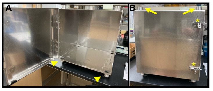
As unpacked directly from the supplier, before the addition of the partition. (A) Inside. (B) Front outside. Note the door latches (asterisks), access ports at the top (arrows), and the access ports at the bottom (arrowheads).
Figure 3. Constructing the mu-metal partition.
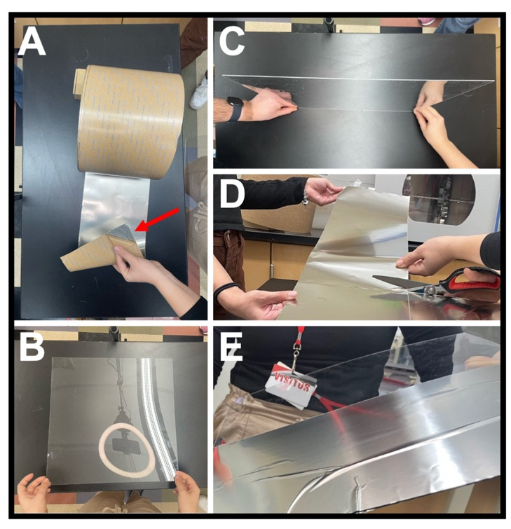
(A) Mu-metal foil showing a corner where the adhesive packing is peeled off (arrow). (B) Plexiglass sheet. (C) View of Plexiglass sheet thickness 1/8 in (3.175 mm). (D) Cutting the mu-metal foil with adhesive backing into 16 in lengths. (E) First 16 in strip of foil attached to half of the Plexiglass sheet.
Figure 4. Installing the mu-metal partition.
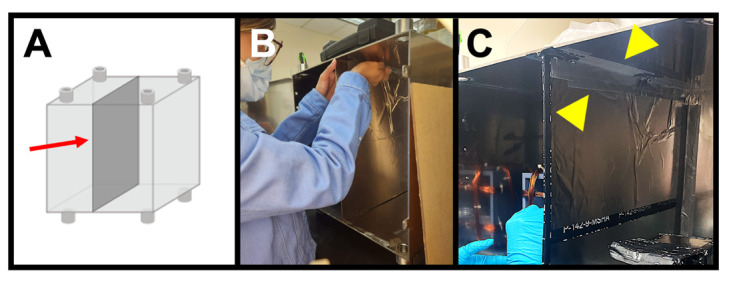
(A) Correct placement (arrow) of the foil-covered Plexiglass sheet, bisecting the mu-metal enclosure. (B) Taping the partition to the enclosure for extra stability. (C) Final installation of the mu-metal partition, showing the tape (arrowheads) connecting the partition to the enclosure.
Figure 5. Helmholtz coil anatomy.
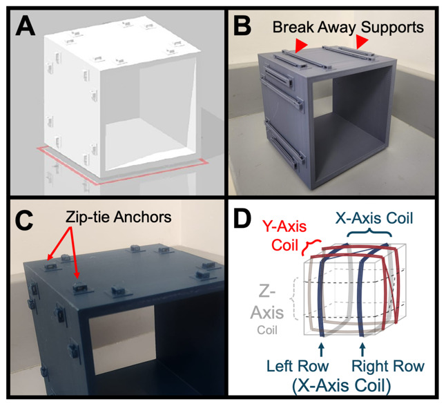
(A) 3D model of the base frame. (B) Actual 3D printed base frame, with breakaway supports (arrowheads) still attached. (C) Close-up of the 3D printed base frame with breakaway supports removed. Note the raised zip-tie anchors (arrows) for correct positioning of coil rows and wire management. (D) Diagram of 3-axial Helmholtz coil showing the three coil pairs for the three axes (x in blue, y in red, and z in grey).
Figure 6. Winding the coils.
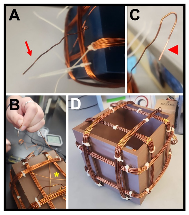
(A) Free end of the copper wire (arrow) for one coil, where 4 in (~10 cm) of wire is left unwound at each end for attaching to the power supply. (B) View of one face of a completed coil, showing the crossing of the copper wire (asterisk) between the left and right coil pairs. (C) Free end of one coil, showing the stripped insulation (arrowhead) required for a strong connection to the power supply lead. (D) Completed Helmholtz coil with three coil pairs (x, y, and z) that have been zip-tied (white clasps) to the base frame via the anchors and had the zip-tie “tails” cut off.
Figure 7. Placement of the coils, samples, and leads.
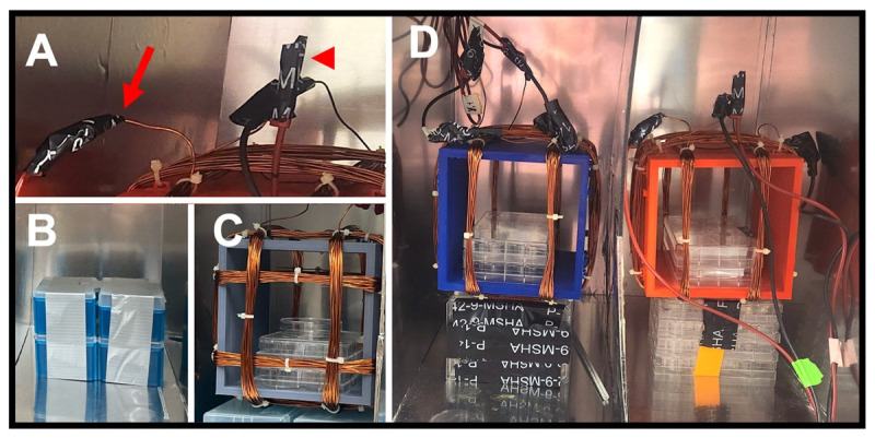
(A) The alligator clip end of a red lead is attached to the exposed end of one coil pair (arrow). The alligator clip of a black lead is attached to the other end of that same wire (middle of image). To ensure a good connection, secure the clip to the wire with electrical tape (arrowhead). (B) A taped stack of used pipette tip boxes is used to position the Helmholtz coil in the center of each partition. (C) A complete Helmholtz coil with a stack of used plasticware (welled plates) to position the samples (Petri dish) in the center of the coil base frame. (D) Final positioning of both Helmholtz coils, one in each partition. Note in the lower-right corner where a pair of red and black leads clipped to each end of a single coil pair have been taped together (green tape).
Figure 8. Connecting to the power source.
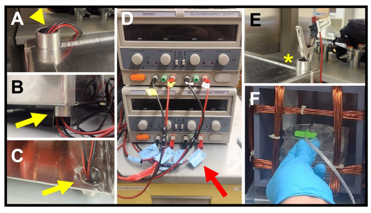
(A) Leads from a Helmholtz coil fed through an upper access port (arrowhead). (B–C) Views of a set of leads fed through a lower access port (yellow arrows), shown from the outside (B) and the inside (C) of the enclosure. (D) Power supplies with attached leads. Red arrow shows axis labeling of each lead. (E) Alligator clip end of ground lead (asterisk) attached to an upper port on the enclosure. (F) Probe end of a milli/Gaussmeter, taped to the stage in the correct orientation for that make of probe, during a test of field strength.
Figure 9. Completed MagShield apparatus.
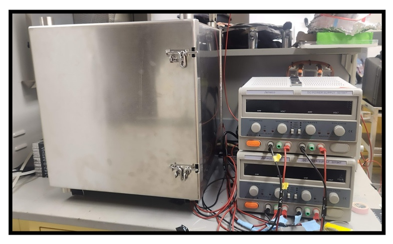
Shown with enclosure safety latches securing the door shut and power supplies positioned next to the mu-metal enclosure so that the leads can reach the coils inside.
Figure 10. Modified MagShield setup for cell culture.
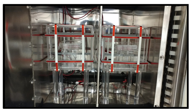
View of MagShield apparatus inside a carbon dioxide (CO2) incubator used for cell culture, as previously reported [17]. This modification is required to maintain specific temperature, humidity, and gas composition needed to support the growth of cells in culture. Modifications include additional environmental sensors and considerations to prevent gas leaks while accommodating lead access to the power supplies.
Figure 11. Hypomagnetic field exposure setup.
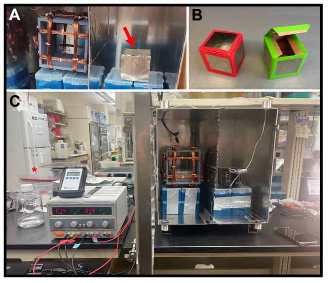
(A) Interior of MagShield apparatus showing a Helmholtz coil in the left partition for Earth-normal controls, and an additional mu-metal-covered container for “near-zero” (< ~10 μT) hypomagnetic fields in the right partition (red arrow). (B) Mu-metal covered near-zero containers shown with tape covering sharp edges. (C) Photo of the hypomagnetic field exposure setup, with a single power supply and Helmholtz coil for controls, and additional mu-metal container for near-zero experiments.
Validation of protocol
This protocol or parts of it has been used and validated in the following research articles:
Van Huizen, et al. [22]. Weak magnetic fields alter stem cell–mediated growth. Science Advances. 5: eaau7201. doi:10.1126/sciadv.aau7201.
Gurhan et al. [17] Effects induced by a weak static magnetic field of different intensities on HT-1080 fibrosarcoma cells. Bioelectromagnetics 42(3): 212–223. doi: 10.1002/bem.22332.
Gurhan et al. [16]. Impact of weak radiofrequency and static magnetic fields on key signaling molecules, intracellular pH, membrane potential, and cell growth in HT-1080 fibrosarcoma cells. Scientific Reports. 13, 14223. https://doi.org/10.1038/s41598-023-41167-5.
Gurhan et al. [15] Weak radiofrequency field effects on chemical parameters that characterize oxidative stress in human fibrosarcoma and fibroblast cells. Biomolecules. 13(7): 1112. https://doi.org/10.3390/biom13071112.
Kinsey et al. [19]. Weak magnetic fields modulate superoxide to control planarian regeneration. Frontiers in Physics. 10: 1–20. https://doi.org/10.3389/fphy.2022.1086809.
-
Planarian regeneration experiments (Figure 12)
Amputation scheme (Figure 12A): Previously, we investigated static MF effects on planarian regeneration only for trunk fragments (with heads and tails removed) that have two amputation planes (one above and one below the pharynx/feeding tube) [19,22]. To determine the effects on fragments with a single amputation plane, we investigated three other fragment types. Schmidtea mediterranea (5–7 mm in size) were amputated just above the pharynx to generate both a) head fragments that will undergo posterior regeneration of both pharynx and tail, and b) posterior fragments (which include both the pharynx and tail) that will regenerate a new head. Additionally, we amputated animals just below the pharynx to produce c) tail fragments that will undergo anterior regeneration of both a new head and pharynx.
Our previous studies found that weak static MF effects were dependent on field strength, with increased stem cell–mediated regeneration peaking at 500 μT and decreased regeneration peaking at 200 μT. For our three new fragment types, regenerates were exposed to static MFs at either control (45 μT), 200 μT, or 500 μT field strengths. MF exposure occurred from within 5 min of amputation until Day 3 of regeneration, when blastema (new tissue) growth at the wound site was analyzed for all fragment types (Figure 12B–E). Blastema size was measured as a percentage of total regenerate size, to account for worms/fragments of different sizes.
We found that compared to controls, 500 μT static MF exposure resulted in blastemas that were significantly larger for all three fragment types (Figure 12E): head fragments (500 µT, p = 0.0255), posterior fragments (500 µT, p = 0.000975), and tail fragments (500 µT, p = 0.000596). Similarly, our results demonstrated that 200 µT exposure produced regenerates with significantly inhibited regeneration in all fragment types (Figure 12E): head fragments (200 µT, p = 0.000465), posterior fragments (200 µT, p = 9.65E-06), and tail fragments (200 µT, p = 4.727E-05).
Together, these data indicate that similar to fragments with two amputation planes, the regeneration of planarians with a single wound site can also be modulated by weak static MF exposure. Furthermore, MF regulation of stem cell–mediated regeneration, in a field strength-dependent manner, can both increase and decrease new tissue growth regardless of the number of new tissues/organs that must be regenerated. Additionally, these data suggest that MF effects on new tissue growth are consistent regardless of the level of the injury along the anterior-posterior axis.
Statistics and quantification: Specific sample sizes (n) that correspond to the total number of worms across all replicates and the number of independent replicates or trials (N) were as follows. For 45 µT exposures: n = 12, N = 4 for head fragments; n = 31, N = 4 for posterior fragments; and n = 15, N = 2 for tail fragments. For 500 µT exposures: n = 12, N = 2 for head fragments; n = 15, N = 2 for posterior fragments; and n = 10, N = 1 for tail fragments. For 200 µT exposures: n = 13, N = 2 for both head fragments and posterior fragments; and n = 5, N = 1 for tail fragments. The magnetic lasso tool in Photoshop (Adobe) was used to generate total pixel counts of the blastema (white tissue at the wound site) and the total regeneration (entire worm including blastema). Blastema size is reported as a percentage of total body size: (blastema size/body size) × 100. Significance was calculated using a two-tailed Student’s t-test with unequal variance (Microsoft Excel or GraphPad Prism 10), where p < 0.05 was considered statistically significant. Each experimental group was normalized against its corresponding control group, which was maintained at 45 µT (average Earth normal).
-
Cell culture experiments (Figure 13)
Cell growth (Figure 13A): The impact of static MF exposure on the growth rates of HT-1080 cells fibrosarcoma cells over a four-day period, ranging from 0.5 to 600 µT was analyzed. Notably, growth rates showed an initial increase from 0.5 to 400 µT, followed by a decline at 600 µT. Growth rates at 0.5 and 600 µT were significantly lower by 9% (p < 0.001) compared with the control group at 45 µT (average Earth normal); conversely, at 300 and 400 µT, growth rates exceeded controls by 23% (p < 0.001) and 28% (p < 0.001), respectively.
Hydrogen peroxide (H2O2) levels (Figure 13B): Amplex Red reagent assay was used to measure the production of H2O2 in HT‐1080 fibrosarcoma cells. Concentrations of H2O2 exhibited a non-linear response corresponding to the intensity of the applied MF. Specifically, at 100, 200, 500, and 600 µT, the concentration of H2O2 surpassed that of the control group significantly (p < 0.001), indicating an increase. Conversely, at 300 µT the concentration was lower than controls (p < 0.05), suggesting a decrease in H2O2 concentration.
Mitochondrial calcium levels (Figure 13C): The Rhod‐2 AM probe was used to determine mitochondrial Ca2+ level in HT‐1080 human fibrosarcoma cells. Exposure to static MFs lead to a notable increase in mitochondrial calcium concentration as MF intensity rose. Significant disparities were evident at 200 µT (p < 0.05) and across the range of 300–600 µT (p < 0.001), as compared with the control group.
Statistics: The total sample count is denoted as “n” (corresponding to the total number of samples across all replicates), while the number of independent replicates or trials is denoted as “N” (see Figure 13 legend). Statistics were conducted using Origin Pro 2017 Statistical Package (OriginLab, Northampton, MA). Differences in cell growth rates and fluorescence were deemed statistically significant when p < 0.05. For comparisons between two independent samples, Student's t-test was used, while one-way analysis of variance (ANOVA) with Tukey post-hoc was used to contrast the means of multiple independent samples. Each experimental group was normalized against its corresponding control group, maintained at 45 µT.
-
Xenopus hypomagnetic field experiments (Figure 14)
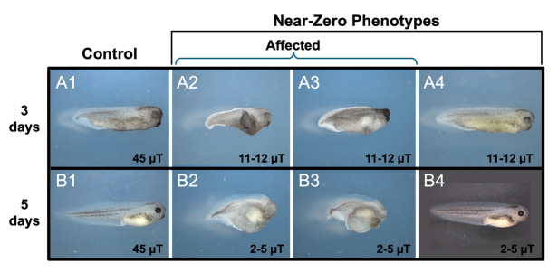
To investigate static MF effects on the development of vertebrate embryos, Xenopus laevis were exposed to either control (45 μT) or hypomagnetic field strengths (< ~10 μT) starting from the two-cell stage.
Two trials were performed as part of our initial runs. For both, “n” corresponds to the total number of animals across all replicates, while “N” is the number of independent replicates.
For trial 1 (n = 28 for control and n = 29 for experimental animals, N = 1 for each), the hypomagnetic field measured from 11 to 12 μT and embryo morphology was assessed at three days of development (Figure 14A). While all control animals displayed normal development, 2/29 experimental animals displayed stunted growth.
For trial 2 (n = 30, N = 1 for both controls and experimental animals), the hypomagnetic field measured from 2–5 μT and embryo morphology was assessed at 5 days of development (Figure 14B). Similar to our previous trial run, all control animals developed normally while 3/30 experimental animals had stunted growth.
These preliminary data are promising and suggest investigation of hypomagnetic fields on vertebrate development is an area for exploration.
Figure 12. Effects of static magnetic fields on planarian regeneration.
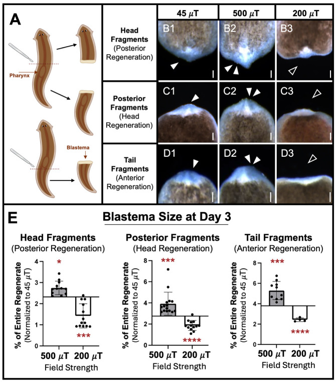
Regenerating fragments analyzed for blastema size (new tissue growth, visualized as the white region at the wound site) after three days of exposure to 500 µT (activating), 200 µT (inhibiting), or 45 µT (control) field strengths, using the MagShield apparatus as described in this protocol at 20 °C (room temperature). (A) Diagram of cuts. Adult planarians were transected by scalpel at one of two different amputation planes (dotted red lines), one above and the other below the pharynx (feeding tube), producing three different fragment types. (B) Head fragments, regenerating their pharynx and tail. (C) Posterior fragments, regenerating their head. (D) Tail fragments, regenerating their pharynx and head. (E) Quantification of B–D. Anterior is up. Single solid arrows: control blastema size. Double solid arrows: increased tissue growth. Empty arrows: inhibited tissue growth. Scale bars = 100 µm. n ≥ 5. Error bars = SEM. * p < 0.05, *** p < 0.001, **** p < 0.0001.
Figure 13. Effects of static magnetic field intensity on fibrosarcoma cells.
HT-1080 cell line exposed to a range of 0.5–600 µT static MFs, with 45 µT as controls (“C” bar on graphs), using the modified MagShield apparatus for cell culture in a 37 °C CO2 incubator. (A) Effects on cell growth. Cell growth rates expressed as a function of static MF exposure (mean ± SD) with the fields perpendicular to the flask bottom; n = 12, N = 3 for each group. (B) Effects on hydrogen peroxide (H2O2) levels. H2O2 concentrations as a function of static MF exposure (mean ± SD); n = 63, N = 3 for each group. (C) Effects on mitochondrial calcium (Ca2+) levels. Mitochondrial Ca2+ concentrations as a function of static MF exposure (mean ± SD) for fields oriented at 90° with respect to the plane of the cell flask bottom; n = 63, N = 3 for each group. * p < 0.05, ** p < 0.01, and *** p < 0.001. Error bars = standard deviation (SD).
Figure 14. Preliminary developmental phenotypes from hypomagnetic field exposure of Xenopus larvae.
Embryos exposed to either 45 µT (controls) or near-zero static MFs using the modified MagShield apparatus for hypomagnetic fields at 20 °C (room temperature). (A) Trial run 1: phenotypes at 3 days of development. (A1) Controls, phenotype n = 28/28. (A2-3) Near-zero affected phenotypes at 11–12 μT: Stunted growth with defects in anterior structures and anterior-posterior (AP) axis formation; n = 2/29. (A4) Representative phenotype of 11–12 μT animals with normal appearance. (B) Trial run 2: phenotypes at 5 days of development. (B1) Controls, phenotype n = 30/30. (B2-3) Near-zero affected phenotypes at 2–5 μT: Continued stunted growth with defects in anterior structures and AP axis formation; n = 3/30. (B4) Representative phenotype of 2–5 μT animals with normal appearance. Anterior is to the right and dorsal is up.
General notes and troubleshooting
General notes
-
Magnetic field shielding
The mu-metal suggested in this protocol is not the only material that can be used to shield experiments from MFs. Any high magnetic permeability material (such as ferromagnetic metals) can be used to redirect surrounding MFs around and away from your experiments.
While there are companies other than The MuShield Company that have similar proprietary alloys for magnetic shielding, materials such as soft iron can be used if a less expensive option is desired.
The amount of shielding is directly linked to the thickness of the material. For instance, if using soft iron, the thickness of the enclosure would need to be substantially greater. See also Note 6.
-
Considering effects from radiofrequencies (RF)
Our recent data suggest that RF fields from wireless sources (such as cell phones and radio stations) can also cause biological effects [15,16] and could represent a confounding variable.
To protect experiments from RF interference, wrap an extra layer of shielding completely covering the mu-metal enclosure in the form of aluminum foil, which reduces exposure by 15–20 dB.
-
Designing a MagShield apparatus of different dimensions
-
Start the design process by defining the size of the coils needed. The size of your coils is closely tied to the dimensions of your sample plates, Petri dishes, or containers. This protocol is tailored for samples in 60 mm Petri dishes or 96-well plates.
Note: Reference [29] provides designs for many variations of Helmholtz coils.
There are limits to the number of samples that can be accommodated and maintain a uniform field. In general, only one 60 mm dish or welled plate should be placed in each partition, with one control plate in one partition and one experimental plate in the other.
-
Middle-positioned wells of 96-well plates are ideal for this setup but do not put samples in the outer wells as the field strengths will not be comparable (i.e., not uniform across the entire plate).
Note: If wanting to change the dimensions of the Helmholtz coils, please note that the design and wire winding process for Helmholtz coils can be quite complex and the specifics can vary greatly depending on your application requirements. It is essential to take the necessary safety precautions and, if needed, consult with experts in electromagnetics or coil design to ensure your Helmholtz coils function as intended.
-
-
Coil considerations and relationship to field uniformity and temperature
Changing Helmholtz coil size will affect the MF produced, as the MF is inversely related to radius. Coils with a larger radius would result in a smaller MF and vice versa, as long as the current remains the same.
If not 3D printing your base frames, ensure you have frames made from non-conductive material, such as PVC or wood. These frames should be shaped like circles or squares, depending on your design preference, and sized appropriately for the coils.
Determine the desired number of windings for each coil. This protocol used 50 windings tested with fields up to 900 µT. This depends on your specific application and the MF strength you want to generate. You can use mathematical formulas or MF simulation software for precise calculations.
The strength of the MF you intend to work with will affect the amount of heat that is produced. Higher field strengths generate more heat, which must be factored into your setup. In addition, any change to the power supplies used, as well as the thickness of the copper wire and the number of windings, will also affect the amount of heat produced.
-
Relationship of field strength to temperature
The power supplies recommended in this protocol can accommodate MF strengths ranging from near-zero to 1 mT without causing significant temperature fluctuations (see Supplemental File S5 for temperature fluctuation data at various MF strengths). In case higher field strengths are desired, potential modification options to mitigate any associated temperature increases include:
Increased number of windings: By increasing the number of windings in each row of a Helmholtz coil pair, the same MF strength can be achieved with a lower current, reducing heat generation.
Temperature-resistant coating: Applying a temperature-resistant coating to the copper wire/coils can help dissipate heat more effectively, minimizing potential temperature increases in the chamber.
Thicker copper wire: Using thicker wire for your coils can reduce the resistance and thus the heat generated. This can also help in maintaining a stable temperature within the experimental setup.
Note: Mu-metal barriers are typically custom-made for specific applications and must be designed according to the specific requirements of the magnetic shielding. If you are dealing with high-strength MFs or complex shielding requirements the barrier will need to be modified to be thicker or more layers may be necessary.
-
Relationship of Mu-metal thickness to shielding capabilities
The thickness of mu-metal plays a pivotal role in determining its shielding capabilities. Mu-metal barriers are typically custom-made to meet specific shielding requirements, especially for high-strength MFs or complex shielding needs. A stronger barrier is needed if you intend to work with a high-strength MF. In case a specific desired thickness is not available, layering is a potential option.
-
Accommodating other model systems
The specific model system you are using will have effects on the design of your MagShield apparatus. These mu-metal enclosures are suitable for placement inside incubators to maintain any required environmental conditions. This protocol specifically caters to room temperature aquatic model systems like Xenopus and planarians, as well as cell culture systems placed within a standard CO2 incubator with internal dimensions of 18.5 × 23.9 × 22.7 in (W × H × D). If a different-sized incubator is used, its interior dimensions must be taken into account when constructing the MagShield apparatus to ensure it will fit inside (see modifications for cell culture).
Acknowledgments
This work was funded by grants from: the National Science Foundation (NSF #2105474 to W.S.B., NSF #2217457 to I.N., and NSF #2244087 to A.F. and J.G.), Western Michigan University (WMU #FRACAA2624 to W.S.B.), National Aeronautics and Space Administration (NASA # 80NSSC20M0043 to K-AS.T.), the Defense Advanced Research Projects Agency (DARPA #HR00111810006 to F.S.B.), the National Institutes of Health (NIH #1R15GM150073-01 to W.S.B.), the University of Colorado (to F.S.B.), and the Milheim Foundation (to F.S.B.). Funding was also provided to J.V. by the Fulbright Foreign Student Program, which is sponsored by the U.S. Department of State. (The contents herein are solely the responsibility of the authors and do not necessarily represent the official views of the Fulbright Program or the Government of the United States.) The graphical abstract and the diagram in Figure 12A were created with BioRender.com. Thanks to Ashton Pearson (Machine Shop, UNLV Science and Engineering Building) for helping with 3D printing secondary containers for hypomagnetic exposures. We would like to acknowledge that the three original mu-metal boxes were obtained from Carl Blackman when his lab was closed; modifications to this design have been minor.
Competing interests
The authors confirm that there are no competing interests.
Ethical considerations
X. laevis were cultured through approved protocols and guidelines (UNLV Institutional Animal Care and Use Committee). Embryos were generated through in vitro fertilization and raised in 0.1× Marc's Modified Ringer (1 mM MgSO4, 2.0 mM KC1, 2 mM CaCl, 0.1 M NaC1, 5 mM HEPES, pH 7.8) medium. Embryos were grown to indicated stages/days.
Supplementary information
The following supporting information can be downloaded here:
File S1: STL file for 3D printing coil base frames(stl)
File S2: Schematic for MagShield apparatus enclosure(pdf)
File S3: Calibration data for MF strength vs. power supply parameters(pdf)
File S4: Schematics for hypomagnetic field secondary enclosures(pdf)
File S5: Temperature fluctuations at different magnetic field strengths(pdf)
References
- 1. Moyer R. M. and Song G.(2017). Cultural predispositions, specific affective feelings, and benefit–risk perceptions: explicating local policy elites’ perceived utility of high voltage power line installations. J Risk Res. 22(4): 416-431. [Google Scholar]
- 2. Jung S., Kim S., Cho W. and Lee K.(2023). Development of Highly Efficient Energy Harvester Based on Magnetic Field Emanating From a Household Power Line and Its Autonomous Interface Electronics. IEEE Sens J. 23(7): 6607-6615. [Google Scholar]
- 3. Golfeyz S., Lewis S. and Weisberg I. S.(2018). Hemochromatosis: pathophysiology, evaluation, and management of hepatic iron overload with a focus on MRI. Expert Rev Gastroenterol Hepatol. 12(8): 767-778. [DOI] [PubMed] [Google Scholar]
- 4. Ineichen B. V., Beck E. S., Piccirelli M. and Reich D. S.(2021). New Prospects for Ultra-High-Field Magnetic Resonance Imaging in Multiple Sclerosis. Invest Radiol. 56(11): 773-784. [DOI] [PMC free article] [PubMed] [Google Scholar]
- 5. Schreiber L. M., Lohr D., Baltes S., Vogel U., Elabyad I. A., Bille M., Reiter T., Kosmala A., Gassenmaier T., Stefanescu M. R., et al.(2023). Ultra-high field cardiac MRI in large animals and humans for translational cardiovascular research. Front Cardiovasc Med. 10: e1068390. [DOI] [PMC free article] [PubMed] [Google Scholar]
- 6. van Beek E. J., Kuhl C., Anzai Y., Desmond P., Ehman R. L., Gong Q., Gold G., Gulani V., M. Hall‐Craggs, Leiner T., et al.(2018). Value of MRI in medicine: More than just another test? J Magn Reson Imaging. 49(7): e26211. [DOI] [PMC free article] [PubMed] [Google Scholar]
- 7. Wada H., Sekino M., Ohsaki H., Hisatsune T., Ikehira H. and Kiyoshi T.(2010). Prospect of High-Field MRI. IEEE Trans Appl Supercond. 20(3): 115-122. [Google Scholar]
- 8. Makinistian L., Zastko L., Tvarožná A., Días L. and Belyaev I.(2022). Static magnetic fields from earphones: Detailed measurements plus some open questions. Environ Res. 214: 113907. [DOI] [PubMed] [Google Scholar]
- 9. Šinik V., Despotović Ž., Ketin S.& Marčeta, U.(2020). Radiation of Electromagnetic Fields of Industrial Frequencies: Electromagnetic Radiation of Electrical Appliances in Households. Annals Faculty Engin Hunedoara. 18(1): 13-18. [Google Scholar]
- 10. Alfano A. P., Taylor A. G., Foresman P. A., Dunkl P. R., McConnell G. G., Conaway M. R. and Gillies G. T.(2001). Static Magnetic Fields for Treatment of Fibromyalgia: A Randomized Controlled Trial. J Altern Complement Med. 7(1): 53-64. [DOI] [PubMed] [Google Scholar]
- 11. Fan Y., Ji X., Zhang L. and Zhang X.(2021). The Analgesic Effects of Static Magnetic Fields. Bioelectromagnetics. 42(2): 115-127. [DOI] [PubMed] [Google Scholar]
- 12. Nazeri A., Mohammadpour A., Modaghegh M. H. and Kianmehr M.(2023). Effect of static magnetic field therapy on diabetic neuropathy and quality of life: a double-blind, randomized trial. Diabetol Metab Syndr. 15(1). doi.org:10.1186/s13098-023-01123-9. [DOI] [PMC free article] [PubMed] [Google Scholar]
- 13. Ribeiro N. F., Leal-junior E. C. P., Johnson D. S., Demchak T., Machado C. M., Dias L. B., De Oliveira M. F., Lino M. M., Rodrigues W. D., Santo J., et al.(2024). Photobiomodulation therapy combined with static magnetic field is better than placebo in patients with fibromyalgia: a randomized placebo-controlled trial. Eur J Phys Rehabil Med. 59(6): 754-762. [DOI] [PMC free article] [PubMed] [Google Scholar]
- 14. Zhang J., Ding C., Ren L., Zhou Y. and Shang P.(2014). The effects of static magnetic fields on bone. Prog Biophys Mol Biol. 114(3): 146-152. [DOI] [PubMed] [Google Scholar]
- 15. Gurhan H., Bajtoš M. and Barnes F.(2023). Weak Radiofrequency Field Effects on Chemical Parameters That Characterize Oxidative Stress in Human Fibrosarcoma and Fibroblast Cells. Biomolecules. 13(7): 1112. [DOI] [PMC free article] [PubMed] [Google Scholar]
- 16. Gurhan H. and Barnes F.(2023). Impact of weak radiofrequency and static magnetic fields on key signaling molecules, intracellular pH, membrane potential, and cell growth in HT-1080 fibrosarcoma cells. Sci Rep. 13(1): 14223. [DOI] [PMC free article] [PubMed] [Google Scholar]
- 17. Gurhan H., Bruzon R., Kandala S., Greenebaum B. and Barnes F.(2021). Effects Induced by a Weak Static Magnetic Field of Different Intensities on HT‐1080 Fibrosarcoma Cells. Bioelectromagnetics. 42(3): 212-223. [DOI] [PubMed] [Google Scholar]
- 18. Jandová A., Mhamdi L., Nedbalová M., Čoček A., Trojan S., Dohnalová A. and Pokorný J.(2005). Effects of Magnetic Field 0.1 and 0.05 mT on Leukocyte Adherence Inhibition. Electromagn Biol Med. 24(3): 283-292. [Google Scholar]
- 19. Kinsey L. J., Van Huizen A. V. and Beane W. S.(2023). Weak magnetic fields modulate superoxide to control planarian regeneration. Front Phys. 10: e1086809. [Google Scholar]
- 20. Schenck J. F.(2005). Physical interactions of static magnetic fields with living tissues. Prog Biophys Mol Biol. 87: 185-204. [DOI] [PubMed] [Google Scholar]
- 21. Tang R., Xu Y., Ma F., Ren J., Shen S., Du Y., Hou Y. and Wang T.(2016). Extremely low frequency magnetic fields regulate differentiation of regulatory T cells: Potential role for ROS-mediated inhibition on AKT. Bioelectromagnetics. 37(2): 89-98. [DOI] [PubMed] [Google Scholar]
- 22. Van Huizen A. V., Morton J. M., Kinsey L. J., Von Kannon D. G., Saad M. A., Birkholz T. R., Czajka J. M., Cyrus J., Barnes F. S., Beane W. S., et al.(2019). Weak magnetic fields alter stem cell–mediated growth. Sci Adv. 5(1): eaau7201. [DOI] [PMC free article] [PubMed] [Google Scholar]
- 23. Alanna V. V. H., Samantha J. H., Jacqueline M. G., Luke J. K. and Wendy S. B.(2022). Reactive Oxygen Species Signaling Differentially Controls Wound Healing and Regeneration. bioRxiv. 10.1101/2022.04.05.487111. [DOI] [Google Scholar]
- 24. Casati S. R., Cervia D., Roux-Biejat P., Moscheni C., Perrotta C. and De Palma C.(2024). Mitochondria and Reactive Oxygen Species: The Therapeutic Balance of Powers for Duchenne Muscular Dystrophy. Cells. 13(7): 574. [DOI] [PMC free article] [PubMed] [Google Scholar]
- 25. Chen X., Zhang A., Zhao K., Gao H., Shi P., Chen Y., Cheng Z., Zhou W. and Zhang Y.(2024). The role of oxidative stress in intervertebral disc degeneration: Mechanisms and therapeutic implications. Ageing Res Rev. 98: 102323. [DOI] [PubMed] [Google Scholar]
- 26. Nie Y., Du L., Mou Y., Xu Z., Weng L., Du Y., Zhu Y., Hou Y. and Wang T.(2013). Effect of low frequency magnetic fields on melanoma: tumor inhibition and immune modulation. BMC Cancer. 13(1): 582. [DOI] [PMC free article] [PubMed] [Google Scholar]
- 27. Sciaccotta R., Gangemi S., Penna G., Giordano L., Pioggia G. and Allegra A.(2024). Potential New Therapies“ROS-Based” in CLL: An Innovative Paradigm in the Induction of Tumor Cell Apoptosis. Antioxidants 13(4): 475. [DOI] [PMC free article] [PubMed] [Google Scholar]
- 28. Tran N. and Mills E. L.(2024). Redox regulation of macrophages. Redox Biol. 72: 103123. [DOI] [PMC free article] [PubMed] [Google Scholar]
- 29. Makinistian L. and Vives L.(2024). Devices, Facilities, and Shielding for Biological Experiments With Static and Extremely Low Frequency Magnetic Fields. IEEE J Electromagn RF Microwaves Med Biol.: 1–16. [Google Scholar]


