Abstract
In past years, concentrated solar power (CSP) with an energy backup system has been a unique renewable energy utilization system among intermittent renewable energy systems. It could allow a CSP plant to operate as a base load system in the future. This paper simulates a solar power plant for 1 MWe. Parabolic trough collector (PTC) array and linear Fresnel reflector (LFR) field attached consecutively to produce superheated steam at 40 MPa. The Rankine cycle has been used to run the steam turbine and an electricity generator is attached to a steam turbine to convert mechanical energy into electrical energy. Maximum temperature attained at the turbine inlet is 418.13 ˚C in 12:00–13:00 time slot in the month of January. Results show that solar power plant is feasible to produce 1 MWe. The minimum value of the power produced by the generator is 1.01 MWe in November in the 10:00–11:00 time slot whereas the maximum value of generated power is 1.57 MWe in December in the 11:00–12:00 time slot. The overall efficiency of power generated by the Rankine cycle is 21.25% in January in the 10:00–11:00 time slot. An energy storage system is attached to the system to work at night hours or in cloudy weather conditions.
Keywords: Solar power plant, Parabolic trough collector, Linear Fresnel reflector, Nanofluid, Steam turbine
Subject terms: Environmental sciences, Environmental impact
Introduction
In the context of recent era, the importance of renewable energy is contentiously increasing. In the power sector, solar energy is playing a significant role. It has been indicated that the solar energy has the capacity to supply remarkable portion of world’s energy demand1,2. Rankine cycle is gaining notable popularity since last two decades. Rankine cycle and it’s all other forms like; organic Rankine cycle (ORC) and cascade Rankine cycle quite useful in solar energy field due to its property to convert from heat energy into power3. From 2016 to 2017, there is an increase of 178 GW of renewable generation installed capacity, a rise of 8.82%4. Harvesting of solar energy largely depends on tilt angle and the use of working fluid in the solar collectors. An optimized tilt angle i.e. βTaylor5 and nanofluid (Al2O3 + water) as working fluid6 for the collectors’ array has been used for the simulation of a power plant. The volumetric concentration of nanofluid has been taken 3.0% for this research work. Alfellag et al.7 synthesized nanofluid by nanocomposite materials via an eco-friendly method (clove) and focused on the performance of flat plate solar collectors (FPSC). They examined the energy and exergy efficiencies and hydrothermal performance of FPSC by using clove-treated carbon nanotube/titanium dioxide in the ratio of 60% and 40% respectively, dispersed in distilled water. At different weight concentrations, different flow rates, different heat flux intensities, and inlet temperatures, they found an appreciable enhancement in energy efficiency (20.6%) and exergy efficiency (22.9%) at 0.1 wt% and 1.2 L/min. Struchalin et al.8 did 5 5-month seasonal field studies on direct absorption solar collectors (DASCs) with low-cost and eco-friendly nanofluid. Putting the exact location of the collector, they found an appreciable increment in the efficiency of DASCs from 57.7 to 86.1% as compared to commercial collectors’ efficiency of about 65.9%. Tubular prototype DASCs were presented with detailed experimental and numerical studies by Struchalin et al.9–15. Abu-Zaid et al.16 designed, installed, and tested two water heating systems i.e. flat plate solar collector (FPSC) and parabolic trough solar collector (PTSC) on varying mass flow rates in ambient environmental conditions.
Based on different comparative studies, they found that PTSC is more efficient than PTSC. They utilized two different nanofluids for their study, carbon nanotubes in water and ethylene glycol. They observed a remarkable improvement in thermal efficiencies, 64.1%, and 80.6% while using ethylene glycol nanofluid. Ghodbane et al.17 conducted a numerical investigation of 4E (energy-exergy-economic-environmental) for an industrial process by using a linear Fresnel reflector (LFR) with a storage tank. They used Ti3C2/silicon oil nanofluid at different weight percentages and flowing in different industrial process centres and evaluated the performance of LFR. They found an impressive enhancement in thermal conductivity at different wt% of nanofluid. At 60.42% optical efficiency, they found appreciable improvement in thermal efficiency at 0.1 wt% nanofluids with an average thermal efficiency of 58.07% and exergy efficiency of 12.21%. They also worked on the economic and environmental impact of the system and founded results are quite impressive. Desai et al.18 designed a 1 MWe solar thermal power plant at Gurgaon (28.46˚ N, 77.03˚ E) near Delhi India. They used two solar fields i.e. parabolic trough collectors and linear Fresnel reflectors. According to them, this plant will be able to produce 1365 MWh of annual energy at a capacity factor of 15.6%. There are a large number of CSP plants have been installed in the world19. Cuce et al.20 found point focused systems are costlier than line-focused systems. Hence, they suggested PTC and LFR systems.
This research work is intended to produce a green energy-operated 1 MWe power plant (28.70˚ N, 77.10˚ E). Monthly mean hourly solar radiation data has been received from the ASHRAE handbook21. This data has been used on a solar radiation model developed by Qadeer et al.22. This proposed model provides monthly mean hourly solar radiation on a tilted surface (IT). Multiple units of parabolic trough collector (PTC) in a series array and linear Fresnel reflector (LFR) at an optimized tilt angle βTaylor5 have been used to get maximum useful energy output from collectors. The working fluid inside the collectors is nanofluid (Al2O3 + water) has been used in order to further improve in performance of these arrays. By the alternate arrangement of PTC collectors and LFR field, it is possible to get superheated steam at a pressure of 4 MPa for the Rankine cycle. Different types of heat exchangers are used to transfer the energy from the solar cycle to the Rankine cycle. Rankine cycle is designed for pressure limits of 4 MPa and 0.101 MPa. Power developed from the steam turbine is transferred to the generator, where energy changes its phase from mechanical to electrical. Qadeer et al.23 calculated the optimized tilt angle for Lucknow, India. They found the tilt angle in the winter season as 55˚ (Latitude + 28˚) and in the summer season as 0˚ (Latitude − 27˚). The maximum solar energy falling on a collector’s surface during winter is 31.83 MJ/m2 and during summer 22.38 MJ/m2. Ladkany et al.24 surveyed the properties of molten salt and its history of usage in solar power generation and energy storage. They focused on five types of salts: sodium nitrate, potassium nitrate, lithium nitrate, sodium chloride, and a mixture of 60% sodium nitrate & 40% potassium nitrate (by weight).
According to above surveyed literatures, tilt angle plays an important role in the performance of solar collectors. This research work represents a novel way of tilt angle optimization and thereafter, a unique system of power plant simulation aiming to produce 1MWe by the use of collected solar energy.
This research paper is a tiny approach to fulfil the aim of Paris Climate Agreement to limit the global warming to 1.5˚C by reducing the carbon emission by 1 Mton yearly25.
Research gap
Volumetric concentration of nanofluid is taken as 3.0%. Higher volumetric concentration may produce better results but, suffers economy.
Economic analysis of plant makes it more convenient for researchers in order to know pay-back period and levelized cost of energy.
Assumptions
All energy transfer and conversion units like heat exchanger, turbine and generator are assumed to be 90% efficient.
Temperature and other properties of working fluids at the inlet manifold of each device of each cycle used, remain the same.
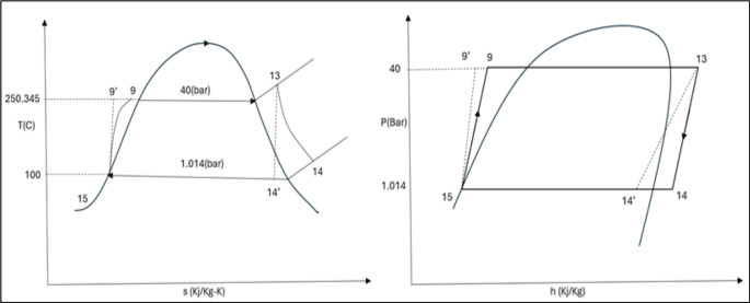
Water is in saturated liquid phase at 100˚C at the condenser exit in the Rankine cycle.
An average value of a product of transmittance and absorbance (ταav.) for the collector glass has been taken as 0.72 for PTC and 0.62 for LFR.
Methodology
Since the availability of solar energy on Earth is in discrete format. Hence, the Simulation of a solar power plant needs solar radiation and uses it in a very precise and accurate manner. Collected monthly mean hourly solar radiation data is applied to the proposed model by Qadeer22 in order to get the intensity of solar radiation on a tilted surface.
 |
1 |
An optimized tilt angle5 for PTC & LFR units has been used for this research to receive maximum solar radiation falling on it.
 |
2 |
Here-
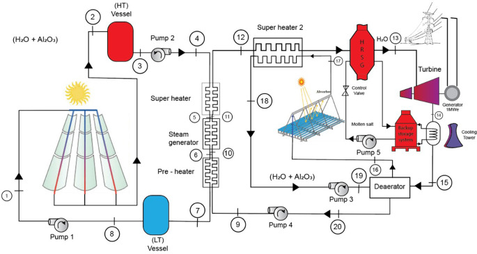
PTC collectors of 650 units array of given specification in Table 1 covering total 2844 m2 land area has been used along with 25 reflectors units of LFR of given specification in Table 2 covering total 3750 m2 land area. For effective heat transfer, there is a twisted tape inserted inside the absorber tubes of both the solar fields. These two solar fields using nanofluid as working fluid and as such coupled, initially PTC cycle transfers heat energy to the working fluid (water) of the Rankine cycle. Thereafter, water enters the superheater 2 and again takes energy from the LFR cycle.
Table 1.
Specification of parabolic trough collector.
| Description | Specification |
|---|---|
| Aperture of parabolic trough | 1.5 m |
| Absorber tube Length | 3.0 m |
| Concentration ratio | 11.23 |
| Glass covers outer diameter | 6.3 cm |
| Glass covers inner diameter | 5.6 cm |
| absorber tube outer diameter | 4.14 cm |
| absorber tube inner diameter | 3.81 cm |
| Absorber tube emissivity | 0.15 |
| Absorber tube coating | Selective |
| Glass cover emissivity | 0.88 |
| Absorber tube type | Tape twisted |
| Tape twist ratio | 4 |
| No. Of units | 650 |
| Connected in | Series |
Table 2.
Specification of Liner Fresnel Reflector.
| Description | Specification |
|---|---|
| Width of reflector | 60.0 cm |
| Length of reflector | 250 m |
| Absorber tube Length | 250 m |
| Distance between reflectors (pitch) | 70.0 cm |
| Glass covers outer diameter | 12.0 cm |
| Glass covers inner diameter | 11.5 cm |
| absorber tube outer diameter | 7.0 cm |
| absorber tube inner diameter | 6.6 cm |
| Absorber tube emissivity | 0.12 |
| Absorber tube coating | Selective |
| Glass cover emissivity | 0.86 |
| Absorber tube type | Tape twisted |
| Tape twist ratio | 4 |
| No. Of units | 25 |
| Hight of receiver | 7.0 m |
During analysis of 650 PTC collectors’ array, a constant K is introduced:
 |
3 |
For N identical collector’s array
 |
4 |
 |
5 |
Finally, useful energy output from the PTC collectors’ array can be given as
 |
6 |
Water starts changing phase as it passes through pre-heater, steam-generator and comes out as superheated steam from super heater 1 as shown in Fig. 1.
Fig. 1.
Block diagram of hybrid solar power plant.
Optical thermal efficiency of the system can be given as:
 |
7 |
Instantaneous thermal efficiency of collector array system can be given as:
 |
8 |
Detailed block diagram of solar power plant is shown in Fig. 1.
Overall efficiency of these devices is assumed as 90%.
 |
9 |
Total energy gain while passing through pre-heater, steam generator and superheater is:
 |
10 |
After coming out from superheater 1, steam enters to heat exchanger of LFR solar cycle for adequate superheating. At this point superheated steam again receives heat energy from ‘superheater 2’ for further superheating takes place with heat transfer efficiency of 90%.
 |
11 |
Total energy gain while passing through super heater again is:
 |
12 |
Superheated steam enters to the steam turbine where it expands from 4 MPa to 0.1014 MPa.
Isentropic efficiency of the steam turbine is assumed as 90%
 |
13 |
Here h14 is the enthalpy after isentropic expansion. After expansion, total power output from the turbine is:
 |
14 |
Different processes of Rankine cycle are shown on T-s & P-h diagram in Fig. 2.
Fig. 2.
P-h & T-s diagram of Rankine cycle.
Thermophysical properties of basic components of nanofluid i.e. water and Al2O3 used in solar cycles of plant are shown in Table 3.
Table 3.
Thermophysical properties of nano particle Al2O3 and water at NTP.
| Properties | Water | Al2O3 |
|---|---|---|
| Density | 997 | 3970 |
| Specific Heat | 4179 | 765 |
| Viscosity | 0.895 | … |
| Thermal conductivity | 0.613 | 40 |
Energy developed from the turbine is transferred to generator which converts the mechanical energy got from steam turbine into electrical energy at 90% efficiency rate. All pumps working in this plant are assumed to be 90% isentropic efficient.
For Rankine cycle
 |
13 |
Similarly, h’9 is the enthalpy after isentropic increment of pressure by the pump. Work absorbed by the pump to run the Rankine cycle is:
 |
14 |
There are many types of hydraulic pumps are running in the plant but, assumed that, only Rankine cycle pump is absorbing the energy from steam turbine in this simulation. Working hours for this simulation work has been selected as 6 h from 10:00 AM to 16:00 PM per day throughout the year.
Deaerator in the system is attached to remove the dissolved gasses from boiler (solar cycles) feed water.
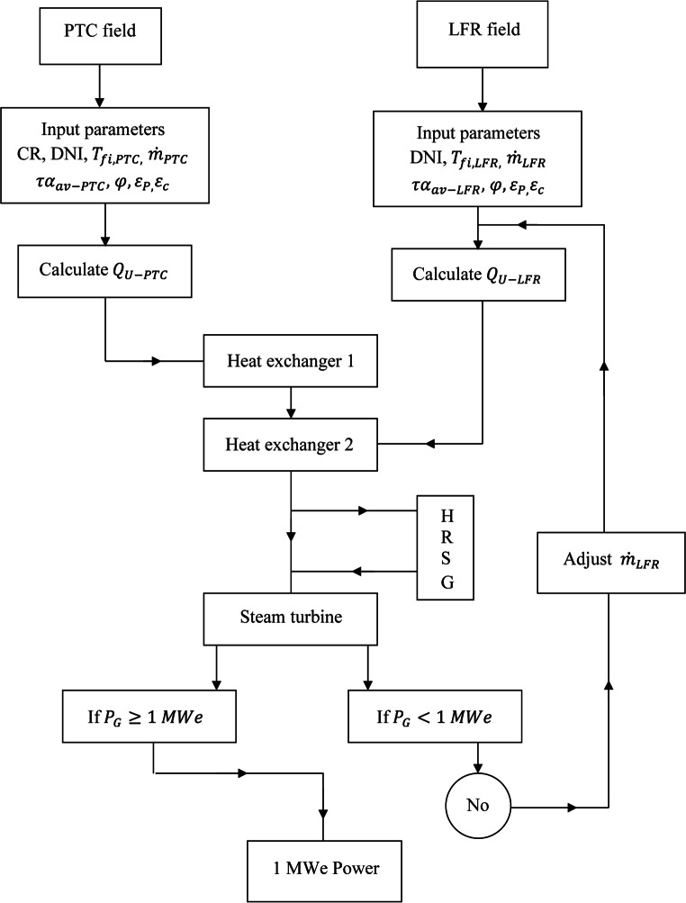
A flow chart for the better understanding of energy flow in the system is given in Fig. 3.
Fig. 3.
Flow chart of the simulation system.
Results and discussions
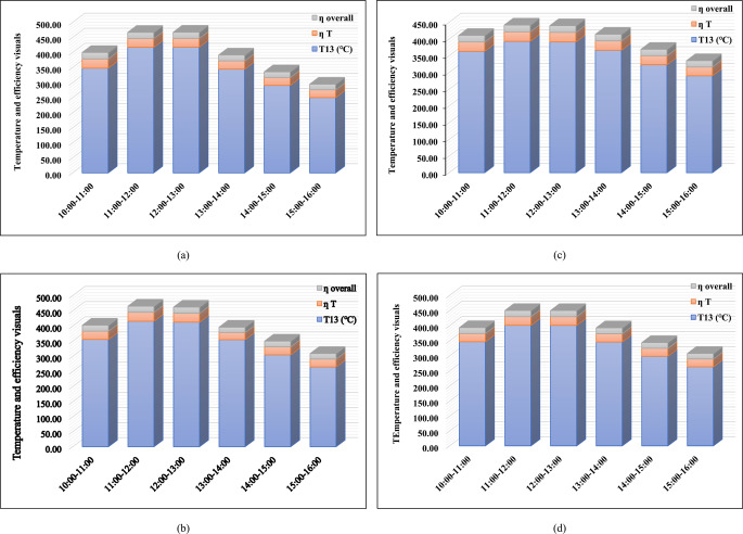
Simulation of hybrid solar power plant using PTC and LFR solar fields simultaneously, where PTC and LFR has been arranged on seasonal optimum tilt angle βTaylor and both the solar cycles are running with Al2O3 + water nanofluid. Developed useful energy by these solar cycles are been transferred to the Rankine cycle consecutively. By the alternate arrangement of both the solar cycle, input temperature of steam for steam turbine is quite high that can produce superheated steam at 40 bar pressure. Steam turbine efficiency (ηT) and overall efficiency of Rankine cycle (ηoverall) is shown in Fig. 4.
Fig. 4.
Seasonal variations (a) Jan-winter (b) March-autumn, (c) June-summer (d) Sept-spring of monthly mean hourly temperature and their respective turbine efficiency and overall efficiency of Rankine cycle.
Highest values of efficiencies are found as 21.25% for ηoverall for Rankine cycle and 30.91% for ηT for steam turbine in the month of January in 10:00–11:00 time slot. Minimum values of efficiencies are found as 15.19% (ηoverall) and 20.33% (ηT) in the month of November in the time slot of 10:00–11:00. Temperature gain from solar cycles to Rankine cycle is increasing from morning to noon then decreasing pattern is shown from noon to evening. But, pattern of efficiency is little bit different. As it follows the decreasing pattern from morning to evening in January. Except January, it follows same pattern as temperature.
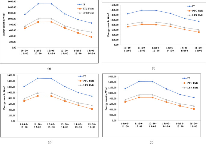
Figure 5 describes the variation of solar radiation falling on tilted surface (IT) and useful energy developed by PTC array and LFR field. As radiation values are increasing from morning to noon, useful energy (Qu) is also increasing and thereafter, it is falling till evening. During peak hours 11:00 to 13:00 these values are quite high that makes CSP quite efficient.
Fig. 5.
Monthly mean hourly solar radiation falling on tilted surface of collectors and useful heat gain by both the solar fields (a) January (b) March (c) June (d) Sept.
Maximum value of DNI from proposed model by Qadeer et al.22 is 1538.24 Wh/m2. The values of maximum useful energy (Qu) developed from PTC & LFR field are 907.47 Wh/m2 & 1016.42 Wh/m2 in the month of December in time slot of 11:00–12:00. Total energy transfer to the Rankine cycle is also maximum in same time slot but, efficiency values are not matching with it. It shows that there must be comparison between energy transfer and operational design of the working system.
Minimum value of the DNI is 821.51 Wh/m2. At this DNI, Qu from PTC is 346.62 Wh/m2, both of these minimum values are in the month of December in the time slot of 15:00–16:00 whereas, the minimum value of Qu from LFR is 516.32 Wh/m2 in the month of August in time slot of 15:00–16:00. It shows that as working hours fall towards evening, energy output decreasing drastically.
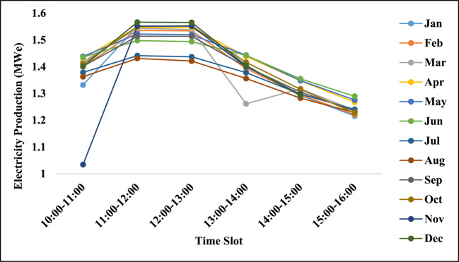
Developed power from steam turbine transferred to the generator where mechanical energy got converted into electrical energy at 90% generator efficiency. Figure 6 shows electrical energy developed from generator in MWe. Minimum value of generated power from generator is 1.03 MWe in November in the time slot of 10:00–11:00. Whereas, maximum value of generated power is 1.57 MWe in the month of December in 11:00–12:00 time slot. Simulated solar power plant system is capable to provide 1 MWe power during selected working hours throughout the year.
Fig. 6.
Production of electricity by generator throughout the year during selected hours.
Energy backup system
Since huge amount of energy is reaching at condenser side after expansion from steam turbine, an energy backup system is attached here to reduce the loss of energy and utilize according to the requirement.
Energy backup system contains a storage tank, pump, control valve and heat recovery steam generator (HRSG). Storage tank contains 60% sodium nitrate & 40% potassium nitrate (by weight) as working fluid, which is commonly called solar salt.
Solar systems are diurnal in nature. Hence, during night hours or cloudy weather condition the flow of energy starts from storage system to the main line. energy storage system is attached along with a control valve. Control valve allows the flow of molten salt according to the requirement and energy transfer takes place in heat recovery steam generator (HRSG) tank.
A cooling tower is attached in the system at condenser side to remove the extra heat from the system.
Maximum and minimum temperature values attain in PTC and LFR solar fields and at the inlet point of Rankine cycle are shown in Table 4.
Table 4.
Details of Maximum, Minimum temperature in solar cycles and Rankine cycle.
| PTC Array | LFR Field | Rankine Cycle | |
|---|---|---|---|
| Maximum Temperature (˚C) |
326.65 In the month of January. Time slot: 11:00 to 12:00 |
425.43 In the month of January. Time slot: 12:00 to 13:00 |
418.13 In the month of January. Time slot: 12:00 to 13:00 |
| Minimum Temperature (˚C) |
241.56 In the month of December Time Slot: 15:00 to 16:00 |
295.73 In the month of December Time slot: 15:00 to 16:00 |
244.79 In the month of December Time slot: 15:00 to 16:00 |
Validation
Presented research work is based on CSP system and utilize the solar power to generate electricity by the help of Rankine cycle. Whole setup is designed to generate 1MWe throughout the year. Found results are showing the setup is capable to do so. Some other researchers did same work for different locations, among them Desai et al.18 simulate the solar power plant of 1 MWe capacity for Gurgaon near New Delhi, India and Yao et al.26 did the same for Beijing, China. For the validation purpose, comparison of this research work has been done with these researchers in Table 5.
Table 5.
Comparison of present work with from other researchers work.
| S. No. | Description | Desai et al.18 | Yao et al.26 | Present study |
|---|---|---|---|---|
| 1 | Solar Field | PTC & LFR | Helio state | PTC & LFR |
| 2 | Location | Gurgaon near New Delhi, India | Badaling, Beijing, China | New Delhi, India |
| 3 | DNI value | 600 W/m2 DNI throughout the year | 830 W/m2 DNI throughout the year | Based on monthly mean hourly radiation in Wh/m2 through the year22 |
| 4 | CSP field system | LFR is integrated with PTC contribute to produce superheated steam for Rankine cycle | Helio state | PTC produces superheated steam thereafter, LFR increases the degrees of superheating of steam for Rankine cycle |
| 5 | Working fluids | Therminol VP1 in both the solar fields and water in Rankine cycle | Oil for Helio state and water in Rankine cycle | Nanofluid (Al2O3 + water) for both the solar cycles and water in Rankine cycle and molten salt in storage system |
| 6 | Type of receiver | Simple tubes for both the solar field’s receivers | Central receiver | Twisted tape tube is used for both the solar field’s receivers |
| 7 | Temperature limits |
PTC field − 390˚C LFR field- 256.1˚C At turbine inlet- 350 ˚C |
Central Receiver- 400˚C At turbine inlet- 390˚C |
Maximum temperature produced is- PTC field- 326.65˚C LFR field- 425.43˚C At turbine inlet- 418.13˚C |
| 8 | Pressure limits (Rankine cycle) | Maximum- 40 bar Minimum- 3.46 bar | Maximum- 23.54 bar Minimum- 0.073 bar | Maximum- 40 bar Minimum- 1.014 bar |
| 9 | Land area required |
PTC field- 8175 m2 LFR field- 7020 m2 |
Helio stat- 10,000 m2 |
PTC field- 2844 m2 LFR field- 3750 m2 |
Most of the comparison points are based on design conditions but 9th point in the above Table is showing the land area required for the simulated systems. It can be seen from the Table that the land area required for 1 MWe is minimum in the present study.
Conclusion
Solar power plant intended to take advantages of CSP system has been simulated successfully to produce 1 MWe throughout the year. different types of working fluids have been used in different parts of the power plant. Nanofluid in both the solar cycles i.e. PTC and LFR cycles, water in Rankine cycle and molten salt for energy storage system. The overall power plant can be concluded as-.
CSP system of the power plant is designed and working successfully with nanofluid (Al2O3 + Water) for optimum harvesting of solar energy.
A consecutive arrangement of PTC and LFR is working successfully to produce superheated steam at 40 MPa pressure.
Maximum temperature in PTC solar cycle is 326.65 ˚C in time slot 11:00–12:00 in the month of January and in LFR solar cycle its value is 425.43 ˚C in time slot 12:00–13:00 in the month of January. Whereas, minimum temperature is 241.56 ˚C in 15:00–16:00 time slot in the month of December in PTC cycle and 295.73 ˚C in LFR cycle in same time slot and month.
Maximum temperature attained in Rankine cycle at inlet of the turbine is 418.13 ˚C in time slot 12:00–13:00 in the month of January. Whereas, minimum temperature at turbine inlet is 244.79 ˚C in 15:00–16:00 time slot in the month of December. Overall efficiency of the Rankine cycle is 21.25%.
Heat energy backup system is attached successfully to retain the energy for night hours or cloudy weather conditions or whenever is needed.
Control valve in energy backup system is to control the flow of molten salt according to requirement.
Nomenclature
- Ac
Total area of the collector (m2)
- Ap
Aperture area of collector (m2)
- FR
Heat removal factor
- Ul
Overall heat loss coefficient (W/m2-K)
- ṁ
Mass flow rate (kg/sec)
- τ
Transmissivity of glass cover
- α
Absorptivity of glass cover
- N
Number of reflector units
- Tfi
Inlet temperature of working fluid (K)
- Ta
Ambient temperature (K)
- Cp
Specific heat capacity at constant pressure (J/kg-K)
- Qu
Useful energy (Wh/m2)
- S
Energy falling on collector surface (Wh/m2)
- ER
Energy gain in Rankine cycle (W)
- EPTC
Energy in PTC solar cycle (W)
- ELFR
Energy in LFR solar cycle (W)
- CR
Concentration ratio
- ϵp
Emissivity of receiver
- ϵc
Emissivity of cover
- φ
Latitude of the location
- ηT isen
Isentropic efficiency of steam turbine
- ηP isen
Isentropic efficiency of a pump
- h
Specific enthalpy at given points (J/kg)
- ηoptical
Optical efficiency of the collector
- ηinst. thermal
Instantaneous thermal efficiency of the collector
Author contributions
A.Q. and M.P. wrote the main manuscript text and prepared Figs. 1, 2 and 3. O.K. and P.K. performed the data analysis. Z.Y. and A.A. conducted the experiments. M.J.I. supervised the project and provided critical revisions to the manuscript. All authors reviewed the manuscript.
Data availability
All data generated or analysed during this study are included in this published article.
Declarations
Competing interests
The authors declare no competing interests.
Footnotes
Publisher’s note
Springer Nature remains neutral with regard to jurisdictional claims in published maps and institutional affiliations.
References
- 1.Yılmaz, I. H. & Mwesigye, A. Modeling, simulation and performance analysis of parabolic trough solar collectors: a comprehensive review. Appl. Energy. 225, 135–174. 10.1016/j.apenergy.2018.05.014 (2018). [Google Scholar]
- 2.Aramesh, M., Pourfayaz, F. & Kasaeian, A. Numerical investigation of the nanofluid effects on the heat extraction process of solar ponds in the transient step. Sol Energy157, 869–879. 10.1016/j.solener.2017.09.011 (2017). [Google Scholar]
- 3.Pourmoghadam, P., Farighi, M., Pourfayaz, F. & Kasaeian, A. Annual transient analysis of energetic, exergetic, and economic performances of solar cascade organic rankine cycles integrated with PCM-based thermal energy storage systems. Case Stud. Therm. Eng.28, 101388. 10.1016/j.csite.2021.101388 (2021). [Google Scholar]
- 4.Ponte, J. G. M. S. & Rocha, P. A. C. Technical and Financial Viability of a 1 MW CSP Power Plant with Organic Rankine Module: Case Study for a Northeastern Brazilian City Preprint submitted to Int. J. Energy Env Eng.18. 10.32388/NKKKOI (2023).
- 5.Qadeer, A., Khan, M. E. & Alam, S. Tilt angle optimisation by Taylor’s series expansion for maximum solar radiation in humid subtropical regions of India. Int. J. Ambient Energy. 43 (1), 6702–6708. 10.1080/01430750.2022.2044380 (2022). [Google Scholar]
- 6.Abu-Zeid, M. A. et al. Performance enhancement of flat-plate andparabolic trough solar collector using nanofluid for water heating application. Results Eng.21, Article101673. 10.1016/j.rineng.2023.101673 (2024). [Google Scholar]
- 7.Alfellag, M. A. et al. Green synthesized clove-treated carbon nanotubes/titanium dioxide hybrid nanofluids for enhancing flat-plate solar collector performance. Appl. Therm. Eng.246(1), Article 122982. 10.1016/j.applthermaleng.2024.122982 (2024). [Google Scholar]
- 8.Struchalin, P. G., Zhao, Y. & Balakin, B. V. Field study of a direct absorption solar collector with eco-friendly nanofluid. Appl. Therm. Eng.243, Article 122652. 10.1016/j.applthermaleng.2024.122652 (2024). [Google Scholar]
- 9.Struchalin, P. et al. Performance of a tubular direct absorption solar collector with a carbon-based nanofluid. Int. J. Heat. Mass. Transf.179, Article 121717. 10.1016/j.ijheatmasstransfer.2021.121717 (2023). [Google Scholar]
- 10.Balakin, B. V., Stava, M. & Kosinska, A. Photothermal convection of a magnetic nanofluid in a direct absorption solar collector. Sol Energy. 239, 33–39. 10.1016/j.renene.2020.10.017 (2022). [Google Scholar]
- 11.Kumar, S., Sharma, V. & Samantaray, M. R. Chander.Experimental investigation of a direct absorption solar collector using ultra stable gold plasmonic nanofluid under real outdoor conditions. Renew. Energy. 162, 1958–1969. 10.1016/j.renene.2020.10.017 (2020). [Google Scholar]
- 12.Karami, M., Akhavan-Bahabadi, M., Delfani, S. & Raisee, M. Experimental investigation of cuo nanofluid-based direct absorption solar collector for residential applications. Renew. Sustain. Energy Rev.52, 793–801. 10.1016/j.rser.2015.07.131 (2015). [Google Scholar]
- 13.Delfani, S., Karami, M. & Akhavan-Behabadi, M. Performance characteristics of a residential-type direct absorption solar collector using mwcnt nanofluid. Renew. Energy. 87, 754–764. 10.1016/j.renene.2015.11.004 (2016). [Google Scholar]
- 14.Alsaady, M. et al. An experimental investigation on the effect of ferrofluids on the efficiency of novel parabolic trough solar collector under laminar flow conditions. Heat. Transf. Eng.40, 9–10. 10.1080/01457632.2018.1442309 (2019). [Google Scholar]
- 15.Struchalin, P. G. et al. Hybrid nanofluid in a direct absorption solar collector: Magnetite vs. carbon nanotubes compete for thermal performance. Energies. 15 (5), Article1604. 10.3390/en15051604 (2022). [Google Scholar]
- 16.Abu-Zeid, M. A. et al. Performance enhancement of flat-plate and parabolic trough solar collector using nanofluid for water heating application. Results Eng.21, 101673. 10.1016/j.rineng.2023.101673 (2024). [Google Scholar]
- 17.Ghodbane, M. et al. 4E (energy, exergy, economic and environmental) investigation of LFR using MXene based silicone oil nanofluids. Sustain. Energy Technol. Assess.49, Article 101715. 10.1016/j.seta.2021.101715 (2022). [Google Scholar]
- 18.Desai, N. B., Bandyopadhyay, S., Nayak, J. K., Banerjee, R. & Kedare, S. B. Simulation of 1 Mwe Solar Thermal Power Plant, 2013 ISES Solar World Congress, 2013 the Authors. Published by Elsevier Ltd.
- 19.Fernandez-Garcia, A., Zarza, E., Valenzuela, L. & Perez, M. Parabolic-trough solar collectors and their applications. Renew. Sustain. Energy Rev.14 (7), 1695–1721. 10.1016/j.rser.2010.03.012 (2010). [Google Scholar]
- 20.Cuce, P. M., Guclu, T. & Cuce, E. Design, modelling, environmental, economic and performance analysis of parabolic trough solar collector (PTC) based cogeneration system assisted by thermoelectric generator. Sustain. Energy Technol. Assess.24, 103745. 10.1016/j.seta.2024.103745 (2024). [Google Scholar]
- 21.ASHRAE Handbook. Climate Design Data. (2009). https://energyplus.net/weather-region/asia_wmo_region_2/IND
- 22.Qadeer, A., Khan, M. E. & Alam, S. Estimation of solar radiation on tilted surface by using regression analysis at different locations in India. Distrib. Generation Altern. Energy J.35 (1), 1–18. 10.13052/dgaej2156-3306.3511 (2020). [Google Scholar]
- 23.Qadeer, A., Alam, S., Jafri, H. Z. & Akram, W. Solar collector tilt angle optimization for maximum solar irradiation in Lucknow, Uttar Pradesh, India, The Author(s), under exclusive license to Springer Nature Singapore Pte Ltd. In Advances in Heat Transfer and Fluid Dynamics, Lecture Notes in Mechanical Engineering (eds M. A. Siddiqui et al.), 417–423 (2024). 10.1007/978-981-99-7213-5_32
- 24.Ladkany, S., Culbreth, W. & Loyd, N. Molten salts and applications I: molten salt history, types, thermodynamic and physical properties, and cost. J. Energy Power Eng.12, 507–516. 10.17265/1934-8975/2018.11.001 (2018). [Google Scholar]
- 25.Motloung, T., Quak, H., Anand, N. & Duin, R. The Zero-Emission City Logistics Maturity model –what do inner city SMEs know about planned zero-emission zones. Transp. Res. Procedia. 79, 194–201. 10.1016/j.trpro.2024.03.027 (2024). [Google Scholar]
- 26.Yao, Z., Wang, Z., Lu, Z. & Wei, X. Modeling and simulation of the pioneer 1 MW solar thermal central receiver system in China. Renew. Energy. 34, 2437–2446. 10.1016/j.renene.2009.02.022 (2009). [Google Scholar]
Associated Data
This section collects any data citations, data availability statements, or supplementary materials included in this article.
Data Availability Statement
All data generated or analysed during this study are included in this published article.


