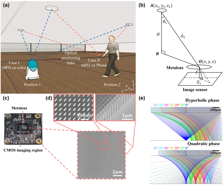
Figure 1:
The positioning device and its working principle. (a) Schematic of the MPD application scenario. The MPD can be integrated into the mobile phone or robot and then determine its own position by imaging the beacon LEDs with known locations on the ceiling. (b) Working principle of the MPD. The position of the device is related with the imaging positions of beacon LEDs on the CMOS sensor. f: metalens focal length, X 1: distance between the image of the i-th LED and the center point of CMOS sensor, d 1: distance between the i-th LED and the center point of metalens. (c) The photograph of the MPD, in which the CMOS imaging region and the metalens region are marked. (d) The SEM images of the fabricated metalens structures. (e) The simulated focusing light rays of hyperbolic phase metalens and quadratic phase metalens. The different colors from left to right represent the light rays with incident angles of 0°, 10°, 20°, 30°, 40°, 50°, and 60°, respectively.

