Abstract
Vascular graft thrombosis is a long-standing clinical problem. A myriad of efforts have been devoted to reducing thrombus formation following bypass surgery. Researchers have primarily taken a chemical approach to engineer and modify surfaces, seeking to make them more suitable for blood contacting applications. Using mechanical forces and surface topology to prevent thrombus formation has recently gained more attention. In this study, we have designed a bilayered porous vascular graft capable of repelling platelets and destabilizing absorbed protein layers from the luminal surface. During systole, fluid penetrates through the graft wall and is subsequently ejected from the wall into the luminal space (Luminal Reversal Flow - LRF), pushing platelets away from the surface during diastole. In-vitro hemocompatibility tests were conducted to compare platelet deposition in high LRF grafts with low LRF grafts. Graft material properties were determined and utilized in a porohyperelastic (PHE) finite element model to computationally predict the LRF generation in each graft type. Hemocompatibility testing showed significantly lower platelet deposition values in high versus low LRF generating grafts (median±IQR = 5,708 ± 987 and 23,039 ± 3,310 platelets per mm2, respectively, p=0.032). SEM imaging of the luminal surface of both graft types confirmed the quantitative blood test results. The computational simulations of high and low LRF generating grafts resulted in LRF values of −10.06 μm∕s and −2.87 μm∕s, respectively. These analyses show that a 250% increase in LRF is associated with a 75.2% decrease in platelet deposition. PHE vascular grafts with high LRF have the potential to improve anti-thrombogenicity and reduce thrombus-related post-procedure complications. Additional research is required to overcome the limitations of current graft fabrication technologies that further enhance LRF generation.
Keywords: Vascular graft, Porohyperelastic, Luminal reversal flow, Polymer biomaterial, Hemocompatibility
1. Introduction
According to the American Heart Association, cardiovascular diseases (CVD) claimed close to 1 million lives in 2020 in the United States where the mortality rate of heart disease and stroke is higher than all forms of cancer and Chronic Lower Respiratory Disease combined annually (Virani et al., 2021). Atherosclerosis is a fatal form of CVD and is a significant contributor to CVD-related mortality. In atherosclerotic patients, fibrous fatty lesions are formed in the arterial wall (Libby et al., 2019). These lesions reduce blood flow leading to an inadequate supply of nutrients and oxygen to downstream tissues. Depending on the location and severity of the disease, atherosclerosis can cause stroke, myocardial infarction, and limb amputation. The main treatment modalities for atherosclerotic lesions include vascular bypass surgery, balloon angioplasty, and stent deployment. In bypass surgery, blood flow is redirected from upstream to downstream tissues bypassing the blocked region. Autologous blood vessels such as the saphenous vein, internal mammary artery, and radial artery are gold standards in bypass procedures (Pashneh-Tala et al., 2016), however, the availability of these tissues is limited due to pre-existing vascular disease or prior harvesting of these tissues (Desai et al., 2011; Aavik et al., 2019). Alternatively, synthetic polymer-based vascular grafts such as expanded polytetrafluoroethylene (ePTFE) and Dacron have been widely and successfully utilized in bypass procedures of large arteries (Bosiers et al., 2006; Pulli et al., 2010; Rychlik et al., 2014; Roll et al., 2008). On the other hand, the use of prosthetic small-diameter vascular grafts (inner diameter < 6 mm) in bypass surgeries results in post-implantation complications including thrombosis (Ravi and Chaikof, 2010; Seifu et al., 2013). Non-physiologic shear stress due to compliance mismatch, non-optimized anastomotic geometry, and the presence of a foreign biomaterial are the primary drivers of platelet activation (Jamiolkowski et al., 2016; Ruggeri, 2009; Lippi et al., 2011; Casa et al., 2015). Activated platelets and polymerized fibrin lead to thrombus formation and subsequent acute arterial occlusion.
Prevention of thrombosis following surgical procedures has been the center of attention for many researchers over the past several decades. Most of these efforts, however, have concentrated on inventing and designing chemical solutions to disrupt the coagulation cascade, improve hydrophilicity, and promote endothelialization. In particular, chemical compounds such as heparin, polyethylene glycol (PEG), vascular endothelial growth factor (VEGF), RGD peptides, and monoclonal antibodies have been conjugated to blood-contacting surfaces to improve hemocompatibility (Gray et al., 2012; Qiu et al., 2017; Kuang et al., 2018; Deglau et al., 2012; Tatterton et al., 2012; Hu et al., 2017; Antonova et al., 2016; Torem et al., 1988). Chemical approaches have several drawbacks including the technical difficulties of surface conjugations, loss of chemical activity over time, and potential initiation of thrombocytopenia with heparin Qiu et al. (2017) and Ahmed et al. (2007). As an alternative, mechanical and geometrical design (e.g., surface topology engineering) may be an attractive method for keeping a blood-contacting surface clean from thrombosis. For instance, low-roughness surfaces have been shown to significantly reduce platelet adhesion to the surface (Dong et al., 2018). Other researchers have also developed surfaces with active wrinkles (wrinkled during diastole and unwrinkled during systole) and demonstrated a significant reduction in platelet adhesion (Pocivavsek et al., 2019).
We have previously developed a porohyperelastic (PHE) finite element (FE) framework to model the interstitial fluid flow through a vascular graft’s porous and layered wall structure (Behrangzade et al., 2022). This FE framework models the fluid flow penetration through the graft wall during systole which can be reversed and ejected out of the wall into the luminal space during diastole (Luminal Reversal μFlow or LRF). To maximize LRF, our optimization results showed that a thick, highly permeable, and compressible inner layer adjacent to a thin, highly impermeable, and incompressible outer layer in a highly deformable (low tensile stiffness) vascular graft are required. Following the creation of this FE framework, we studied the thermal treatment of electrospun Polycaprolactone (PCL) conduits to create an impermeable graft (Behrangzade et al., 2023). This method is called thermobonding as it thermally bonds the electrospun PCL fibers and can be used in the fabrication of an impermeable outer layer.
We hypothesize that a vascular graft with higher LRF will have lower platelet deposition per surface area compared to a lower LRF graft. The goal of this work is therefore to design and fabricate bilayered PHE vascular grafts and test this hypothesis by performing in-vitro hemocompatibility tests and comparing high versus low LRF graft types. PHE FE models are also used herein to confirm our graft types have significantly different LRF values.
2. Methods
In this work, two bilayered graft types were designed (Section 2.1) to test our hypothesis. This involved mechanical characterization of the materials within the bilayered grafts (Section 2.2), creation of a PHE FE model to determine their material properties (Section 2.3), prediction of the LRF generated in bilayered graft designs (Section 2.4), and finally testing of the blood compatibility in a mock flow loop (Section 2.5).
2.1. Bilayered graft design and fabrication
Prior studies by our research group (Behrangzade et al., 2022, 2023) have shown that the thickness, permeability, and material properties of layers in a bilayered graft determine the generated LRF. As stated before, we require a thick highly permeable and compressible inner layer and a thin highly impermeable, and incompressible outer layer in a highly deformable vascular graft (low tensile stiffness) to boost the LRF and increase the probability of platelet repulsion. The primary method of graft fabrication in this work was electrospinning using an IME electrospinner (IME Technologies, Netherlands). Initially, we fabricated single-layered constructs made of the material chosen for each layer. These constructs were mechanically characterized to determine their material properties. We followed the same manufacturing procedures for the fabrication of bilayered grafts used in hemocompatibility tests. Prior to bilayered graft fabrication, we established correlations between the electrospinning volume and the thickness of the layers. Fig. 1 illustrates the layers of the PHE graft in the bilayered design.
Fig. 1.
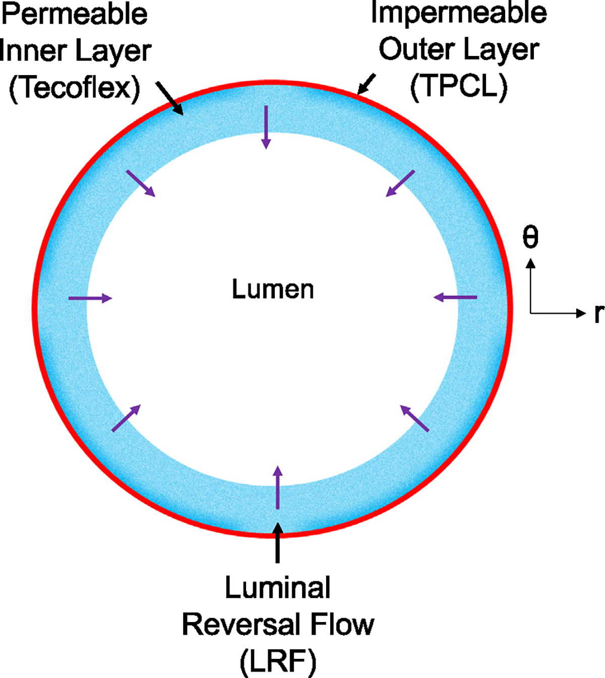
Cross-section of the bilayered PHE graft to demonstrate Luminal Reversal Flow (LRF) using velocity vectors.
Inner layer:
In order to find the most deformable (and available) material for the inner layer, we tested many different polymers uniaxially (data not shown). These polymers (each n = 5) include polycaprolactone (PCL), polyethylene terephthalate (PET), polylactic acid (PLA), poly (lactic-co-glycolic acid) (PLGA), polystyrene (PS), polyurethane (PU from Sigma Aldrich, USA), Tecoflex SG-85 A (PU from Lubrizol, USA), gelatin (from porcine skin) crosslinked at two concentrations of 0.5% and 2.5% genipin in 200 proof ethanol for 24 h in 37 °C. The data indicated that Tecoflex SG-85 A is the most deformable among the tested polymers. Tecoflex is an aliphatic polyether-based thermoplastic polyurethane (PU). In order to create a highly permeable layer, we used an electrospinning method. Tecoflex SG-85 A pellets were dissolved in 1,1,1,3,3,3-Hexafluoro-2-propanol (HFP) solvent to create an 8% w/v solution. The solution was stirred overnight and then loaded into a 5 mL syringe connected to an 18 gauge needle. A 15 kV voltage was applied to the dispenser (a capillary size of 0.6 mm) and the solution was dispensed using a syringe pump at a flow rate of 0.05 mL/min. We spun 8-cm constructs on a collecting Teflon-coated stainless steel mandrel with an outer diameter of 1.1 mm. The working distance between the dispenser and the collecting mandrel was 12 cm. The rotation speed of the mandrel was 300 rpm and the axial translational speed of the dispenser was 300 mm/s. The electrospinning process was done in a controlled environment with a constant humidity of 30% and a temperature of 25 °C. The thickness of the grafts/layers was controlled by the electrospinning volume.
Outer layer:
Creating a highly impermeable outer layer on an electrospun inner layer is challenging using traditional biomanufacturing methods such as porogen leaching and thermally induced phase separation (TIPS). Therefore, we used sequential electrospinning and thermobonding methods to create an impermeable outer layer. We initially electrospun single-layer constructs out of PCL using pellets (Mn = 80,000, Sigma Aldrich) dissolved in HFP solvent to create a 10% w/v solution, again mixing this overnight. The rest of the electrospinning process was identical to Tecoflex. PCL has a low melting temperature of 60 °C which makes it suitable for thermal treatment. We thermally fused the electrospun PCL fibers (thermobonding) in a convective oven to create a highly impermeable construct. These single-layered constructs for mechanical testing were thermobonded at 60 °C for 45 s. The downside of this method is the stiffening effect of the thermobonding process that limits the graft deformability. This occurs due to electrospun fiber fusion, elimination of voids, and the creation of a solid structure. Similar to the inner layer, the thickness was controlled via the electrospinning volume.
Bilayered grafts:
To fabricate the bilayered grafts, we followed the same electrospinning conditions that were used for the fabrication of the single-layered constructs. However, we altered the thermobonding conditions for the bilayered grafts due to the presence of a Tecoflex inner layer. These grafts were thermobonded at 60 °C for 3 min to create a fully impermeable layer. Tecoflex fibers remained unaffected as the melting temperature of this polymer was much higher than PCL. Two graft types were designed and fabricated: graft type 1 (High LRF) and graft type 2 (Low LRF). Both graft types had an inner layer of Tecoflex where the same amount of Tecoflex solution was electrospun in order to have a similar blood-contacting surface area. The outer layers in both graft types were made of thermobonded PCL, however, the low LRF grafts had significantly larger outer layer thickness.
2.2. Mechanical charaterization
To determine the material properties of each layer for computational predictions of LRF, the single-layered constructs were mechanically tested in the circumferential direction while fixed in the axial direction. Tecoflex and PCL (n = 3 each) materials were individually electrospun to create single-layered constructs. The electrospun tubular PCL constructs were subsequently thermobonded. All constructs were cut into 1–1.5 cm segments and cannulated using metallic capillary tubes, sutured, and glued at both ends. The samples were mounted in a custom-made microbiaxial tensile testing device (CellScale Biomaterials Testing, Canada) shown in Fig. 2. The testing chamber of the device was filled with water and controlled for temperature (37 °C). The inlet of the graft was connected to a hydraulic piston filled with water while the outlet was blocked. A pressure transducer was utilized between the piston and the graft inlet and a load cell was used to measure the axial load at the beginning and during the test. The samples underwent 10 loading-unloading cycles between 0 and 120 mmHg of intraluminal pressure (Tamimi et al., 2019). The last cycle was used to determine the circumferential stress–stretch response. The Cauchy stress in the circumferential direction was calculated under the thick-walled () assumption using Eq. (1)
| (1) |
where is the Cauchy stress, is the pressure, is the radius and indices “” and “” represents outer and inner, respectively. Following the mechanical tests, the constructs were cross-sectionally cut to measure thickness using a microscope.
Fig. 2.
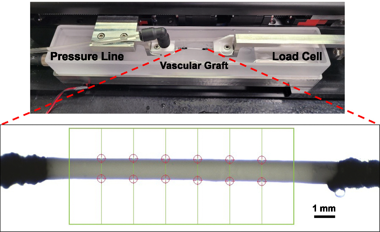
Tubular biaxial tensile testing device used to mechanically characterize the single-layered constructs in the circumferential direction. The chamber was heated to 37 °C. The construct inlet was connected to the pressure line and the outlet was blocked. A camera was used to monitor the construct diameter (red circle tracking in figure). An average of these diameters on the last cycle were used in our analysis.
2.3. Computational Design of Experiment (DOE) and material properties identification
We utilized our PHE FE model (ABAQUS) to determine the Neo-Hookean material properties ( and ) of tubular electrospun Tecoflex and thermobonded PCL based on the mechanical testing data. In this PHE FE model, the porous vascular graft wall consists of a solid matrix with voids filled with fluid. The fluid component follows Darcy’s law (Vande Geest et al., 2011; Smith, 2009; Keyes et al., 2013)
| (2) |
where is the apparent relative fluid velocity (this is also LRF), is the apparent permeability, is the gradient of the pore fluid pressure across the wall, and is the specific weight of the permeating fluid (water). A compressible Neo-Hookean material model was utilized in the PHE simulations. The effective strain energy function of the material is given as Rivlin and Saunders (1951)
| (3) |
where and are material parameters, and is the first deviatoric strain invariant. In the large deformation of a porous vascular graft wall in response to an intraluminal pressure, the voids will also deform thus affecting permeabilities during the deformation. Therefore, we incorporated the effect of the deformation-dependent void ratio on the permeability to create a model with void-dependent permeability. To this end, the modified Gebart equation was utilized to describe the relationship between porosity (or void ratio via is the porosity and is the void ratio) and permeability. This relationship is valid for a medium with randomly distributed fibers in the porosity range of [0.08–0.99].
| (4) |
In this equation is the apparent permeability, is the specific weight of water, is the fiber radius, is the porosity, and is the dynamic viscosity of water. In order to determine the porosity and mean fiber diameter of each material, we used SEM imaging. Figs. 3(a), 3(b) show the porous structure of electrospun Tecoflex and thermobonded PCL. The porosity and mean fiber diameters were calculated using a custom MATLAB script and a previously developed MATLAB-based image processing code (Rabbani and Salehi, 2017; Ezeakacha et al., 2018), respectively. The surface porosity of thermobonded PCL was less than 0.08; therefore, the porosity of thermobonded PCL was assumed to be . Since thermobonded PCL did not have well-defined fibers (due to the fiber fusion during thermobonding), we considered a mean fiber diameter of 1 nm to match the permeability value from the modified Gebart relationship to the experimentally measured permeability value of this graft (). The surface porosity and mean fiber diameter of Tecoflex were approximately and 1.5 μm, respectively. To constitute the DOE domain, elastic modulus () and Poisson’s ratio () were used which were subsequently converted to neo-Hookean material properties for the simulations using Eq. (5) (Slaughter, 2002):
| (5) |
Fig. 3.
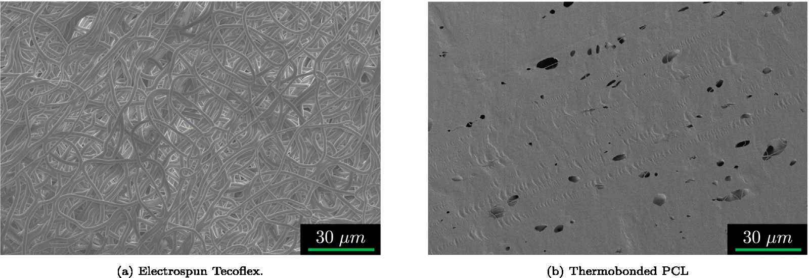
Representative SEM images of the electrospun (a) Tecoflex and (b) Thermobonded PCL. Thermobonded PCL image was adapted from Behrangzade et al. (2023). These images were processed in MATLAB to determine the porosity for the void-dependent permeability calculations in the PHE simulations.
Table 1 indicates the parameter range used in the computational DOE for each individual material. The stress–stretch responses for each material were averaged and used as the reference experimental mechanical response. The physical parameters within the PHE model including the pressurization range (0–120 mmHg), the duration of one cycle, and the rate of pressurization were all matched to the experimental values. The geometrical parameters used in the PHE model were the averaged values of thicknesses and diameters of the constructs for each material.
Table 1.
DOE bounds of elastic modulus and Poisson’s ratio for different materials. These bounds were intentionally chosen to cover a wide range of mechanical responses.
| Bounds of material parameters used in DOE |
||
|---|---|---|
| Tecoflex | TPCL | |
|
| ||
| E (MPa) | 0.35–1.3 | 10–45 |
| 0.1–0.49 | 0.1–0.49 | |
The circumferential Cauchy stress and stretch values were directly extracted from the ABAQUS output files. For each simulation, the computational mechanical response of the graft was compared to the experimental response, and the corresponding data was recorded. In order to find the minimum of the DOE domain, a weighted sum objective function was defined to obtain the best-matched computational mechanical response to the experimental data (Augusto et al., 2012; Marler and Arora, 2004)
| (6) |
where is the elastic modulus, is the maximum stretch ratio in the circumferential direction, and values () are weights used to control the contribution of modulus and stretch to a given fitting procedure. The values of omega used were those that best fit the computational data to a measured experimental response. Following the determination of the combination of the elastic modulus and Poisson’s ratio where the objective function value is minimized, the and values for each material were calculated using Eq. (5). These Neo-Hookean properties were used to computationally predict the LRF generated by each graft type.
2.4. Computational predictions of LRF and compliance for bilayered grafts
Following the determination of Tecoflex and thermobonded PCL material properties and SEM imaging of the bilayered grafts, we used our PHE FE framework to computationally predict the LRF generation and calculate the compliance of the Bilayered grafts. The LRF and compliance calculations were done for the pressure range used in blood tests (20–220 mmHg). LRF was calculated using porosity () and relative fluid velocity () based on the following equation,
| (7) |
where is the apparent relative fluid velocity (LRF), is fluid velocity and is solid matrix velocity. Compliance was calculated using the following equation,
| (8) |
where is the diameter and is the compliance.
2.5. In-vitro platelet deposition testing under pulsatile flow
Bilayered grafts were fabricated using the electrospinning and thermobonding methods described above. SEM imaging was performed using an FEI Apreo microscope to confirm the structure of the grafts with a permeable inner layer and an impermeable outer layer. High LRF and low LRF grafts (each n = 5) were cannulated, sutured, and glued at both ends. We soaked the grafts in 200-proof ethanol for 10 min. The grafts were then washed with sterile PBS three times and stored in a conical tube until the time of the experiment. We prepared 1% Bovine Serum Albumin (BSA), obtained from Fisher Scientific, in PBS solution and circulated it through the circuit (Fig. 4) to coat the blood-contacting surfaces for 10 min under low flow conditions (2 mL/min). The purpose of this coating is to minimize the binding of activated platelets and other blood components to the tubing and connectors. Following BSA coating, the circuit was injected with sterile PBS for a thorough wash. The pressure sensors were calibrated prior to the experiment. We acquired fresh citrated ovine whole blood from the McGowan Institute for Regenerative Medicine (MIRM) animal facility under an approved institutional animal care and use committee (IACUC) protocol. The grafts were exposed to ovine blood flow for 90 min under a pulsatile condition and physiological shear rate, using a mean diameter and flow rate equivalent to rat abdominal aorta (1.1 mm, 10 mL/min, D’Almeida et al. (1995)).
Fig. 4.
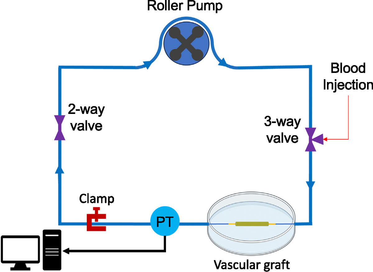
In-vitro mock flow loop used to perform hemocompatibility tests. Fresh citrated whole ovine blood was circulated in a mock flow loop for 90 min under pulsatile flow. A pressure transducer (PT) was used to monitor the pressure range.
The pumps were stopped and grafts were removed after 90 min of circulation. The anastomotic sites (1–2 mm on each side) were excluded from the analysis. These regions were particularly excluded as they were bounded in radial deformation due to proximity to the suture line. Therefore, they did not have sufficient LRF to test our hypothesis. All samples were placed inside conical tubes containing sterile PBS for 10 min to wash off red blood cells. Segments were cut in half with one segment stored in 2% Triton X for the Lactate dehydrogenase (LDH) assay and the other segment stored in a 2.5% glutaraldehyde solution for SEM imaging. For the LDH assay, the segment in 2% Triton X was stirred and mixed for 20 min to lyse the adhered platelets. The segment in the solution was then centrifuged at 250×g for 10 min. The supernatant was added to the wells of a 96-well plate and then the LDH reagents were added to the wells. In order to correlate the number of platelets to the solution absorbance, a calibration curve was generated. To prepare the curve, fresh citrated ovine whole blood was centrifuged at 250×g for 20 min to obtain platelet-rich plasma. The supernatant was added to 2% Triton X solution and subsequently stirred, mixed, and centrifuged at 250×g for 10 min. This solution was then added to the wells at different concentrations followed by the addition of the LDH reagent to the wells. The 96-well plate was incubated at 37 °C for 30 min (Hong et al., 2009; Arazawa et al., 2012; Ye et al., 2010). The absorbances were measured using a plate reader (SpectraMax M2, Molecular Devices LLC, CA) at 490 nm and 650 nm (reference) and subtracted. A second-order polynomial curve was fit to the calibration data points and the correlation was used to calculate the number of platelets. For SEM imaging, samples were maintained in glutaraldehyde solution for 2 h at 4 °C. They were then sequentially dehydrated in incremental percentages of ethanol in DI water, 30%, 50%, 70%, 90% (10 min each) followed by 3 consecutive washes with 100% ethanol (200 proof) (Ye et al., 2010; Khorasani, 2004; Haycox and Ratner, 1993). Samples were then dried overnight under a vacuum and sputter-coated prior to SEM imaging.
2.6. Statistical analysis
The normality of data was assessed using a Shapiro–Wilk test. A Student’s t-test was used to analyze normal data while a Wilcoxon rank sum test (Mann–Whitney) was used to compare data sets that were not normal and could not be transformed to be so. A statistical significance level of 0.05 was used in all analyses ().
3. Results
3.1. Mechanical characterizations and material properties identification
Fig. 5 demonstrates the mechanical response of Tecoflex and thermobonded PCL constructs in the circumferential direction and their corresponding tangential moduli. The maximum stretch ratio of Tecoflex and thermobonded PCL were approximately 1.12 and 1.008, respectively. Tecoflex tangential modulus was significantly lower than thermobonded PCL (p = 0.039).
Fig. 5.
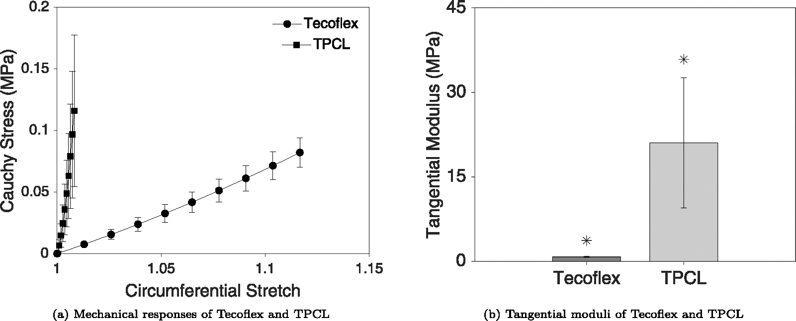
(a) Mechanical responses of Tecoflex SG-85 A and thermobonded PCL (each n = 3) in the circumferential direction. (b) Tangential moduli of both materials at the maximum stretch ratio. The deformation of TPCL constructs was significantly lower than Tecoflex constructs in response to the same pressurization range (p = 0.039). No axial displacement was imposed during these tests, however, the axial loads measured during inflation were all below 0.02N.
Figs. 6(a) and 6(b) represent the objective function values of Tecoflex and thermobonded PCL material, respectively. Green points on these figures indicate the minimum of each domain. Using the DOE minima of both materials, the and values were calculated using Eqs. (5). Table 2 contains the averaged Neo-Hookean properties of these materials.
Fig. 6.
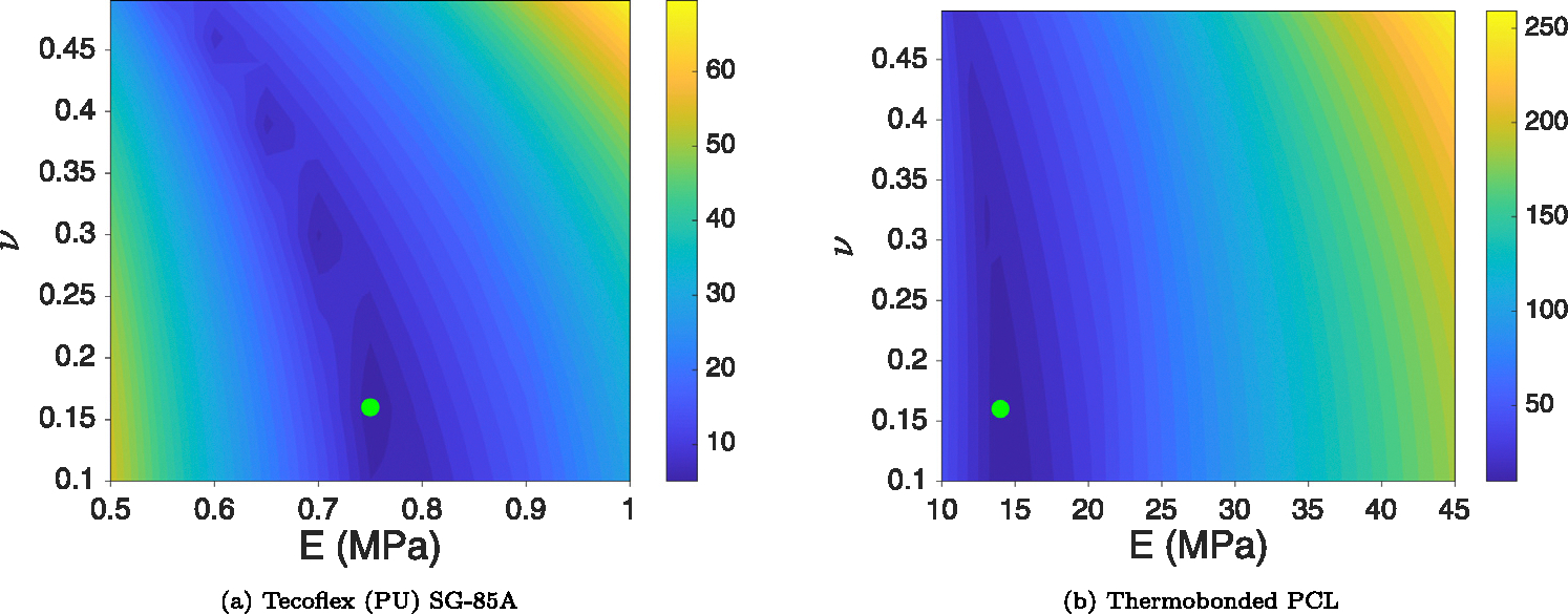
Objective function values in the computational DOE domain for Tecoflex SG-85 A (a) and thermobonded PCL (b). Green points indicate the minimum of the domain based on the objective function values (Eq. (6)). These data points represent each material’s properties and were used to calculate the LRF in each graft type.
Table 2.
Neo-Hookean material properties for low LRF and high LRF grafts.
| Material | (MPa) | (MPa−1) |
|---|---|---|
|
| ||
| Tecoflex | 0.16 | 5.44e−12 |
| Thermobonded PCL | 3.02 | 2.91e−13 |
Figs. 7(a) and 7(b) display the SEM images of the wall structure for both graft types. High LRF grafts had a permeable inner layer and a relatively thin impermeable outer layer whereas the low LRF grafts were composed of a permeable inner layer of similar thickness (to high LRF grafts) and a thick impermeable outer layer.
Fig. 7.
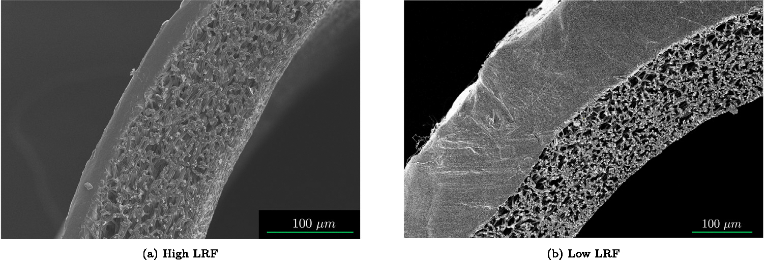
Representative SEM images of high LRF (a) and low LRF (b) showing the permeability and thickness of the graft layers.
3.2. In-vitro platelet deposition tests and computational predictions of LRF and compliance
Fig. 8(a) shows the number of deposited platelets per luminal surface area from the LDH assay following 90 min of blood circulation. The high LRF grafts had significantly lower platelet deposition compared to low LRF grafts. Fig. 8(b) shows the computational LRF predictions using the PHE FE model for each graft type. The high LRF and low LRF grafts generated −10.06 μm∕s and −2.87 μm∕s, respectively. Table 3 shows the characteristics of the bilayered graft types.
Fig. 8.
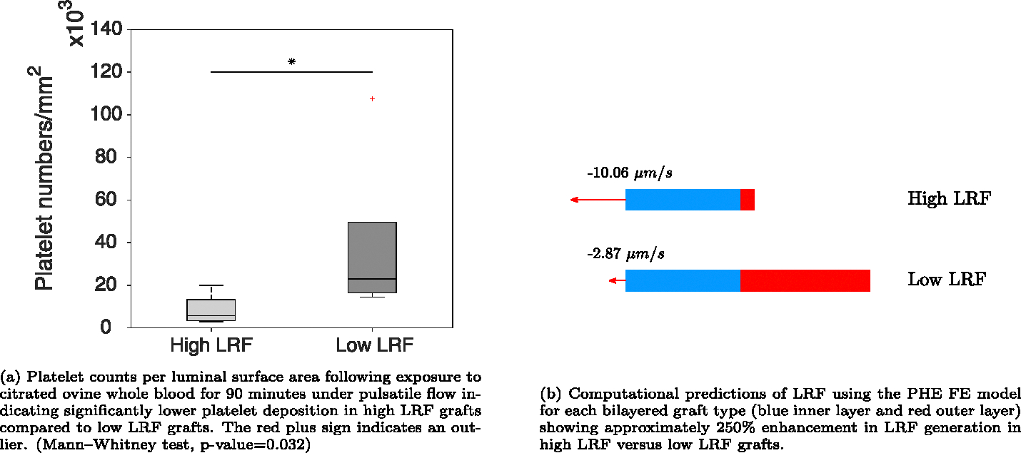
LDH assay results for platelet deposition per luminal surface area and computational predictions of LRF in each graft type using the PHE FE model.
Table 3.
Summary of the bilayered graft types used in in-vitro blood tests (high LRF and low LRF). TPCL is thermobonded PCL.
| Graft type | Layer material |
Layer thickness (μm) |
LRF (μm/s) | Compliance (mmHg−1) | ||
|---|---|---|---|---|---|---|
| L1 | L2 | L1 | L2 | |||
|
| ||||||
| High LRF | Tecoflex | TPCL | 105 | 25 | −10.06 | 1.39e−4 |
| Low LRF | Tecoflex | TPCL | 129 | 157 | −2.87 | 252e−5 |
Fig. 9 displays SEM images from the luminal surface of both graft types exposed to citrated ovine whole blood for 90 min under pulsatile flow. Figs. 9(a) and 9(b) show the luminal surface of high LRF grafts with a very limited number of platelets. Figs. 9(c) and 9(d) show the luminal surface of low LRF grafts indicating platelet aggregations spanning tens of microns.
Fig. 9.
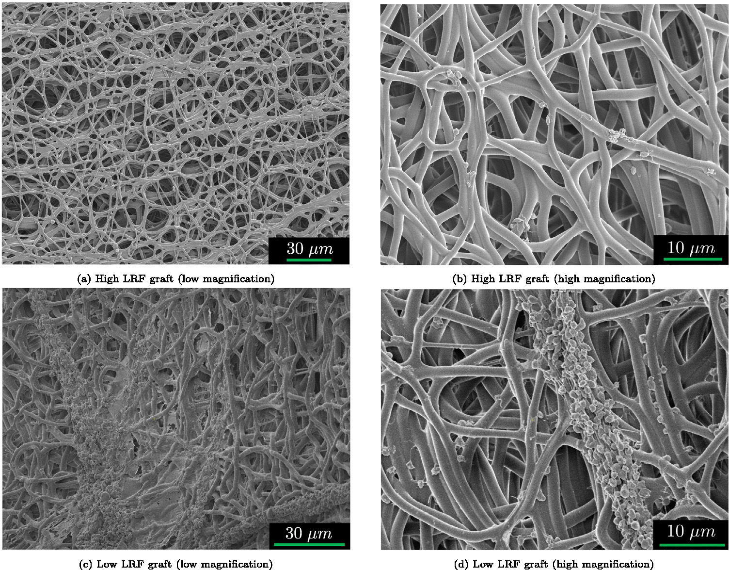
Representative SEM images of high LRF (a–b) and low LRF (c–d) luminal surfaces exposed to citrated ovine whole blood for 90 min under pulsatile flow. Higher LRF grafts had lower platelet deposition compared to the grafts with lower LRF. The SEM images confirm LDH assay results.
4. Discussion
Two vascular graft types (high LRF and low LRF) were designed, fabricated, and tested for the effect of LRF on platelet deposition to the luminal surface using in-vitro blood tests. Grafts were exposed to citrated ovine whole blood under pulsatile flow showing a significant reduction in luminal platelet deposition in high LRF compared to low LRF grafts. The results were confirmed by SEM imaging that showed a visibly higher number of platelets on low LRF compared to high LRF. A PHE FE model was created to computationally predict the generated LRF by each graft type. Computational predictions of LRF were also consistent with LDH and SEM results. Taken together, grafts with higher LRF had lower platelet deposition compared to grafts with lower LRF.
Several researchers have attempted to reduce the formation of thrombosis on synthetic surfaces. The majority of these efforts have concentrated on chemical approaches such as heparin-binding (Begovac et al., 2003; Davidson et al., 2009; Hoshi et al., 2013; Qiu et al., 2017; Yu et al., 2021; Patel, 2021) and zwitterionic coatings (Kim et al., 2020; Ye et al., 2010, 2015). As mentioned earlier, active surface wrinkles have also been developed to mechanically repel platelets from the luminal surface thus reducing thrombosis formation (Pocivavsek et al., 2019). They speculated that the reduction in thrombogenicity is a result of the difficulty of adhesion to curved (wrinkled) surfaces and/or near-surface flow kinetics (disturbances). Soldani et al. performed in-vitro blood experiments on vascular grafts and showed that high-porosity inner layers are less thrombogenic than low-porosity inner layers (Losi et al., 2004). Their research group has also shown a reduction in invivo thrombosis formation of bilayered grafts with a highly porous inner layer and a low porosity outer layer (Soldani et al., 2009). They attributed the lower thrombogenicity of these grafts to less available surface area for platelet adhesion. Their results may have been confounded by the LRF of each graft type in their study. An additional study where the surface area of their biomaterials (inner layer) and LRF are independently controlled would need to be done to delineate the contribution of these two factors.
In our experiment, we controlled for surface between groups and showed a lower platelet deposition in grafts with higher LRF which also had higher matrix deformability. Both of these factors could have contributed to disrupting the formation of adsorbed protein layers and repelling the platelets from the luminal surface. In fact, high LRF could have induced near-surface flow disturbances and higher deformability (matrix radial motion) could have destabilized the deposition of the platelets. We speculate that flow kinetics is a more likely explanation of the observed results as LRF () is calculated based on the relative velocity of the fluid () to the solid matrix () using Eq. (7). Therefore, LRF is at the forefront of encounters with platelets during the interstitial fluid ejection into the luminal space in diastole. However, further investigation is required to decouple the effects of LRF and matrix radial deformation (graft compliance) on platelet deposition.
Prior work has shown that the maximum achievable LRF in a computational model of rat aortic compliance matched graft is −59 μm∕s when exposed to a 80–120 mmHg pulse (Behrangzade et al., 2022). Results here showed that a particular graft design (high LRF) exposed to a 200 mmHg pressure pulse generates an LRF of −10.06 μm∕s. This was sufficient to generate enough momentum to repel platelets that are 2–3 μm (Noris et al., 2014, 2013) in size. Improvements in the biomanufacturing process (e.g., a lower tensile stiffness outer layer) may allow the design of a graft capable of much higher LRF values under physiological pressure ranges.
This study had several limitations. Using the electrospinning technique leads to variations in the thickness of the grafts both in the axial and circumferential direction. This could have a significant effect on the generated LRF and deformability of the vascular grafts in different regions. In addition, the variability in the thickness of the electrospun outer layer was a limiting factor for the thermobonding of a PCL outer layer. The thermobonding of an outer layer with a thickness below a threshold did not result in the creation of an impermeable layer due to the insufficient number of fibers in different regions. Another potential limitation in this work may have been unintentional small alterations in inner layer density resulting from thinning of the outer layer during thermobonding. In other words, the low LRF graft type had a thicker outer layer by design which may have generated a larger contraction force on the inner layer during thermobonding. This larger force might have imposed an inward radial displacement to the inner layer causing a denser structure (lower porosity). To minimize this potential issue, all efforts were made to ensure the inner layer density was not different between high versus low LRF graft types during manufacturing. For example, both grafts had inner layers composed of the same material, were electrospun using identical settings (flow rate, voltage, etc.), and were thermobonded using the same time and temperature conditions. However, future studies should be used to identify if these changes lead to alterations in LRF.
Although grafts were washed with PBS following the blood tests, a red color was sometimes visible in the grafts due to their thick porous inner layer. This red color is particularly coming from the time window between priming the circuit with blood and starting the pumps. During this time, all blood components including red blood cells (RBCs) can penetrate through the porous structure of the inner layer as the diameter of an ovine RBC is approximately 4 to 5 μm (Adili et al., 2016). Since the outer layer was highly-impermeable, these cells were entrapped inside the graft wall. Another limitation was the stiffness and brittleness of the low LRF grafts that made the graft-cutting process challenging requiring recurrent efforts to section them. This could have caused the detaching of moderately attached platelets. Lastly, among all the parameters that influence LRF, we only had control over the stiffness of the inner layer, the permeability of the outer layer, and the thickness of the layers. Future work should consider other design variables that may also significantly influence LRF (e.g., graft compressibility).
5. Conclusion
Lower platelet deposition was quantified in grafts with higher LRF compared to those with lower LRF using quantitative LDH assays and qualitative SEM imaging. The computational predictions of luminal reversal flow using a PHE FE model were also consistent with LDH and SEM results. There is a potential application for this technology to improve the hemocompatibility of vascular grafts upon further improvement of the fabrication process.
Acknowledgments
This research was funded by the American Heart Association, United States award 20PRE35211036 to AB and the National Institute of Health award 5R01HL157017 to JPVG. Funding was provided for DRM by a Supplement Award to the parent NIH, United States grant.
Footnotes
Declaration of competing interest
The authors declare the following financial interests/personal relationships which may be considered as potential competing interests: Jonathan Pieter Vande Geest and Ali Behrangzade has patent #US patent 18008476 pending to University of Pittsburgh. If there are other authors, they declare that they have no known competing financial interests or personal relationships that could have appeared to influence the work reported in this paper.
CRediT authorship contribution statement
Ali Behrangzade: Writing – review & editing, Writing – original draft, Visualization, Project administration, Methodology, Investigation, Funding acquisition, Formal analysis, Data curation, Conceptualization. Sang-Ho Ye: Methodology, Investigation. David R. Maestas Jr.: Investigation. William R. Wagner: Writing – review & editing, Supervision, Resources, Methodology. Jonathan P. Vande Geest: Writing – review & editing, Supervision, Resources, Project administration, Methodology, Funding acquisition, Conceptualization.
Data availability
The data that has been used is confidential.
References
- Aavik A, Kibur RT, Lieberg J, Lepner U, Aunapuu M, Arend A, 2019. Cold-stored venous allografts in different preserving solutions: A study on changes in vein wall morphology. Scand. J. Surg. 108 (1), 67–75. [DOI] [PubMed] [Google Scholar]
- Adili N, Melizi M, Belabbas H, 2016. Species determination using the red blood cells morphometry in domestic animals. Vet. World 9, 960–963. [DOI] [PMC free article] [PubMed] [Google Scholar]
- Ahmed I, Majeed A, Powell R, 2007. Heparin induced thrombocytopenia: diagnosis and management update. Postgrad. Med. J. 83 (983), 575–582. [DOI] [PMC free article] [PubMed] [Google Scholar]
- Antonova LV, Seifalian AM, Kutikhin AG, Sevostyanova VV, Matveeva VG, Velikanova EA, Mironov AV, Shabaev AR, Glushkova TV, Senokosova EA, Vasyukov GY, Krivkina EO, Burago AY, Kudryavtseva YA, Barbarash OL, Barbarash LS, 2016. Conjugation with RGD peptides and incorporation of vascular endothelial growth factor are equally efficient for biofunctionalization of tissue-engineered vascular grafts. Int. J. Mol. Sci. 17 (11). [DOI] [PMC free article] [PubMed] [Google Scholar]
- Arazawa DT, Oh HI, Ye SH, Johnson J, Woolley JR, Wagner WR, Federspiel WJ, 2012. Immobilized carbonic anhydrase on hollow fiber membranes accelerates co(2) removal from blood. J. Memb. Sci. 404–404, 25–31. [DOI] [PMC free article] [PubMed] [Google Scholar]
- Augusto OB, Bennis F, Caro S, 2012. A new method for decision making in multi-objective optimization problems. Pesquisa Operacional 32 (2), 331–369. [Google Scholar]
- Begovac PC, Thomson RC, Fisher JL, Hughson A, Gallhagen A, 2003. Improvements in GORE-TEX vascular graft performance by Carmeda BioActive surface heparin immobilization. Eur. J. Vasc. Endovasc. Surg. 25 (5), 432–437. [DOI] [PubMed] [Google Scholar]
- Behrangzade A, Keeney HR, Martinet KM, Wagner WR, Vande Geest JP, 2023. Mechanical alterations of electrospun poly(-caprolactone) in response to convective thermobonding. J. Biomed. Mater. Res. Part B: Appl. Biomater. 111 (3), 622–632. [DOI] [PMC free article] [PubMed] [Google Scholar]
- Behrangzade A, Simon BR, Wagner WR, Geest JPV, 2022. Optimizing the porohyperelastic response of a layered compliance matched vascular graft to promote luminal self-cleaning. J. Biomech. Eng. (ISSN: 0148–0731) 145 (2), 021002. [DOI] [PMC free article] [PubMed] [Google Scholar]
- Bosiers M, Deloose K, Verbist J, Schroe H, Lauwers G, Lansink W, Peeters P, 2006. Heparin-bonded expanded polytetrafluoroethylene vascular graft for femoropopliteal and femorocrural bypass grafting: 1-year results. J. Vasc. Surg. 43 (2), 313–318. [DOI] [PubMed] [Google Scholar]
- Casa LD, Deaton DH, Ku DN, 2015. Role of high shear rate in thrombosis. J. Vasc. Surg. 61 (4), 1068–1080. [DOI] [PubMed] [Google Scholar]
- D’Almeida MS, Gaudin C, Lebrec D, 1995. Validation of 1- and 2-mm transit-time ultrasound flow probes on mesenteric artery and aorta of rats.. Am. J. Phys. 268 3 Pt 2, H1368–72. [DOI] [PubMed] [Google Scholar]
- Davidson I, Hackerman C, Kapadia A, Minhajuddib A, 2009. Heparin bonded hemodialysis e-PTFE grafts result in 20 survival benefit. J. Vasc. Access 10, 153–156. [DOI] [PubMed] [Google Scholar]
- Deglau TE, Maul TM, Villanueva FS, Wagner WR, 2012. In vivo PEG modification of vascular surfaces for targeted delivery. J. Vasc. Surg. 55 (4), 1087–1095. [DOI] [PMC free article] [PubMed] [Google Scholar]
- Desai M, Seifalian AM, Hamilton G, 2011. Role of prosthetic conduits in coronary artery bypass grafting. Eur. J. Cardiothorac. Surg. 40 (2), 394–398. [DOI] [PubMed] [Google Scholar]
- Dong X, Yuan X, Wang L, Liu J, Midgley AC, Wang Z, Wang K, Liu J, Zhu M, Kong D, 2018. Construction of a bilayered vascular graft with smooth internal surface for improved hemocompatibility and endothelial cell monolayer formation. Biomaterials 181, 1–14. [DOI] [PubMed] [Google Scholar]
- Ezeakacha CP, Rabbani A, Salehi S, Ghalambor A, 2018. Integrated image processing and computational techniques to characterize formation damage. In: SPE International Conference and Exhibition on Formation Damage Control. D012S007R004. [Google Scholar]
- Gray E, Hogwood J, Mulloy B, 2012. The anticoagulant and antithrombotic mechanisms of heparin. In: Heparin - a Century of Progress. Springer; Berlin Heidelberg, Berlin, Heidelberg, pp. 43–61. [DOI] [PubMed] [Google Scholar]
- Haycox C, Ratner B, 1993. In vitro platelet interactions in whole human blood exposed to biomaterial surfaces: Insights on blood compatibility. J. Biomed. Mater. Res. 27, 1181–1193. [DOI] [PubMed] [Google Scholar]
- Hong Y, Ye SH, Nieponice A, Soletti L, Vorp DA, Wagner WR, 2009. A small diameter, fibrous vascular conduit generated from a poly(ester urethane)urea and phospholipid polymer blend. Biomaterials 30 (13), 2457–2467. [DOI] [PMC free article] [PubMed] [Google Scholar]
- Hoshi RA, Van Lith R, Jen MC, Allen JB, Lapidos KA, Ameer G, 2013. The blood and vascular cell compatibility of heparin-modified ePTFE vascular grafts. Biomaterials 34 (1), 30–41. [DOI] [PMC free article] [PubMed] [Google Scholar]
- Hu YT, Pan XD, Zheng J, Ma WG, Sun LZ, 2017. In vitro and in vivo evaluation of a small-caliber coaxial electrospun vascular graft loaded with heparin and VEGF. Int. J. Surg. 44, 244–249. [DOI] [PubMed] [Google Scholar]
- Jamiolkowski MA, Pedersen DD, Wu WT, Antaki JF, Wagner WR, 2016. Visualization and analysis of biomaterial-centered thrombus formation within a defined crevice under flow. Biomaterials 96, 72–83. [DOI] [PMC free article] [PubMed] [Google Scholar]
- Keyes JT, Lockwood DR, Simon BR, Vande Geest JP, 2013. Deformationally dependent fluid transport properties of porcine coronary arteries based on location in the coronary vasculature. J. Mech. Behav. Biomed. Mater. 17, 296–306. [DOI] [PMC free article] [PubMed] [Google Scholar]
- Khorasani MT, 2004. In vitro blood compatibility of modified PDMS surfaces as superhydrophobic and superhydrophilic materials. J. Appl. Polym. Sci. 91, 2042–2047. [Google Scholar]
- Kim S, ho Ye S, Adamo A, Orizondo RA, Jo J, Kwon S, Wagner WR, 2020. A biostable, anti-fouling zwitterionic polyurethane-urea based on pdms for use in blood-contacting medical devices. J. Mater. Chem. B. [DOI] [PMC free article] [PubMed] [Google Scholar]
- Kuang H, Wang Y, Hu J, Wang C, Lu S, Mo X, 2018. A method for preparation of an internal layer of artificial vascular graft co-modified with salvianolic acid b and heparin. ACS Appl. Mater. Interfaces 10 (23), 19365–19372. [DOI] [PubMed] [Google Scholar]
- Libby P, Buring JE, Badimon L, Hansson GK, Deanfield J, Bittencourt MS, Tokgozoglu L, Lewis EF, 2019. Atherosclerosis. Nat. Rev. Dis. Primers 5 (1), 56. [DOI] [PubMed] [Google Scholar]
- Lippi G, Franchini M, Targher G, 2011. Arterial thrombus formation in cardiovascular disease. Nat. Rev. Cardiol. 8 (9), 502–512. [DOI] [PubMed] [Google Scholar]
- Losi P, Lombardi S, Briganti E, Soldani G, 2004. Luminal surface microgeometry affects platelet adhesion in small-diameter synthetic grafts. Biomaterials 25 (18), 4447–4455. [DOI] [PubMed] [Google Scholar]
- Marler RT, Arora JS, 2004. Survey of multi-objective optimization methods for engineering. Struct. Multidiscip. Optim. 26 (6), 369–395. [Google Scholar]
- Noris P, Biino G, Pecci A, Civaschi E, Savoia A, Seri M, Melazzini F, Loffredo G, Russo G, Bozzi V, Notarangelo LD, Gresele P, Heller PG, Pujol-Moix N, Kunishima S, Cattaneo M, Bussel J, De Candia E, Cagioni C, Ramenghi U, Barozzi S, Fabris F, Balduini CL, 2014. Platelet diameters in inherited thrombocytopenias: analysis of 376 patients with all known disorders. Blood 124 (6), e4–e10. [DOI] [PMC free article] [PubMed] [Google Scholar]
- Noris P, Klersy C, Gresele P, Giona F, Giordano P, Minuz P, Loffredo G, Pecci A, Melazzini F, Civaschi E, Mezzasoma A, Piedimonte M, Semeraro F, Veneri D, Menna F, Ciardelli L, Balduini CL, Italian Gruppo di Studio delle, P., 2013. Platelet size for distinguishing between inherited thrombocytopenias and immune thrombocytopenia: a multicentric, real life study. Br. J. Haematol. 162 (1), 112–119. [DOI] [PMC free article] [PubMed] [Google Scholar]
- Pashneh-Tala S, MacNeil S, Claeyssens F, 2016. The tissue-engineered vascular graft-past, present, and future. Tissue Eng. Part B Rev. 22 (1), 68–100. [DOI] [PMC free article] [PubMed] [Google Scholar]
- Patel H, 2021. Blood biocompatibility enhancement of biomaterials by heparin immobilization: a review. Blood Coagul. Fibrinolysis 32 (4), 237–247. [DOI] [PubMed] [Google Scholar]
- Pocivavsek L, Ye SH, Pugar J, Tzeng E, Cerda E, Velankar S, Wagner WR, 2019. Active wrinkles to drive self-cleaning: A strategy for anti-thrombotic surfaces for vascular grafts. Biomaterials 192, 226–234. [DOI] [PMC free article] [PubMed] [Google Scholar]
- Pulli R, Dorigo W, Castelli P, Dorrucci V, Ferilli F, De Blasis G, Monaca V, Vecchiati E, Pratesi C, Propaten Italian Registry G, 2010. Midterm results from a multicenter registry on the treatment of infrainguinal critical limb ischemia using a heparin-bonded ePTFE graft. J. Vasc. Surg. 51 (5), 1167–1177. [DOI] [PubMed] [Google Scholar]
- Qiu X, Lee BL, Ning X, Murthy N, Dong N, Li S, 2017. End-point immobilization of heparin on plasma-treated surface of electrospun polycarbonate-urethane vascular graft. Acta Biomater. 51, 138–147. [DOI] [PMC free article] [PubMed] [Google Scholar]
- Rabbani A, Salehi S, 2017. Dynamic modeling of the formation damage and mud cake deposition using filtration theories coupled with SEM image processing. J. Nat. Gas Sci. Eng. 42, 157–168. [Google Scholar]
- Ravi S, Chaikof EL, 2010. Biomaterials for vascular tissue engineering. Regen. Med. 5 (1), 107–120. [DOI] [PMC free article] [PubMed] [Google Scholar]
- Rivlin RS, Saunders DW, 1951. Large elastic deformations of isotropic materials VII. Experiments on the deformation of rubber. Phi. Trans. Royal Soc. Lond. Ser. A 243 (865), 38. [Google Scholar]
- Roll S, Muller-Nordhorn J, Keil T, Scholz H, Eidt D, Greiner W, Willich SN, 2008. Dacron vs. PTFE as bypass materials in peripheral vascular surgery–systematic review and meta-analysis. BMC Surg. 8, 22. [DOI] [PMC free article] [PubMed] [Google Scholar]
- Ruggeri ZM, 2009. Platelet adhesion under flow. Microcirculation 16 (1), 58–83. [DOI] [PMC free article] [PubMed] [Google Scholar]
- Rychlik IJ, Davey P, Murphy J, O’Donnell ME, 2014. A meta-analysis to compare dacron versus polytetrafluroethylene grafts for above-knee femoropopliteal artery bypass. J. Vasc. Surg. 60 (2), 506–515. [DOI] [PubMed] [Google Scholar]
- Seifu DG, Purnama A, Mequanint K, Mantovani D, 2013. Small-diameter vascular tissue engineering. Nat. Rev. Cardiol. 10 (7), 410–421. [DOI] [PubMed] [Google Scholar]
- Slaughter WS, 2002. The Linearized Theory of Elasticity. Birkhäuser, Boston, MA, USA. [Google Scholar]
- Smith M, 2009. ABAQUS/Standard User’s Manual, Version 6.9. Dassault Systèmes Simulia Corp, United States. [Google Scholar]
- Soldani G, Losi P, Bernabei M, Burchielli S, Chiappino D, Kull S, Briganti E, Spiller D, 2009. Long term performance of small-diameter vascular grafts made of a poly(ether)urethane–polydimethylsiloxane semi-interpenetrating polymeric network. Biomaterials 31 (9), 14. [DOI] [PubMed] [Google Scholar]
- Tamimi EA, Ardila DC, Ensley BD, Kellar RS, Vande Geest J, 2019. Computationally optimizing the compliance of multilayered biomimetic tissue engineered vascular grafts. J. Biomech. Eng.. [DOI] [PMC free article] [PubMed] [Google Scholar]
- Tatterton M, Wilshaw SP, Ingham E, Homer-Vanniasinkam S, 2012. The use of antithrombotic therapies in reducing synthetic small-diameter vascular graft thrombosis. Vasc. Endovasc. Surg. 46 (3), 212–222. [DOI] [PubMed] [Google Scholar]
- Torem S, Schneider PA, Hanson SR, 1988. Monoclonal antibody-induced inhibition of platelet function: effects on hemostasis and vascular graft thrombosis in baboons. J. Vasc. Surg. 7 (1), 172–180. [DOI] [PubMed] [Google Scholar]
- Vande Geest JP, Simon BR, Rigby PH, Newberg TP, 2011. Coupled porohyperelastic mass transport (PHEXPT) finite element models for soft tissues using ABAQUS. J. Biomech. Eng. 133 (4), 044502. [DOI] [PubMed] [Google Scholar]
- Virani SS, Alonso A, Aparicio HJ, Benjamin EJ, Bittencourt MS, Callaway CW, Carson AP, Chamberlain AM, Cheng S, Delling FN, Elkind MSV, Evenson KR, Ferguson JF, Gupta DK, Khan SS, Kissela BM, Knutson KL, Lee CD, Lewis TT, Liu J, Loop MS, Lutsey PL, Ma J, Mackey J, Martin SS, Matchar DB, Mussolino ME, Navaneethan SD, Perak AM, Roth GA, Samad Z, Satou GM, Schroeder EB, Shah SH, Shay CM, Stokes A, VanWagner LB, Wang NY, Tsao CW, American Heart Association Council on, E., Prevention Statistics, C., Stroke Statistics, S., 2021. Heart disease and stroke statistics-2021 update: A report from the American heart association. Circulation 143 (8), e254–e743. [DOI] [PubMed] [Google Scholar]
- Ye SH, Arazawa DT, Zhu Y, Shankarraman V, Malkin AD, Kimmel JD, Gamble LJ, Ishihara K, Federspiel WJ, Wagner WR, 2015. Hollow fiber membrane modification with functional zwitterionic macromolecules for improved thromboresistance in artificial lungs. Langmuir 31 (8), 2463–2471. [DOI] [PMC free article] [PubMed] [Google Scholar]
- Ye SH, Johnson J, Woolley JR, Murata H, Gamble LJ, Ishihara K, Wagner WR, 2010. Simple surface modification of a titanium alloy with silanated zwitterionic phosphorylcholine or sulfobetaine modifiers to reduce thrombogenicity. Colloids Surf. B 79 (2), 357–364. [DOI] [PMC free article] [PubMed] [Google Scholar]
- Yu C, Yang H, Wang L, Thomson JA, Turng LS, Guan G, 2021. Surface modification of polytetrafluoroethylene (PTFE) with a heparin-immobilized extracellular matrix (ECM) coating for small-diameter vascular grafts applications. Mater. Sci. Eng. C Mater. Biol. Appl. 128, 112301. [DOI] [PMC free article] [PubMed] [Google Scholar]
Associated Data
This section collects any data citations, data availability statements, or supplementary materials included in this article.
Data Availability Statement
The data that has been used is confidential.


