

Abstract
In this paper, we present a groundbreaking approach to enhance the illumination of traffic boards along superhighways, addressing significant challenges associated with conventional lighting systems. Our innovative method revolves around the strategic placement of remote spotlights at the side of the roadway to illuminate traffic signs equipped with retroreflector film (RTRF). The essence of our approach lies in remote illumination, which requires meticulous adjustment of the divergence angle of the spotlights to match the size of the signs and their distance from the projection source. To achieve the desired spotlight configuration, we have developed a hybrid optical system that incorporates a paraboloid reflector and a lens mounted on a bridge holder situated on top of the mirror. Through spot light illumination, we discovered that the initial divergence angle of the RTRF was too narrow. To improve projection angle tolerance, we recommend attaching a light diffuser film onto the surface of the RTRF. The coverage area ratio of the diffuser film can be adjusted to select the desired divergence angle for the reflected light. Our experimental measurements have yielded significant results, showcasing the half-divergent angle of the RTRF ranging from 3° to 7° for different coverage area ratios of the diffuser. In practical terms, with a target luminance of 300 nits at the white word on the traffic board, the power consumption of the spotlight fixture of the roadway was only 40 W, representing over 75% power savings when compared to traditional lighting methods. Consequently, our approach opts to utilize spotlights for illuminating specific traffic boards on superhighways, offering a more efficient and manageable lighting solution that greatly benefits both motorists and road maintenance personnel.
Subject terms: Optics and photonics; Lasers, LEDs and light sources
Introduction
Traffic boards play a pivotal role as essential signals for drivers seeking vital roadway information1,2, a significance that remains significant even in the age of widespread GPS usage. One of the foremost considerations in the design of traffic boards is the luminance they exhibit and their visibility3. Traditionally, these boards feature a green background with white characters, typically illuminated by external light bulbs located either at the top or bottom. The primary aim is to achieve uniform illumination and ensure that luminance levels are adequate. Striking the right balance is crucial, as excessive luminance can lead to glare and light pollution4, while lower luminance may not have a discernible impact on a driver’s visibility. Interestingly, on superhighways, the need for additional illumination on traffic boards is often reduced due to the presence of retroreflective films that cover the boards. These films enable drivers to perceive the information on traffic boards thanks to the upward stray light emitted by the low beam headlamps of passing vehicles. In the context of automotive low beam regulations5, a stringent cutoff line is established to delineate the illumination pattern into two distinct zones. The area below the cutoff line serves as the primary illumination zone, with illuminance (or intensity) requirements set to ensure drivers receive adequate visibility. Simultaneously, the illumination pattern in this zone should be broad enough to provide a clear field of vision. Conversely, the region above the cutoff line should ideally remain as dim as possible to prevent upward light from causing glare for pedestrians or other drivers illuminated by low beams. As a result, there are upper limits placed on illuminance (or intensity) in this particular area. However, it is important to acknowledge that the optical system of vehicle headlamps is not flawless, often resulting in stray light leakage due to imperfections in optical elements or manufacturing errors6–8. This limited upward stray light can contribute to illuminating traffic boards through the retroreflective film9–11, as depicted in Fig. 1. Nevertheless, the provision of supplementary illumination for traffic boards remains advantageous and beneficial to drivers navigating superhighways.
Fig. 1.
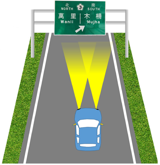
The traffic board on the highway could be lighting by the stray light of the low beams of a vehicle.
Traditional traffic board illumination relies on external light bulbs, and while it has proven effective, innovative designs have emerged to enhance visibility. These novel designs draw inspiration from the technology used in liquid crystal TVs. In these new designs, a liquid crystal layer, equipped with a pair of polarizers and color filters, serves as a passive element for controlling the transmission efficiency of light emitted from the backlight kit. The backlight kit acts as a planar light source, ensuring bright and uniform illumination for liquid crystal display generally12–15. The design of the backlight kit can be roughly categorized into two main approaches. The first approach, known as side-emitting, situates the light source at the side of the backlight light guide, which disperses light as uniformly as possible. The second approach, termed direct view, involves uniformly placing light sources, such as LEDs, on the back of the liquid crystal kit, rendering the backlight light guide unnecessary. Both approaches are applicable to traffic boards, resulting in three distinct illumination methods. A shared characteristic among these three methods is that the maintenance of the lighting system poses a challenge due to its elevated location above the highway.
Another innovative design is the LED dot-matrix sign, which incorporates LEDs directly into the characters, symbols, and borders of the sign. This design enhances the brightness contrast between the signal and the background, thereby extending the visible distance16,17. A noteworthy limitation of this type of traffic sign is that the background remains dark at night, as there is no illumination for it, resulting in a different appearance from daytime to nighttime. Additionally, a common issue with these sign lighting methods is the maintenance challenge, given that the lighting system is typically installed above the highway. Beyond maintenance difficulties, energy efficiency and operating costs are crucial factors to consider, making it essential to explore ways to reduce power consumption to promote sustainability18,19.
In this paper, we will present a study focusing on a remote illumination approach that harnesses the benefits of LED lighting in conjunction with retroreflective film. This remote lighting system is positioned at a distant site, simplifying maintenance procedures. Moreover, it significantly enhances illumination efficiency when compared to conventional methods. We will delve into the characteristics of this innovative design through laboratory measurements and field testing on a superhighway.
Optical Principle
The remote illumination system centers around the use of a retroreflective film (referred to as RTRF) affixed to the surface of the traffic board20. The RTRF is composed of numerous unit cells with a retroreflective structure, designed to efficiently redirect incoming light in a conical manner back toward the light source, as illustrated in Fig. 2. For an extended duration, the RTRF has been positioned on the top surface of traffic boards to primarily reflect stray light emitted by the low beams of passing vehicles. However, this stray light lacks the necessary intensity to provide adequate illumination for driver visibility when the vehicle is situated at a distance of 100 m or beyond. Consequently, supplementary lighting becomes essential. Typically, conventional traffic board illumination does not concentrate the reflected light in a specific direction. As a result, the traffic board, when illuminated, remains visible over a wide field of view, but only a fraction of the reflected light is effectively directed towards the drivers’ eyes. This conventional illumination scheme, therefore, falls short in terms of energy efficiency.
Fig. 2.
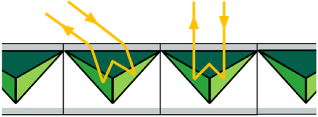
The schematic diagram of the RTRF, where the yellow lines represent the incident and reflected light.
In this paper, we propose an alternative approach involving the use of a spotlight positioned on the side of the driveway to remotely illuminate the traffic board. Given the presence of an RTRF on the top surface of the traffic board, the reflected light is constrained to cover a finite area directed toward the drivers’ eyes, leading to a more energy-efficient solution. However, this approach necessitates consideration of two critical issues.
The first issue is that the spot light must be directional and the divergent angle should be controlled in a finite range to fit with the dimensions of the traffic board. If the lateral dimension of the traffic board is 5 m, the full divergent angle is requested around 3° when the illuminating distance is around 100 m. The solid angle of the projection light must contain sufficient optical flux so that a condition of minimum of the luminous intensity is needed.
The second issue of consideration pertains to the control of the divergent angle (2α) of the reflected light by the RTRF within a defined range. It is imperative that the half divergent angle α exceeds the projection angle (θ), which is the angle between the spot light and the drivers. Failing to ensure a sufficiently large half divergent angle would result in the reflected light not effectively reaching the drivers on the drive way. Conversely, an excessively large half divergent angle would compromise energy efficiency, rendering the approach less effective. To minimize the half divergent angle, an optimal strategy involves situating the spot lights at both sides of the drive way. The design of the spot lights and the optical properties of the RTRF will be comprehensively discussed and analyzed in the following sections.
Spot light design
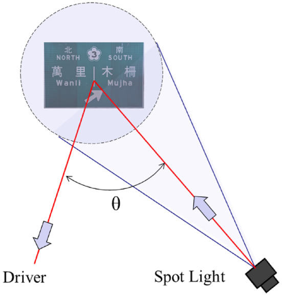
The spot light serves the purpose of projecting light over a substantial distance, ranging from 100 to 300 m. This projection encompasses a full angle that can be as narrow as 3° to 1°, specifically tailored to align with the dimensions of the traffic board, which measures 5 m in width. For the sake of simplicity, we will assume a distance of 100 m between the traffic board and the spot light in our design considerations. The scenario of the driveway for remote illumination is visually depicted in Fig. 3. Before delving into the optical design of the spot light, it is imperative to calculate the required luminance of the traffic board as perceived by a driver who is at the normal of the traffic board. The luminous intensity of the spot light is denoted I and the reflectivity of the traffic board is donated η. If the luminance (B) is assumed constant within the effective light cone reflected by the RFRT, the exitance (M) of the traffic board is written21
 |
1 |
Fig. 3.

The schematic diagram of the illuminance scenario.
where F is the flux on the traffic board projected by the spot light and S/cosθ is the traffic board area. To obtain the luminance of the illuminated traffic board, Eq. (1) can be rewritten
 |
2 |
where L is the distance between the observer and the spot light, and I = dFL2/dS. The luminance in the regulation of Illuminating Engineering Society of North America is suggested up to 80 nits22, and is lower than 200 nits in some other regulations or regions. If we chose to set the luminance of 80 nits at the white area of the traffic board for the driver, while η is set 75%, L is set 100 m, the width of the roadway is set 12 m, θ is set 3.5°, α is set 4°23, and the luminous intensity I of the spot light is calculated around 16,336 cd. If the traffic board width is set 5 m, the spot light’s full divergent angle must be larger than 2.86°. These two values form the design base of the spot light and the RTRF.
To enhance the luminous efficacy of the spot light, our choice of the light source centered on white LEDs, renowned for their impressive luminous efficacy. High-power white LEDs typically offer a luminous efficacy as remarkable as 150 lm/W24. Specifically, the selected white LED belongs to the Cree XPE series25, as depicted in Fig. 4, with emitting dimensions of 1 mm×1 mm of a small etendue21,26,27. It operates at a maximum injection current of 1 A, which corresponds to an output of approximately 3 W. The LED’s dome lens has a diameter of around 2.5 mm, resulting in a far-field distance of approximately 25 mm28.
Fig. 4.

The geometry of Cree-XPE, a a photo, b the side-view structure, and c the silicone dome.
We meticulously crafted a precise model of the light source, drawing upon a mid-field model with the top surface of the yellow phosphor configured as a Lambertian emitter. The simulation results, as well as the corresponding experimental measurements, are presented in Fig. 5. Notably, the similarity determined by the Normalized Cross Correlation (NCC) reached an impressive 99.7% at various distances between the light source and the detector, namely 15 mm, 20 mm, and 50 mm. This outstanding NCC value underscores the accuracy of the light source model29, positioning it as a reliable foundation for the optical design of the spot light.
Fig. 5.

The simulation (black line) and the corresponding measurement (red line) at the distance of a 15 mm, b 20 mm, and c 50 mm.
To achieve a higher intensity while minimizing injection power, the primary objective in optical design is to effectively collimate all the light emitted by the LED. Typically, a common approach involves the use of a Total Internal Reflection (TIR) lens30,31, which can collimate light by utilizing a reflector with total internal reflection properties and a lens oriented in the normal direction32. However, in order to further narrow the divergence of the collimated light, it’s imperative that the dimensions of the TIR lens are sufficiently large. This requirement poses a challenge for traditional TIR lenses. As a result, we’ve devised a hybrid optical structure that combines a reflector and a lens, enabling us to enlarge the dimensions of the reflector to a suitable level. The lens is affixed to a bridge carrier located in front of the reflector, as illustrated in Fig. 6. Additionally, open stripe structures have been incorporated into the two side walls of the reflector to facilitate the adjustability of the bridge carrier, allowing for fine-tuning of the spot light’s divergent angle. This optical design proves invaluable in tailoring the projection light’s divergence to align precisely with the illumination area of the traffic board.
Fig. 6.

a The geometry of the lens and the reflector, b the dimensions, and c the complete set.
The paraboloid reflector was meticulously coated with a metal film, achieving an impressive reflectivity of approximately 80%. The white LED was precisely positioned at the shared focal point of the paraboloid reflector and the top-positioned lens. Notably, when the lens was adjusted closer to the white LED, the lens holder would effectively block the light incident on the reflector, allowing for precise control over the divergent angle of the spot light. The far-field spotlight pattern and its angular distribution are graphically presented in Fig. 7. Here, it’s evident that the Full Width Half Maximum (FWHM) angle measured a mere 2.3°, while the luminous intensity reached a remarkable 83,521 cd. Figure 8 showcases an actual manufactured spot light, and the corresponding experimental measurements demonstrated a slightly increased FWHM angle of 4.4° horizontally and 4.0° vertically. The maximum luminous intensity recorded was around 23,500 cd. It’s worth noting that the larger divergence of the spot light and the resulting reduction in luminous intensity can be attributed to minor imperfections introduced during the manufacturing process. Nevertheless, the measured luminous intensity by the spot light remains sufficiently high for advancing to the next phases of experimentation, both in the laboratory and in real-world field testing on a superhighway.
Fig. 7.

a The far-field pattern, and b the simulated luminous intensity vs. viewing angle.
Fig. 8.

a The sample of the reflector, b the lens, c a photo of the spot light, d the far-field light pattern, and e the spotlight fixture with dimensions of 40 cm×40 cm used in the field test.
Optimization of the RTRF
The RTRF serves as the linchpin of this study. While the RTRF is sourced from 3 M micro-prism reflector33, we currently lack detailed specifications for it. Therefore, our initial focus was on understanding the reflective characteristics of the RTRF. To simplify our experimental measurements, we designed a scaled-down model, akin to a “baby” traffic miniature model with dimensions of 85 cm × 55 cm, which is 1/40 of the traffic board of 510 cm × 330 cm in Taiwan’s superhighways. Remarkably, the RTRF used in this miniature model was identical to that used on the full-scale superhighway boards.
Our experimental setup is depicted in Fig. 9a, wherein a spot light was employed to illuminate the sample board, and we utilized a luminance camera to capture the luminance distribution across the board, and the luminance distribution is shown in Fig. 9b. Recognizing that different locations on the board would have varying reflectivity due to different colors, we selected six distinct points at the green area for characterizing the RTRF. The outcome of these measurements is presented in Fig. 9c, showcasing the luminance as the spot light was positioned at various incident angles on the miniature model. Notably, the luminance at the normal direction was too intense to be accurately measured. However, the central focus of our measurement was the angular tolerance. From these measurements, we ascertained that the divergence angle of the RTRF fell within the range of less than ± 1° centered around the reverse direction of the projection light even the miniature model was tilted at 45°, both in horizontal and vertical directions. Evidently, this angular range was too narrow. To align with this divergence angle, the projection distance would need to exceed 280 m for a traffic board with a width of 5 m.
Fig. 9.

a The experiment setup, b the luminance image of the illuminated miniature model, c-1–c-6 the measured luminance vs. viewing angle at the points corresponding to the indication on the model as in (b), where black : normal incidence; red : tilting 45° horizontally; blue : tilting 45° vertically.
Two principal approaches can be employed to expand this divergence angle. The first method involves increasing the divergence angle of the spot light but the energy efficiency will dramatically decrease, while the second method focuses on enhancing the roughness of the RTRF. We proposed the latter method, which involves attaching a light diffuser onto the RTRF. The thickness of the diffusion film is 60 μm, and the transmittance is 61.4%. The angular distribution of the intensity of the scattered light for the incident collimating beam was measured around 10°, as shown in Fig. 10a. Figure 10b shows a traffic board with three zone of different coverage ratios of the diffuser, where zero is on left, 100% in in the middle, and 50% is on the right. Figure 10c portrays our experimental measurements of the angular-dependent luminance of the reflected light from the RTRF covered with a diffuser film at 100% coverage. While the luminance exhibited a decrease, the FWHM angle expanded to over ± 5°. Consequently, the reflective angle of RTRF with full diffuser coverage was dominant by the diffuser, but it did not lose the directionality in the reflective property.
Fig. 10.

a The angular distribution of the scattering intensity of the diffuser. b The miniature model was covered by a diffuser film of an area of 100% (middle), and 50% (left); c the measured luminance vs. viewing angle when the RTRF was fully covered with a diffuser, and it shows the reflective angle was dominant by the diffuser.
Figure 11 presents an experiment conducted to discern the relationship between brightness and projection angle. In this setup, the camera and spot light were positioned 30 m from the miniature model, while the projection angle was adjusted. Without the diffuser, brightness exhibited a pronounced variation as the projection angle increased. However, with the diffuser, this variation became much more gradual. When the viewing angle deviates from the normal, we can find that the luminance of the full-coverage zone was higher than the zone of the original surface. It means that the diffuser can extend the viewing angle effectively. With the diffuser featuring partial coverage, the variation in brightness could be effectively controlled and balanced, provided the coverage ratio was aptly adjusted.
Fig. 11.

The brightness variation at the three segments of the miniature model when the projection angle changed.
To assess the impact of diffuser coverage on visibility during daytime, we conducted an experiment under various sky conditions, including clear sky, light cloud, and heavy cloud34. The results are presented in Fig. 12, where the numbers indicate the luminance on the white words and the uniform green background across the three diffuser-coverage zones. To further analyze the effect, we calculated the contrast ratio between the two measured values, as shown in Table 1. Two key findings emerged from this analysis. First, the contrast ratio remained relatively consistent across different sky conditions. Second, the measured luminance levels stayed within a limited range. Therefore, we conclude that diffuser coverage does not significantly impact a driver’s visual perception of the traffic board.
Fig. 12.

a Clear sky : ground illuminance = 113,000 lx at 11:51(Jul. 22, 2024); b Clear sky: ground illuminance = 41,000 lx at 15:36 (Jul. 15, 2024); c Light cloud: ground illuminance = 40,000 lx at 12:20, (Jul. 16, 2024); d Heavy cloud : ground illuminance = 20,000 lx at 13:23 (Jul. 19, 2024).
Table 1.
The calculated contrast for the three diffuser-coverage zones under different sky conditions.

Field testing
The testing process was divided into two distinct phases. The first phase involved testing the miniature model within the confines of our campus, while the second phase was dedicated to a proof of concept conducted on an actual superhighway. In the initial phase, the miniature model was positioned 5.3 m above the ground within a dedicated structure. To mitigate the influence of ambient light, we employed a spot light array with a comparable divergent angle, coupled with an injection power of approximately 65 watts, to illuminate the miniature model. The spotlight fixture used in the experiment had a luminous flux of 5,200 lm. A light diffuser was applied to the fixture to project a wide spot onto the miniature model, ensuring uniform illuminance across the model, measured at 76 lx. The spotlight array was positioned 30 m from the miniature model, a distance sufficient to be in the far-field regime, allowing for accurate measurements. A luminance camera was also placed 30 m away, aligned perpendicularly to the miniature board. During the experiment, the spotlight was laterally shifted to adjust the projection angle to 0°, 2.05°, 3.98°, 5.90°, and 7.81°, respectively. Figure 13; Table 2 provide a comprehensive summary of our luminance measurements as a function of projection angle. In the field test, we observed that as the viewing angle increased, the luminance in zone 2 or zone 3 could be higher than in zone 1. The contrast ratios between the white text and the green background remained consistent, ranging between 2.5 and 5.
Fig. 13.

a The miniature board in the experiment. b1–f1 The photos of the illuminated miniature board for the projection angles of 0°, 2.05°, 3.98°, 5.90° and 7.81°, respectively. b2–f2 The corresponding spatial distribution of luminance by the luminance camera. The red dots are the measurement points listed in Table 2.
Table 2.
The measured luminance of the miniature board in the three zones under different projection angles.

To assess the energy-saving capabilities of our proposed scheme, we introduced a metric called luminance efficacy, defined as the ratio of measured luminance to the injection power of the spotlight fixture, expressed in units of nit/W. It’s important to note that luminance efficacy is influenced by the reflective properties of the RTRF and design of the spotlight. In our experiment, the illuminance on a miniature model measuring 0.85 m × 0.55 m was 76 lx, and the flux on the miniature model was calculated to be 35.5 lm. Given that the area of the real traffic board is 40 times larger than that of the miniature model, the total flux required to achieve the same luminance level in the full-scale measurement is 1,420 lm.
To determine the necessary power for the lighting fixture, we considered both the area of the traffic board and the projection area of the spotlight fixture. To examine the flux ratio on the target resulting from light projection, we defined an optical utilization factor (OUF)26, which is the ratio of the flux received by the traffic board to the total flux emitted by the spotlight fixture. Figure 14 provides a schematic diagram illustrating the OUF through a geometrical factor, showing that only the central portion of the projected light spot covered the traffic board. For our calculations of luminance efficacy, we set the OUF value at 50%.
Fig. 14.
The geometrical factor of the spot light projection in deciding OUF.
The luminous efficacy of the spotlight fixture was measured at 80 lm/W. Based on this, the calculated injection power required to achieve the measured luminance was 35.5 W. We then calculated the luminance efficacy of the miniature model across three zones as a function of the projection angle, as shown in Fig. 15. Considering that the spotlight fixture is intended to be installed 100 m or more from the traffic board, the projection angle would be within 3°. Under these conditions, the luminance efficacy for 50% diffuser coverage reaches approximately 7.5 nit/W, meaning that only 40 W is needed to produce 300 nits for the traffic board of 510 cm × 330 cm. In comparison with traditional lighting on the traffic board, this demonstrates a highly effective method for saving energy of more than 75%.
Fig. 15.

The calculated luminance efficacy vs. the projection angle. The yellow dots and solid lines are for white word and the green dots and dash lines are for green background.
Conducting field tests on a superhighway can be a challenging and perilous endeavor. Therefore, our approach involved capturing photographs to validate the concept of our new method. We embarked on a journey to the sidewalk of Taiwan’s #1 superhighway, located in Taoyuan city. Positioned above the highway were three traffic boards, each employing different lighting techniques that we had designed back in 2015. The left board featured segmental backlighting, the middle one employed direct-view backlighting, and the right board relied on external illumination with LEDs at 170 W, as depicted in Fig. 16.
Fig. 16.

a The testing in a super highway for proof of concept. Green board : left, backlight for white words only; middle, direct-view backlight; right, traditional external-lighting. b The traffic boards in the original condition. c With spotlight illumination, and dramatic enhancement on the luminance on the left green board can be observed.
In Fig. 16b, c, we could observe the effect by the illumination of the spotlight. The measured luminance at the sites marked with red arrows were 3.3 nits before and 31.5 nits after illuminated by the spot light at 3 W. Evidently, the spot light significantly enhanced the brightness of all three traffic boards, rendering the characters and indicators on these boards much clearer and easier to identify. The field test at the superhighway is aimed to confirm the effectiveness of the proposed method.
Conclusion
In this paper, we present a pioneering approach to lighting traffic boards along a superhighway. Our innovative method involves illuminating traffic boards equipped with retroreflector film using remote spotlights strategically positioned at the side of the roadway. This setup significantly simplifies the maintenance of the lighting system. Since the lighting is achieved through remote illumination, it is crucial to ensure that the divergence angle of the spotlights is appropriately adjusted to match the size of the boards and their distance from the source of projection.
To achieve the desired spotlight configuration, we developed a hybrid optical system comprising a paraboloid reflector and a lens mounted on a bridge holder on the mirror’s top surface. This spotlight is used to determine the divergence angle of the RTRF. It was found that the initial divergence angle was too narrow, requiring the projection angle between the traffic board and the spotlight to be less than 1o, with a minimum projection distance of 280 m, and precise projection angle alignment. To enhance the tolerance of the projection angle, we propose two key strategies. First, by shortening the projection distance and simultaneously increasing the spotlight’s divergence angle, we can achieve greater accuracy in the projection angle. Second, to widen the divergence angle of the RTRF, we suggest affixing a light diffuser film onto the RTRF. The coverage area ratio of the diffuser film can be adjusted to select the desired divergence angle for the reflected light.
The experimental measurements revealed that the half divergent angle of the RTRF was 3°, 5,5°, and 7° for the original, full-coverage diffuser film, and half-coverage diffuser film, respectively, while maintaining a projection luminance efficacy of 7.5 nit/W with an OUF of 50%. With a target illuminance of 300 nits at the white word on a traffic board of 510 cm × 330 cm, the power consumption of the spot light is calculated 40 W, which saves more than 75% energy compared with traditional lighting approaches.
Conducting field tests on a superhighway can be challenging, so we opted to use a spot light to illuminate specific traffic boards on the superhighway. This underscores the effectiveness of remote projection using a spotlight, as it does not only save more than 75% of energy but also simplifies maintenance requirements, essentially opening a window to a more efficient and manageable lighting solution. This novel lighting approach offers an efficient and effective solution for illuminating traffic boards on superhighways, optimizing visibility and safety for drivers while simplifying maintenance and adjustment requirements.
Acknowledgements
The author would like to thank Breault Research Organization (BRO), Inc. for sponsoring the ASAP software program. In addition, the authors would like to thank BENEX for helping in manufacturing the spot light. The research was sponsored by the National Council of Science and Technology in Taiwan with grant no. MOST 111-2218-E-008-004 –MBK and MOST 111-2221-E-008 -028 -MY3.
Author contributions
C.C.S. was the team leader, proposed the idea, designed/participated the experiments and made the major calculation; C.S.W. conducted the partial experiments and the corresponding calculation; S.K.L. conducted partial experiments; T.X.L. joined partial experiments; J.Y.C. designed the spot light; T.H.Y. and Y.W.Y. joined the technical discussion. All authors reviewed the manuscript.
Data availability
The datasets used and/or analyzed during the current study available from the corresponding author on reasonable request.
Declarations
Competing interests
The authors declare no competing interests.
Footnotes
Publisher’s note
Springer Nature remains neutral with regard to jurisdictional claims in published maps and institutional affiliations.
References
- 1.Dewar, R. E., Ells, J. G. & Mundy, G. Reaction time as an index of traffic sign perception. J. Hum. Factors Ergon. Soc. 18, 381–391 (1976). [DOI] [PubMed] [Google Scholar]
- 2.Long, G. M. & Kearns, D. F. Visibility of text and icon highway signs under dynamic viewing conditions. J. Hum. Factors Ergon. Soc. 38, 690–701 (1996). [Google Scholar]
- 3.Bullough, J. D. et al. Response to simulated traffic signals using light-emitting diode and incandescent sources. Transp. Res. Rec. 1724, 39–46 (2000). [Google Scholar]
- 4.Schmidt-Clausen, H. J., Th, J. & Bindels, H. Assessment of discomfort glare in motor vehicle lighting. Lighting Res. Technol. 6, 79–88 (1974). [Google Scholar]
- 5.UNECE. Addenda to the 1958 Agreement (Regulations 101–120), https://unece.org/transport/vehicle-regulations-wp29/standards/addenda-1958-agreement-regulations-101-120
- 6.Hsieh, C., Li, Y. & Hung, C. Modular design of the LED vehicle projector headlamp system. Appl. Opt. 52, 5221–5229 (2013). [DOI] [PubMed] [Google Scholar]
- 7.Ge, A. et al. High-energy-efficiency optical system for an LED-based headlamp architecture. Appl. Opt. 52, 8318–8323 (2013). [DOI] [PubMed] [Google Scholar]
- 8.Wang, H., Wang, X., Li, Y. & Ge, P. Design of a newly projected light-emitting diode low-beam headlamp based on microlenses. Appl. Opt. 54, 1794–1801 (2015). [Google Scholar]
- 9.Nilsen, R. B. & Lu, X. J. Retroreflection technology, Proc. SPIE 5616, 47–60 (2004).
- 10.Snyder, J. J. Paraxial ray analysis of a cat’s-eye retroreflector. Appl. Opt. 14, 1825–1828 (1975). [DOI] [PubMed] [Google Scholar]
- 11.Burgess, G., Shortis, M. R., Scott, P. & Photographic assessment of retroreflective film properties. ISPRS J. Photogramm. Remote Sens. 66, 743–750 (2011). [Google Scholar]
- 12.Lee, X. H., Lin, C. C., Chang, Y. Y., Chen, H. X. & Sun, C. C. Power management of direct-view LED backlight for liquid crystal display. Opt. Laser Technol. 46, 142–144 (2013). [Google Scholar]
- 13.Qin, Z., Wang, K., Chen, F., Luo, X. & Liu, S. Analysis of condition for uniform lighting generated by array of light emitting diodes with large view angle. Opt. Express. 18, 17460–17476 (2010). [DOI] [PubMed] [Google Scholar]
- 14.Wang, Y. J., Ouyang, S. H., Chao, W. C., Lu, J. G. & Shieh, H. P. D. High directional backlight using an integrated light guide plate. Opt. Express. 23, 1567–1575 (2015). [DOI] [PubMed] [Google Scholar]
- 15.Mellette, W. M., Schuster, G. M., Glenn, M. & Ford, J. E. Planar waveguide LED illuminator with controlled directionality and divergence. Opt. Express. 22, A742–A758 (2014). [DOI] [PubMed] [Google Scholar]
- 16.Porathe, T. & Strand, L. Which sign is more visible? Measuring the visibility of traffic signs through the conspicuity index method. Eur. Transp. Res. Rev. 3, 35–45 (2011). [Google Scholar]
- 17.Rista, E. & Fitzpatrick, K. Comparison of LED-Embedded pedestrian crossing signs with rectangular Rapid Flashing beacons and Pedestrian Hybrid beacons. Transp. Res. Rec. 2674, 856–866 (2020). [Google Scholar]
- 18.Knobloch, F. & Braunschweig, N. A traffic-aware moving light system featuring optimal energy efficiency. IEEE Sens. J. 17, 7731–7740 (2017). [Google Scholar]
- 19.Westbrook, M. & Rasdorf, W. LED Traffic Signal Repair and replacement practices. Sustainability. 15, 808 (2023). [Google Scholar]
- 20.Su, W. & Li, D. Retro-reflectivity and night visibility of road traffic signs. J. Highway Transp. Res. Dev. 4, 97–102 (2010). [Google Scholar]
- 21.Palmer, J. M. & Grant, B. G. The Art of Radiometry (SPIE, 2009).
- 22.Illuminating Engineering Society of North America (IESNA), Roadway Sign Lighting, Recommended Practice RP-19-01. New York, (2001).
- 23.Recarte, M. A. & Nunes, L. M. Mental workload while driving: effects on visual search, discrimination, and decision making. J. Exp. Psychol. 9, 119–137 (2003). [DOI] [PubMed] [Google Scholar]
- 24.LEDs, M. A. G. A. Z. I. N. E. Cree R&D achieves 161 lm/W for high-power LED, (2008) https://www.ledsmagazine.com/manufacturing-services-testing/substrates-wafers/article/16697819/cree-rd-achieves-161-lmw-for-highpower-led
- 25.CREE LED, Cree, L. E. D. & Products https://www.cree-led.com/products/leds/xlamp/xp-xt/
- 26.Sun, C. C. & Lee, T. X. Optical Design for LED Solid State Lighting: A Guide (IOP, 2022).
- 27.Sun, C. C. et al. Review of optical design for vehicle forward lighting based on white LEDs. Opt. Eng. 60, 091501 (2021). [Google Scholar]
- 28.Mahajan, V. N. Optical Imaging and Aberrations: Ray Geometrical Optics (SPIE, 1998).
- 29.Sun, C. C., Lee, T. X., Ma, S. H., Lee, Y. L. & Huang, S. M. Precise optical modeling for LED lighting verified by cross correlation in the midfield region. Opt. Lett. 31, 2193–2195 (2006). [DOI] [PubMed] [Google Scholar]
- 30.Welford, W. T. High Collection Nonimaging Optics (Academic, SanDiego, 1989).
- 31.Winston, R. Nonimaging Optics (Academic, SanDiego, 2005).
- 32.Wu, C. S. et al. Design of an LED spot light system with a Projection Distance of 10 km. Crystals. 9, 524 (2019). [Google Scholar]
- 33.Science, M. & 3 M Reflective Sheeting., https://www.3m.com/3M/en_US/p/c/films-sheeting/reflective-sheeting/
- 34.Sun, C. et al. Hybrid high-concentration photovoltaic system designed for different weather conditions. Sci. Rep. 13, 5206 (2023). [DOI] [PMC free article] [PubMed] [Google Scholar]
Associated Data
This section collects any data citations, data availability statements, or supplementary materials included in this article.
Data Availability Statement
The datasets used and/or analyzed during the current study available from the corresponding author on reasonable request.