Abstract
We present a study of self-healing mechanisms including their kinetics and thermodynamics in nickel coatings. The bioinspired self-healing coating is designed to enhance the durability of structural metal components exposed to harsh conditions. Microcapsules, reminiscent of natural healing reservoirs, were synthesized via in situ polymerization in an oil-in-water emulsion to encapsulate linseed oil, a healing agent, within poly(urea-formaldehyde) (PUF) shells. Nickel coatings incorporating PUF shell microcapsules were electrodeposited on mild steel substrates to assess their effectiveness in self-healing, mimicking nature's ability to provide on-demand healing. Comprehensive characterization of the microcapsules and coating was performed using techniques including Optical Microscopy (OM), Scanning Electron Microscopy (SEM), Energy Dispersive X-ray Spectroscopy (EDS), and Thermogravimetric Analysis (TGA). The self-healing performance of the coating was evaluated using SEM and EDS after scratches simulating damage were made on the surfaces of the samples. Corrosion resistance and self-healing ability were evaluated through an immersion test, and additional corrosion resistance tests such as Open Circuit Potential (OCP) and Linear Polarization (LP) were conducted. The results indicate that the nickel coating containing PUF shell microcapsules confers corrosion resistance to the substrate and, upon damage to that coating, induces a self-healing response analogous to natural systems, highlighting the potential of bioinspired designs in advanced material solutions.
A self-healing anticorrosive nickel coating using poly(urea-formaldehyde) (PUF) shell microcapsules containing linseed oil triggers a self-healing response to damage similar to mechanisms observed in nature.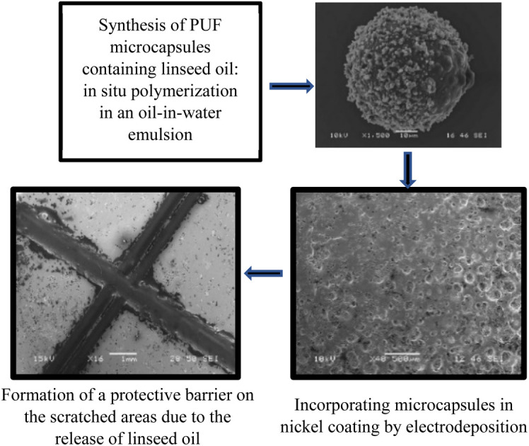
1. Introduction
The exceptional mechanical properties of metals make them a popular choice for structural and engineering applications, given their adaptability to meet specific needs.1 However, they are prone to corrosion, wear, and mechanical failures, resulting in economic losses and even loss of human lives.2–4 The National Association of Corrosion Engineers (NACE) International's 2016 study on corrosion estimated the global cost of corrosion at $2.5 trillion (3.4% of global GDP).5 Though corrosion cannot be eliminated, corrosion-related costs could be saved up to 30% by implementing corrosion management techniques such as painting and/or coating.6
Coatings are the most common and efficient method used to protect metals from corrosive attacks.7 Self-healing coatings provide a promising and cost-effective solution to traditional coatings, effectively addressing the issue of metal corrosion.8–14 Self-healing in general and at the surface of metals involves many fundamental physico-chemical problems.15–17 Thus, it has been suggested to apply the approach of non-equilibrium thermodynamics to relate the structure of a self-healing composite material to its healing properties.16,17 Self-healing coatings can be designed to respond to external stimulation (such as temperature, light, etc.) or they can act autonomously at the site of damage.11,18,19 Self-healing effects in coatings can be intrinsic or extrinsic.12,20
Healing is a natural capability found in the diverse populations of plants and animals, developed over time through the process of evolution.21 Self-healing based on biological capsules is a remarkable natural phenomenon that has inspired synthetic applications.22 In nature, this process is exemplified by the use of latex, a complex emulsion containing proteins, alkaloids, starches, oils, resins, and gums, in plants like Hevea brasiliensis and Ficus benjamina.23,24 Latex serves as a healing agent encapsulated under high pressure in laticifers, specialized cells in the plants.25,26 When these plants suffer physical damage, the latex is exuded due to pressure differences, releasing proteins which induce coagulation and seal wounds.22 The synthetic replication involves encapsulating reactive healing chemicals in microcapsules, which are then embedded in various materials. Upon damage, these capsules rupture, releasing their contents which then react to repair the material. The success of this technique is evident in applications like self-healing epoxies,27 polymers,2 concretes,28 and epoxy and polymer coatings,2,29–31 where the embedded microcapsules release their contents upon cracking, thus initiating a healing process.
Vascular and capsules/balloons-based self-healing coatings are the most common extrinsic autonomous self-healing coatings that are used to protect metals from corrosion.32–34 The use of capsules/balloons is the most promising method to achieve self-healing in coatings.2 Most research efforts in self-healing coatings to date have been largely based on polymeric matrix loaded with micro/nanocapsules with very little discussion of metallic-based self-healing coatings loaded with micro/nanocapsules.2,10,24,35 Research on the incorporation of nano/microcapsules in metallic coatings to enhance corrosion resistance, self-healing capabilities, and tribological properties has been limited.36–39 In one study, microcapsules composed of PUF shell and lubricating oil core were synthesized by in situ interfacial polymerization and incorporated into a nickel matrix on brass and steel through electrodeposition, resulting in coatings with higher microhardness, lower surface roughness, and improved wear resistance compared to pristine nickel coatings.40 In another study, nickel coatings with polyterephthalamide and polyamide microcapsules containing a santosol core, applied uniformly using a rotating electrode, demonstrated potential in reducing wear rates and friction coefficients.41 A patent has been issued for the concept of depositing metallic shell microcapsules containing organic or inorganic corrosion inhibitors on a metallic matrix, including various metals and alloys, by electroplating, electroless deposition, or thermal spraying.9 However, this concept has not been experimentally demonstrated. Another patent discussed the synthesis of polyamide shell microcapsules containing santosol oil and their incorporation in nickel and copper matrices by electroplating, resulting in drastically improved friction coefficient and wear resistance.42 Recently, microcapsules with hybrid shells of polyurea-formaldehyde/SiO2 containing linseed oil were incorporated into a Ni–Co coating electrodeposited on mild steel plates to investigate their anti-corrosion properties43 and self-healing properties.18 The corrosion study showed that embedding the capsules in the coating significantly improved its resistance to corrosion compared to the neat Ni–Co coating. However, no studies have been conducted on the effect of damage or scratches on the coating's anti-corrosion properties, and the self-healing properties have not been well demonstrated.
The migration of charged particles through electrophoresis is critical in the electroplating process of self-healing coatings. It is hypothesized that microcapsules with positively charged surfaces facilitate their co-deposition with metal ions at increased speeds, where the deposition rate is influenced by the size of the capsules.10 A metallic matrix loaded with micro/nanocapsules filled with a healing agent can be applied to metal surfaces prone to corrosion. If the coating is damaged, cracked, or scratched, the micro/nanocapsules break open, releasing the healing agent into the affected area through capillary action. The healing agent then polymerizes upon contact with atmospheric oxygen, forming a thin film that fills the defect cavity and ‘heals’ the crack. We suggest a bioinspired21 anticorrosive self-healing coating to protect metal substrates against corrosion. Despite the progress in self-healing polymeric coatings, a significant research gap remains in the development and evaluation of metallic-based self-healing coatings. Metallic coatings, particularly self-healing nickel coatings, have not been studied for their ability to simultaneously provide corrosion protection and autonomously repair mechanical damage. This study addresses this gap by developing and characterizing bioinspired nickel coatings that incorporate poly(urea-formaldehyde) (PUF) microcapsules containing linseed oil. The purpose of these nickel-microcapsule coatings is to improve the durability of structural metal components in corrosive environments, such as those encountered in the marine, automotive, and aerospace industries. The physico-chemical study of the nickel coating containing PUF shell microcapsules reveals that the coating not only significantly improves the substrate's resistance to corrosion but also displays a self-healing ability when damaged, similar to mechanisms observed in natural systems. This underscores the promising potential of bioinspired approaches in the advancement of material solutions, demonstrating how such innovative designs can lead to more resilient and self-sustaining materials.
2. Experimental section
The following experimental procedure was used. PUF shell microcapsules containing Linseed Oil (LO) were synthesized via in situ polymerization in an oil in water (o/w) emulsion. The nickel self-healing coating containing PUF shell microcapsules (referred to as Ni-PUF shell self-healing coating) was then electrodeposited on mild steel (1018) substrates. The synthesized microcapsules were characterized by Optical Microscopy (OM), Scanning Electron Microscopy (SEM), Energy Dispersive X-ray Spectroscopy (EDS), Laser Diffraction Particle Size Analysis (LDPSA), Differential Scanning Calorimetry (DSC), and Thermogravimetric Analysis (TGA). Optical microscopy, confocal microscopy (CM), X-ray diffraction (XRD), SEM, and EDS analysis were conducted for the synthesized self-healing coatings. Finally, self-healing performance of the coating was evaluated via SEM and EDS after making scratches on the surfaces of the samples. The corrosion resistance and self-healing effectiveness of the scratched coatings were examined through an immersion test following ASTM G31 (ref. 44) in a 3.5% NaCl solution. Further to the study, additional tests focusing on Corrosion Resistance Characterization, specifically Open Circuit Potential (OCP) and Linear Polarization (LP), were conducted to evaluate the coating's effectiveness against corrosion.
2.1. Materials
Polyvinyl alcohol (PVA) (5% w/v) solution, resorcinol, sodium dodecyl sulfate (SDS) (1% w/v), and urea were purchased from Neon Commercial LTDA. All reagents were analytical grade. Ammonium chloride, xylene, hydrochloric acid, 37 wt% formaldehyde aqueous solution, nickel sulfate hexahydrate (NiSO4·6H2O), saccharin (C7H5NO3S), and boric acid (H3BO3) were purchased from Sigma-Aldrich company. Extra virgin linseed oil (LO) was obtained from Wheat Flowers CISBRA LTDA. Low carbon (Grade 1018) ground flat steel was purchased from Speedy Metals to use as the substrate for coating.
2.2. Microcapsules synthesis
Microcapsules with a PUF shell and an LO core were synthesized via in situ polymerization in an oil-in-water emulsion, following the methods developed by Brown et al. and Blaiszik et al.45,46 The synthesis process was modified to achieve the desired size, shape, and morphology of the microcapsules. Urea, formaldehyde, resorcinol, and ammonium chloride are the shell-forming compounds; PVA and SDS are emulsion stabilizers; linseed oil is the core material, and hydrochloric acid is the pH adjustor. The synthesis process is commercially viable due to its versatility, scalability, ease of use, and affordability of materials and equipment, as well as its control over capsule size and shell thickness.47–50 The flowchart of the synthesis procedure of PUF shell microcapsules is given in Fig. S1 (in ESI†). 150 mL of deionized water, 6 mL of a PVA solution (5% w/v), and 10 mL of an SDS solution (1% w/v) were stirred in a 1000 mL glass beaker using a magnetic stirrer. The glass beaker was fully submerged in a temperature-controlled water bath during the stirring process. While stirring, 3.00 g of urea, 0.30 g of resorcinol, and 0.30 g of ammonium chloride were introduced to the mixture, followed by the addition of 32 g of LO. The LO was slowly stirred for 6 minutes for stabilization, and the mixture was subjected to vigorous stirring at a speed of 600 rpm for 1 hour to ensure thorough emulsification. After that, the pH level of the mixture was measured and brought to 3.5 with a 3.6 wt% HCl solution. Additionally, 7.6 g of formaldehyde solution was incorporated into the mixture. The temperature was then elevated to 55 °C, and a second round of stirring at 600 rpm was conducted for approximately 4 hours. The synthesized microcapsules were separated from the liquid suspension using filter papers in two steps. In first step, Whatman 1441-125 41 Ashless Quantitative Filter Paper with pore size of 20–25 microns was used. In the second step, Whatman 1441-125 42 Ashless Quantitative Filter Paper with pore size of 2.5 microns was used. The microcapsules were repeatedly washed with deionized water and xylene to eliminate any remaining oil from damaged capsules. Xylene can dissolve the leaked LO that prevents the microcapsules to stick together.51
2.3. Microcapsules characterization
Synthesized micro-capsules were characterized by Optical Microscopy (Amscope trinocular optical microscope and Zeiss Stemi 2000c stereo microscope), SEM/EDS (JEOL 6460LV), LDPSA (Malvern Mastersizer 3000), DSC (TA Instruments Q200), and TGA (Netzsch 449 F1) analysis. Microcapsules shape, morphology, and size were analyzed through images from the SEM. The samples were coated with a very fine layer of gold (Au) and palladium (Pd) to make them electrically conductive to facilitate SEM imaging. Optical microscopy was used to study the emulsion of oil droplets and synthesized microcapsules floating in the distilled water. EDS was used to study the composition of microcapsules.
2.4. Coating preparation with microcapsules
Ni-PUF shell microcapsule coating was electrodeposited on mild steel substrates following the procedures outlined below.
• 250 g L−1 of nickel sulfate hexahydrate (NiSO4·6H2O) was added to distilled water in a 250 mL glass beaker.
• 30 g L−1 of boric acid (H3BO3) was added to the solution as a buffer.
• The electrodeposition process was performed on a 2.54 cm × 2.54 cm × 1.54 mm mild steel substrate (total area of roughly 14.5 cm2), employing a DC current of 362 mA for an approximate current density of 25 mA cm−2. The constant current mode of the DC power supply was used to conduct the experiment, with the voltage of the setup being approximately 3.22 volts. The substrate was prepared by following the below procedure:
• The substrate was polished using a polishing machine with Pace Technologies SiC grit paper of standard grits 600, 800, and 1200, followed by 1-micron alumina powder. The substrate was cleaned with soap first; then it was kept in acetone and sonicated for 5 minutes for degreasing. Then it was kept in 3.6% HCl for 30 seconds for surface activation. After each step, the substrate was thoroughly washed and cleaned with distilled water.
• 0.5 g L−1 of saccharin (C7H5NO3S) was added to the bath. It is reported that adding saccharin (C7H5NO3S) to the bath will result in a nano-structured coating that has better corrosion resistance properties.18,43
• 0, 1, 10, 20, or 30 g L−1 microcapsules were added to the bath.
• After the substrate was prepared, it was quickly positioned in the deposition bath as a cathode. Platinized titanium mesh was used as the anode for the experiment.
• The pH of electrolyte was kept at 5 and the temperature of the bath was kept at 40–45 °C for optimum electrodeposition of Ni-PUF shell microcapsules coating. The electrodeposition experiment was run for 120 minutes.
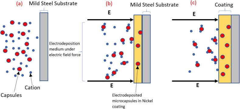
The term “electrodeposition” is being used in this paper in the broader sense to include both electroplating and electrophoretic deposition. It is hypothesized that the co-deposition of metal-microcapsules coating using electrodeposition methods occurs possibly by the following mechanism, as shown in Fig. 1: Initially, the capsules are dispersed in the solution without any external electric field. When an external electric field is applied, bonds are formed between positively charged metal ions and capsule shell materials. The ion-attached capsules move towards the cathode, where they become enveloped by the metallic coating.10,52 Similar research suggests that the microcapsules are successfully incorporated into the nickel matrix probably due to the ability of nickel ions to adsorb on the microcapsules which results in the microcapsules becoming embedded in the coating as the nickel ions are reduced at the cathode.40 Further investigation is required to identify the precise mechanisms that facilitate the co-deposition of metal-microcapsule coatings. Several factors, including bath conductivity, viscosity, stability, particle concentration, size distribution, surface charge density, electrode current density, deposition time, applied voltage, and substrate conductivity, need to be examined to understand their influence on the co-deposition process.53
Fig. 1. Schematic mechanism for the co-deposition of metal-microcapsule coating using electrodeposition methods. The figure illustrates three main stages: (a) the initial condition of the electrodeposition medium before applying direct current, (b) the bonding of metal ions to the microcapsules under the influence of the electric field, and (c) the movement of the capsules and ions towards the cathode.10,52.
The zeta potential of PUF shell microcapsules containing linseed oil was measured with a Brookhaven ZetaPALS Zeta Potential Analyzer. This measurement is crucial because the dispersion stability of the microcapsules depends on the zeta potential. The results illustrated in Fig. S2† indicate that the microcapsules are stable at a pH value of 5, with a zeta potential of less than −29 mV. This stability suggests that at this pH, the microcapsules have sufficient electrostatic repulsion to remain dispersed without aggregating. Additionally, magnetic stirring was maintained at 250 rpm throughout the entire process to ensure an even distribution of the capsules and ions during electrodeposition.
2.5. Electrochemical corrosion test setup configuration
Electrochemical corrosion tests were performed with a BioLogic SP-200 using a 250 mL flat cell and Ag/AgCl reference electrode in a 3.5 wt% NaCl solution. The sample was connected to the cell with a flat copper contact and exposed to the electrolyte using a 1 cm diameter flat gasket mask. Open Circuit Potential (OCP) was averaged over a 30 minute period. The Linear Polarization (LP) sample was scanned from −50 mV to +50 mV (relative to the sample OCP) at a rate of 0.166 mV s−1.
3. Results and discussion
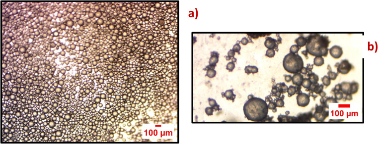
Optical microscopy was used to study the emulsion of oil droplets and the distribution of synthesized microcapsules.45,46,51 It was observed that the size distribution of the emulsion of the oil droplets was uniform. The shells of the microcapsules are stable enough to embed into the nickel coating on the mild steel substrate by electrodeposition method. Fig. 2(a) shows the optical microscope image of the emulsion of LO and Fig. 2(b) shows the optical microscope image of synthesized microcapsules with PUF shells after two hours of reaction time.
Fig. 2. Optical microscope image of (a) emulsion of linseed oil in water (size of the scale bar: 100 μm), (b) synthesized micro-capsules after two hours of reaction time of their constituents (size of the scale bar: 100 μm).
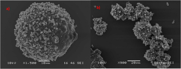
SEM characterization was conducted to study the average size and morphology of the synthesized microcapsules. Microcapsules with uniform size distribution are depicted in Fig. 3, which have LO core and PUF shells. From Fig. 3 and S3† it can be found that microcapsules have a mean size of ∼25 micrometers. The size distribution of the synthesized microcapsules as measured by LDPSA is presented in Fig. S4.† The sizes of synthesized microcapsules range from 15 micrometers to 756 micrometers. The optimal capsule size for self-healing systems ranges from 30 to 600 micrometers.54,55 Reducing the size of the capsules to the nanoscale can significantly improve their performance. This is because they would have more contact with the surrounding material (matrix), allowing them to disperse better. However, smaller capsules have a reduced capacity to store oil, which might impede performance of healing. Thus, it is important to select capsules of the right size that can contain the precise amount of oil necessary for effective healing.51
Fig. 3. SEM micrographs of microcapsules (a) single microcapsule (size of the scale bar: 10 μm), (b) aggregates of microcapsules (size of the scale bar: 20 μm).
SEM micrographs reveal that the microcapsules have rough surfaces and branch-like spots as shown in Fig. S3.† The rough surface of the microcapsules is due to tiny colloidal UF particles that stick together and form a layer around them. This rough outer shell makes the microcapsules have more surface area, like a hook that grabs onto the nickel matrix and helps them stick better. EDS analysis of the microcapsules confirmed that the shell of the microcapsules is made of carbon, nitrogen, and oxygen which are the elemental constituents of PUF. Fig. S5† shows the EDS analysis result of the surface of the synthesized microcapsules.
The TGA graph shown in Fig. S6† illustrates the thermal degradation of PUF shell microcapsules containing LO versus pure unencapsulated LO. The microcapsules show an initial weight loss below 150 °C, likely due to moisture and free formaldehyde evaporation, a process not observed in the stable linseed oil. Both samples remain relatively unchanged until around 300 °C, where a sharp decline in mass indicates decomposition of the microcapsule shell and the onset of linseed oil evaporation. Notably, the slope change around 370 °C for the microcapsules may signify the shell fracture and subsequent linseed oil release. The weight levels off beyond 450 °C, signaling the end of major mass change and leaving behind any non-volatile residue. The unencapsulated LO curve shows the evaporation/boiling of the linseed oil, resulting in little to no residual mass. This behavior, captured in an inert argon atmosphere to prevent oxidation, is crucial for assessing the heat resistance of the microcapsules for their application in self-healing coatings.
The DSC graph, illustrated in Fig. S7,† presents the thermal behavior of PUF shell microcapsules containing LO in comparison with unencapsulated LO. The microcapsules display a significant endothermic peak at 84.6 °C, associated with the evaporation of moisture and free formaldehyde, absent in the pure linseed oil curve. At 156 °C, an exothermic reaction specific to the microcapsules likely indicates residual core material reaction, while the second endothermic peak at 223 °C suggests decomposition of the microcapsule's shell, a transition not observed in linseed oil sample. The exothermic peak at 369 °C observed for the microcapsules, is probably due to the polymerization of the linseed oil core facilitated by urea derivatives from the shell. Additionally, there are several peaks and troughs in the higher temperature range (beyond 300 °C) for both microcapsules and linseed oil, but they are more pronounced in the microcapsules. These could correspond to various chemical reactions, such as further decomposition and potential cross-linking reactions, which are more complex in the microcapsules due to their composite nature. The graph reveals that linseed oil exhibits a simpler thermal profile with fewer transitions, whereas the microcapsules demonstrate a complex series of endothermic and exothermic peaks, reflecting the intricate interactions between their core and shell components.
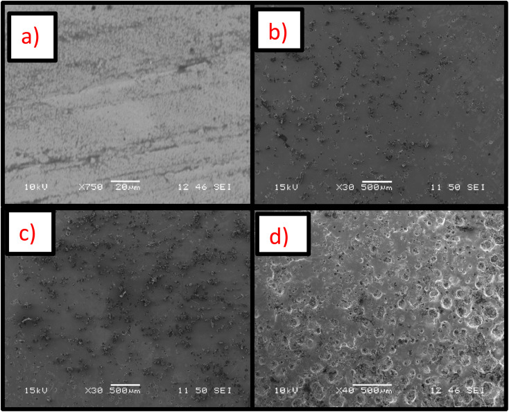
Nickel and Ni-PUF shell microcapsules were electrodeposited on the mild steel substrates. The optical image of the synthesized sample coated with nickel is shown in Fig. S8(a),† and the sample coated with Ni-PUF shell microcapsules coating (the quantity of microcapsules in the coating is 10 g L−1) is shown in Fig. S8(b).† It is observed that the nickel coating on mild steel substrate is yellowish white in color and has a reflective finish. The incorporation of microcapsules to the coating changes the appearance of the coating with black dots becoming visible with the addition of the microcapsules. SEM and EDS characterizations of self-healing coating were conducted to study the distribution, morphology, and compositions of the coatings. Fig. 4 and S9† show the distribution of the microcapsules in the self-healing coatings. Optical and SEM micrographs reveal that microcapsules are uniformly distributed over the surface of the coatings and microcapsules branches act as a hook in the coatings. The optical and SEM micrographs also indicate a gradual increase in the presence of microcapsules on the coating surface with higher concentrations in the electrodeposition bath, showing a more pronounced presence at 30 g L−1 of microcapsules compared to 20 g L−1 and 10 g L−1 concentrations. It is expected that the higher amounts of microcapsules in the coating will enhance the self-healing performance of the coatings. The XRD analysis, as shown in Fig. S10,† confirms the formation of the nickel coating on the substrate, as indicated by the distinct diffraction peaks corresponding to the nickel in both the neat nickel coating and the nickel coating with 20 g L−1 microcapsules. These peaks align with standard values for metallic nickel (PDF 01-088-5735), verifying the crystalline nature of the coatings. The incorporation of microcapsules in the nickel matrix results in a slight reduction in peak intensity and increased peak broadening, which may be due to a decrease in crystallite size or an increase in lattice strain, a typical effect when secondary phases such as microcapsules are embedded in nickel coatings. However, the predominant nickel phase remains unaffected, confirming that the electrodeposited coating retains its essential crystalline structure for providing corrosion resistance and self-healing functionality.
Fig. 4. SEM micrographs of nickel-PUF shell microcapsules self-healing coatings with different microcapsule concentrations: (a) 0 g L−1, (b) 10 g L−1, (c) 20 g L−1, and (d) 30 g L−1 in the bath.
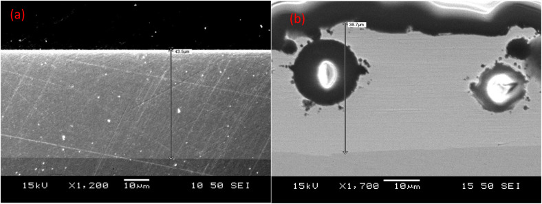
The cross-sections of the nickel coating and the nickel coating with microcapsules are shown in Fig. 5(a) and (b). The thickness of all coatings was found to be around 40 μm. The figures clearly illustrate that the deposition of nickel on the substrate is compact, while the incorporation of microcapsules in the nickel coating introduces defects and porosity.
Fig. 5. Cross-section of (a) nickel coating (thickness ∼43.5 μm), (b) nickel coating with PUF shell microcapsules (thickness ∼36.7 μm).
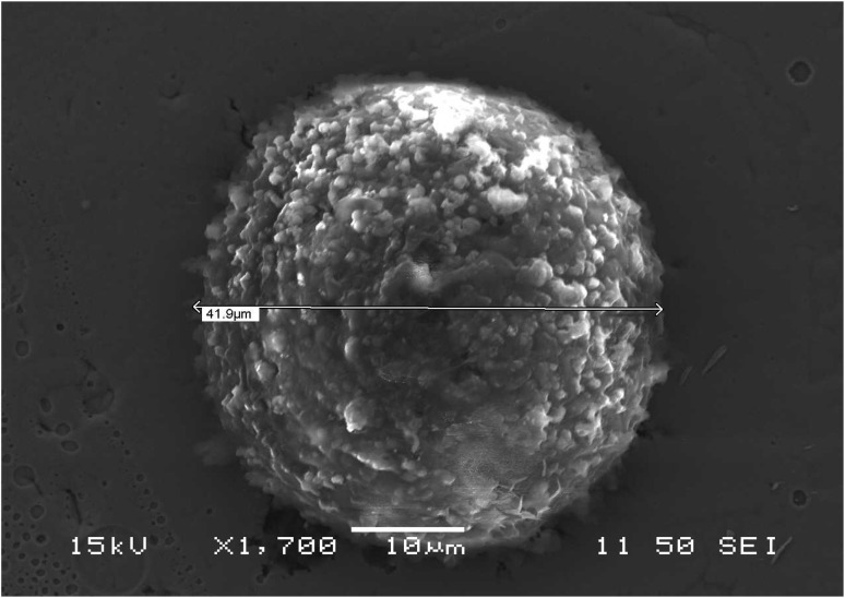
Fig. 6 presents SEM micrograph of a microcapsule embedded in the nickel coating. The surface roughness seen in the images is likely caused by tiny urea-formaldehyde particles sticking together and accumulating at the edge of the capsule. The surface roughness examination conducted using an Olympus LEXT 3D measuring laser microscope CLS4100, with the 3D surface shown in Fig. S11,† reveals that the nickel coating with 20 g L−1 microcapsules exhibits a root mean square roughness (Sq) of 16.638 μm and an arithmetic average roughness (Sa) of 11.451 μm, which are both significantly higher than the pure nickel coating, with Sq at 5.738 μm and Sa at 4.551 μm. The nickel-microcapsule coating also shows a maximum peak height (Sp) of 134.27 μm and maximum valley depth (Sv) of 174.521 μm, compared to Sp of 42.025 μm and Sv of 32.195 μm of nickel coating. The maximum height of surface (Sz) for the microcapsule coating is 308.791 μm, much larger than the nickel coating's Sz of 74.221 μm. Additionally, the surface skewness (Ssk) and Kurtosis (Sku) values for the nickel coating containing microcapsule are 0.971 and 7.865, respectively, indicating a more peaked and asymmetrical surface profile, while the nickel coating has lower Ssk and Sku values of 0.652 and 3.708, respectively. These quantitative differences highlight the increase in surface roughness caused by the incorporation of microcapsules into the nickel coatings.
Fig. 6. SEM micrographs of microcapsules embedded in the nickel coating with a line scale. The roughness of the shell is likely caused by tiny urea-formaldehyde particles sticking together and accumulating at the edge of the capsule.
Fig. S12† presents the EDS analysis of the Ni-PUF microcapsules self-healing coating. Spectra have been obtained for (a) exposed microcapsules, (b) the area surrounded by the nickel coating, and (c) the interface between the microcapsules and nickel. EDS analysis indicates that the nickel weight percentage is 100% in the coating roughly 5 μm adjacent to a microcapsule, as shown in Fig. S12(b).† SEM analysis as shown in Fig. 4–6 reveals that some microcapsules are fully embedded, while others are partially embedded in the self-healing coating. Fig. S13† presents the EDS analysis of the cross-sectional area of the Ni-PUF microcapsule self-healing coating, with spectra for (a) the nickel deposit, (b) the mild steel substrate, and (c) the surface of the microcapsule. The EDS analysis confirms the presence of the main constituents of the capsules, the substrate, and the coating. A heat-quench test was conducted to qualitatively assess the adhesion of nickel and nickel-microcapsule self-healing coatings on mild steel substrates according to ASTM Standard B571-97.56 No flaking or peeling of the deposit was observed for either nickel coating or nickel-microcapsule self-healing coatings, indicating satisfactory adhesion to the substrate.
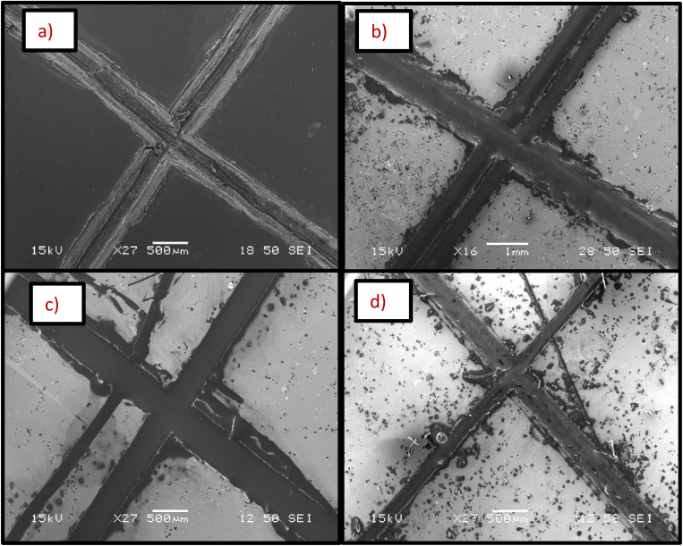
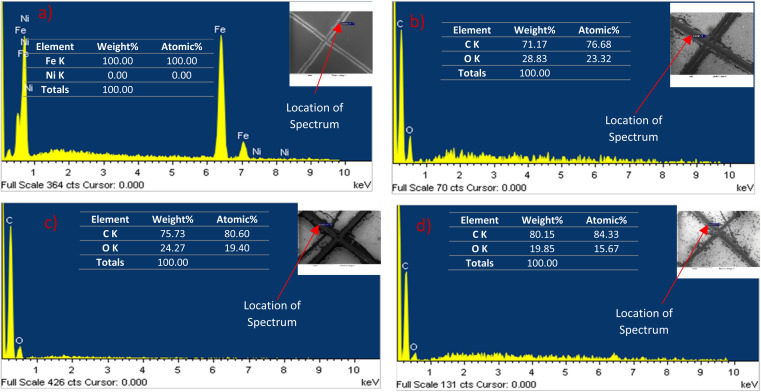
SEM analysis shows that microcapsules, similar to natural healing reservoirs, are uniformly distributed across the substrate, which is essential for the coating to possess effective healing properties. An X-scratch was made on the samples following ASTM D1654-08 (ref. 57) to evaluate the self-healing properties of the synthesized coatings, ensuring the scratch exposed the mild steel substrate. Twenty four hours were given for the linseed oil to flow to the scratched areas to form a protective coating prior to further testing. LO is one of the most common dry oils chosen for self-healing coatings due to its ability to heal and resist corrosion.18,58,59 It predominates in linolenic acid, making it susceptible to oxidation and leading to the formation of a thick, adherent film that serves as a protective layer on the surface.18,58,59 SEM and EDS analyses were conducted on the X-scratched samples, as shown in Fig. 7 and 8. The EDS analysis revealed carbon and oxygen, the main constituents of linseed oil, in the scratched areas, confirming that linseed oil has formed a layer on the scratched regions. While the thickness of the LO layer was not quantified, the EDS results from the scratched regions did not show any appreciable signal from iron in the substrate which indicates the linseed oil coating was likely at least several micrometers thick.
Fig. 7. SEM micrographs of X-scratched samples after 24 hours of making the scratch (a) pristine nickel coating, (b) self-healing coating with 10 g L−1 microcapsules, (c) self-healing coating with 20 g L−1 microcapsules, (d) self-healing coating with 30 g L−1 microcapsules in the bath.
Fig. 8. EDS analysis of the X-scratched samples after 24 hours of making the scratch (a) pristine nickel coating, (b) self-healing coating with 10 g L−1 microcapsules, (c) self-healing coating with 20 g L−1 microcapsules, (d) self-healing coating with 30 g L−1 microcapsules in the bath. EDS analysis reveals that linseed oil has formed a self-healing protective barrier after scratching.
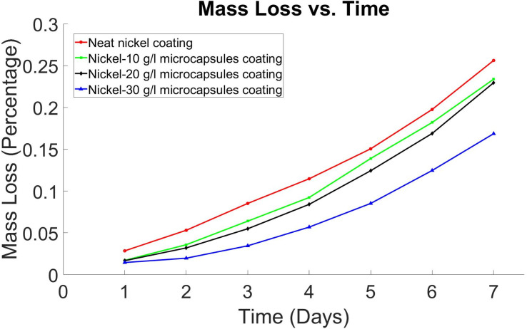
X-scratched samples with 10 g L−1, 20 g L−1, and 30 g L−1 microcapsules were immersed in a 3.5% NaCl solution according to ASTM G31-21 (ref. 44) to assess the corrosion protection properties of the coating. These samples were visually inspected after 6 and 24 hours to evaluate the self-healing coatings' ability to protect the substrate from corrosion. It was observed that after 6 hours, samples without microcapsules and those with 10 g L−1 and 20 g L−1 microcapsules started showing signs of corrosion, indicated by the yellowish color of the NaCl solution, as reported in Table S1 (in ESI†). Samples with 30 g L−1 microcapsules exhibited no corrosion signs after 6 hours. After 24 hours, the sample without microcapsules showed the most corrosion. The mass loss of the samples was calculated after 24 hours, showing that the samples without microcapsules lost 0.0285% of their mass, while those with 10 g L−1, 20 g L−1, and 30 g L−1 microcapsules lost 0.0171%, 0.0167%, and 0.0145%, respectively. This mass loss was recorded every 24 hours up to a total of 7 days, and the results are presented in Fig. 9. After 7 days of immersion, the mass loss in a 3.5% NaCl solution was 0.256% for the sample without microcapsules, 0.233% for the 10 g L−1 microcapsules sample, 0.229% for the 20 g L−1 microcapsules sample, and 0.168% for the 30 g L−1 microcapsules sample. The samples with 30 g L−1 microcapsules provided the best corrosion protection, followed by those with 20 g L−1 and 10 g L−1, with the sample without microcapsules being the least effective.
Fig. 9. Mass loss (percentage) vs. time (days) graph for self-healing nickel coatings.
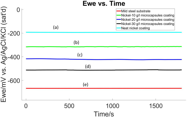
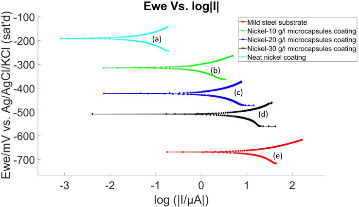
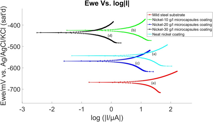
The corrosion performance of self-healing coatings was assessed at room temperature using electrochemical OCP and LP methods, following a 24 hour conditioning period in a 3.5% NaCl electrolyte, before the commencement of these tests. The experimental results, which involved self-healing coating samples without an X-scratch in a 3.5% NaCl electrolyte, are presented in Fig. 10 and 11 and summarized in Table 1. Polarization resistance (Rp) was calculated by determining the slope of the I vs. E plot over a 20 mV range. Tafel plot parameters, including corrosion potential (Ecorr), corrosion current density (Icorr), corrosion rate, and Tafel constants (βa and βc), were determined using EC-Lab software following ASTM G59.60 These results indicated a decrease in the corrosion resistance of the nickel coating when embedded with microcapsules compared to the neat nickel coating. Here, the neat nickel coating exhibited the best performance, while an increase in microcapsule quantity within the coating corresponded to a gradual decrease in electrochemical corrosion resistance. This is attributed to the increase in defects and porosity as the microcapsule quantity increases in the coating, as evidenced by Fig. 4–6 and S9.† However, overall, the self-healing coatings demonstrated improved corrosion protection properties, as evidenced by OCP and LP tests results. Additional studies of the electroplating process may reveal process conditions for electroplating with microcapsules that do not exhibit this detrimental effect in the unscratched condition yet still provide a self-healing benefit.
Fig. 10. OCP diagram of (a) pristine nickel coating, (b) self-healing coating with 10 g L−1 microcapsules, (c) self-healing coating with 20 g L−1 microcapsules, (d) self-healing coating with 30 g L−1 microcapsules, in the bath and (e) mild steel substrate without coating.
Fig. 11. LP diagram of (a) pristine nickel coating, (b) self-healing coating with 10 g L−1 microcapsules, (c) self-healing coating with 20 g L−1 microcapsules, (d) self-healing coating with 30 g L−1 microcapsules, in the bath and (e) mild steel substrate without coating.
Electrochemical data of self-healing coating samples without X scratch.
| Sample | Mild steel substrate | Neat nickel coating | Ni-10 g L−1 MCs coating | Ni-20 g L−1 MCs coating | Ni-30 g L−1 MCs coating |
|---|---|---|---|---|---|
| R p (Ω) | 710 | 286 828 | 15 129 | 6455 | 1736 |
| E corr (mV vs. ref) | −664.846 | −190.083 | −314.802 | −422.943 | −507.741 |
| I corr (μA cm−2) | 8.996 | 0.014 | 0.305 | 0.666 | 2.821 |
| Corrosion rate (mpy) | 4.101 | 5.949 × 10⁻³ | 0.142 | 0.343 | 1.633 |
| β a | 19.8 | 19.7 | 24.4 | 24.6 | 19.8 |
| β c | 48.2 | 21.2 | 23.2 | 18.3 | 28.4 |
In comparing the electrochemical properties of various coatings applied to a mild steel substrate, the following trends are observed:
• Polarization resistance (Rp): the neat nickel coating shows the highest polarization resistance with a Rp value of 286 828 Ω, indicating superior corrosion protection. In contrast, the Ni-30 g L−1 microcapsules (MCs) coating has the lowest resistance at 1736 Ω, suggesting weaker protection. The mild steel substrate itself has the lowest polarization resistance of 710 Ω.
• Corrosion potential (Ecorr): the Ecorr values exhibit a similar trend as Rp. The nickel coating with no microcapsules has a less negative Ecorr (−190.083 mV vs. ref), suggesting a lower tendency to corrode. Conversely, the Ni-30 g L−1 MCs coating has the most negative Ecorr (−507.741 mV vs. ref), indicating a higher propensity for corrosion. The mild steel substrate has the most negative Ecorr value of all (−664.846 mV vs. ref), indicating the highest propensity for corrosion.
• Corrosion current density (Icorr): the neat nickel coating has a significantly lower Icorr (0.014 μA cm−2), pointing to a very low corrosion rate. The Ni-30 g L−1 MCs coating, on the other hand, has a higher Icorr of 2.821 μA cm−2, suggesting a faster corrosion rate. The mild steel substrate exhibits highest Icorr at 8.996 μA cm−2.
• Corrosion rate: consistent with the Icorr results, the neat nickel coating has the lowest corrosion rate at 0.005949 mpy, while the Ni-30 g L−1 MCs coating has the corrosion rate at 1.633 mpy. The mild steel substrate shows the highest corrosion rate at 4.101 mpy.
• Tafel constants (βa and βc): the Tafel constants vary among the coatings, reflecting different electrochemical reaction kinetics. This variation provides further insight into the corrosion mechanisms of the different coatings. For example, a coating with a higher βa value would indicate a faster anodic reaction rate, suggesting that the coating is more susceptible to oxidative corrosion processes. Conversely, a higher βc value would indicate a faster cathodic reaction rate, implying a greater tendency for reduction reactions, such as the reduction of oxygen in the corrosion process. However, it is important to note that precise knowledge of the Tafel constants is often not critical. In the typical range of values seen in electrochemical systems, the impact on corrosion rate from significant variations in Tafel constants is minor compared to equivalent changes in Rp.61
Summarizing the electrochemical testing results, the neat nickel coating is the most effective in protecting the mild steel substrate against corrosion, as indicated by its high Rp, the least negative Ecorr, and the lowest Icorr and corrosion rate. The Ni-30 g L−1 MCs coating offers the least protection, with the lowest Rp and highest values in Icorr and corrosion rate. The Ni-10 g L−1 MCs and Ni-20 g L−1 MCs coatings provide moderate levels of protection, falling between these two extremes. However, overall, the self-healing coatings demonstrated improved corrosion protection properties than the mild steel substrate.
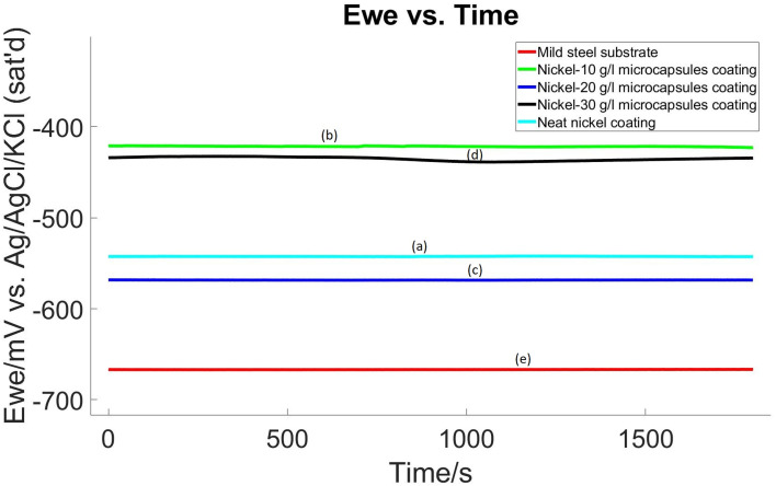
The corrosion performance of the coatings after making an X-scratch was examined using OCP and LP methods following 24 hour conditioning period in the electrolyte at room temperature and the same procedure and electrolyte as was used in non-scratched samples. Results are presented in Fig. 12 and 13, with a summary in Table 2. These results revealed an interesting trend: the corrosion resistance of nickel coatings embedded with microcapsules was enhanced post X-scratch, in contrast to the neat nickel coating.
Fig. 12. OCP diagram of X-scratched samples (a) pristine nickel coating, (b) self-healing coating with 10 g L−1 microcapsules, (c) self-healing coating with 20 g L−1 microcapsules, (d) self-healing coating with 30 g L−1 microcapsules, in the bath and (e) mild steel substrate without coating.
Fig. 13. LP diagram of X-scratched samples (a) pristine nickel coating, (b) self-healing coating with 10 g L−1 microcapsules, (c) self-healing coating with 20 g L−1 microcapsules, (d) self-healing coating with 30 g L−1 microcapsules, in the bath and (e) mild steel substrate without coating.
Electrochemical data of coating of X-scratched samples.
| Sample | Mild steel substrate | Neat nickel coating | Ni-10 g L−1 MCs coating | Ni-20 g L−1 MCs coating | Ni-30 g L−1 MCs coating |
|---|---|---|---|---|---|
| R p (Ω) | 710 | 951 | 3234 | 3401 | 37 270 |
| E corr (mV vs. ref) | −664.846 | −542.503 | −424.704 | −568.070 | −435.250 |
| I corr (μA cm−2) | 8.996 | 7.006 | 1.708 | 0.771 | 0.148 |
| Corrosion rate (mpy) | 4.101 | 2.975 | 0.796 | 0.398 | 0.062 |
| β a | 19.8 | 26.0 | 29.5 | 10.5 | 29.2 |
| β c | 48.2 | 36.8 | 27.3 | 14.3 | 27.1 |
The electrochemical data extracted from these tests, as detailed in Table 2, showed that the neat nickel coating, while initially offering the best corrosion resistance in non-scratched samples, exhibited the lowest resistance in the X-scratched samples. As the concentration of microcapsules in the nickel coating increased, there was a notable improvement in corrosion resistance post-scratch. This trend suggests that the self-healing properties of the coatings are effectively activated upon scratching.
In examining the properties of the various coatings on a mild steel substrate, the following observations were made:
For X-scratched samples, the Ni-30 g L−1 MCs coating displayed the highest polarization resistance with an Rp value of 37 270 Ω, indicating exceptional corrosion protection post-scratch. This is a stark contrast to the neat nickel coating, which showed a much lower Rp value of 951 Ω. The mild steel substrate itself exhibited the lowest polarization resistance at 710 Ω. The Ecorr values also mirrored this trend. The Ni-30 g L−1 MCs coating had a less negative Ecorr (−435.250 mV vs. ref) compared to the neat nickel coating (−542.503 mV vs. ref), suggesting a reduced tendency to corrode post-scratch. The mild steel substrate maintained the most negative Ecorr value (−664.846 mV vs. ref), indicating the highest inherent corrosion propensity. In the context of Icorr, the Ni-30 g L−1 MCs coating exhibited a significantly lower value (0.148 μA cm−2), pointing to a remarkably reduced corrosion rate post-scratch. This was a substantial improvement over the neat nickel coating, which had a higher Icorr of 7.006 μA cm−2. The mild steel substrate recorded the highest Icorr at 8.996 μA cm−2. In alignment with the Icorr findings, the Ni-30 g L−1 MCs coating demonstrated the lowest corrosion rate at 0.062 mpy post-scratch, significantly outperforming the neat nickel coating, which had a higher corrosion rate of 2.975 mpy. The mild steel substrate showed the highest corrosion rate at 4.101 mpy. The Tafel constants (βa and βc) for these coatings varied, indicating different electrochemical reaction kinetics.
In summary, the Ni-30 g L−1 MCs coating was the most effective in enhancing the corrosion resistance of the mild steel substrate post-scratch, as evidenced by its high Rp, improved Ecorr, lowest Icorr, and significantly reduced corrosion rate. This performance can be attributed to the effective activation of self-healing mechanisms, likely due to the protective barrier formed by the linseed oil released from the microcapsules upon scratching. The Ni-10 g L−1 MCs and Ni-20 g L−1 MCs coatings also showed improved performance post-scratch, but to a lesser extent than the Ni-30 g L−1 MCs coating. Before the X-scratch, OCP values vary significantly, but after the scratch, OCP values are similar across different self-healing coating samples. This may be because, after the X-scratch, OCP is dictated by the extent of the scratch while before the scratch, OCP is dominated by microcapsule-induced defects.
It is crucial for future research to focus on several key areas. Firstly, it is important to synthesize nanocapsules using similar methods to those used for microcapsules. Then, these nanocapsules should be electrodeposited with nickel or other corrosion-resistant metals to assess their impact on self-healing coatings. It is also important to synthesize metallic coatings with multicycle healing capabilities, allowing for repeated self-repair. To precisely quantify the healing liquid in scratched areas, analytical and computational modeling should be utilized. This will help determine optimum conditions such as capsule weight percentage, healing time, crack size and shape, and environmental factors that will maximize healing effectiveness. It is also crucial to explore various healing agents, such as tung oil, castor oil, and octyldimethyl-silly-linoleate, to compare their healing efficiency. Additionally, it is essential to investigate the interaction between capsule shell materials (both organic and inorganic) and the matrix, especially their interfacial strength. In-depth research is necessary to fully comprehend the mechanisms underlying the healing and anti-corrosion properties, as well as the effects of these capsules on the mechanical characteristics of self-healing metallic coatings.
4. Conclusions
A bioinspired self-healing nickel coating incorporating poly(urea-formaldehyde) (PUF) microcapsules filled with linseed oil was successfully synthesized. Characterization of the synthesized microcapsules and the nickel coating incorporating these microcapsules, using techniques including optical microscopy, SEM, and EDS, confirmed the successful incorporation of the microcapsules into the nickel coating. The self-healing properties of the coating were demonstrated through SEM and EDS analyses after scratching, which showed the presence of linseed oil in the scratched area and confirmed the self-healing functionality of the coatings. The nickel coatings containing microcapsules exhibited enhanced corrosion resistance, compared to neat nickel coatings with similar X-scratches, during immersion testing in 3.5% NaCl solution. The coating containing 30 g L−1 of microcapsules exhibited the lowest mass loss due to corrosion. The OCP and LP tests conducted on self-healing coating samples in a 3.5% NaCl solution showed that for samples without an X-scratch, embedding microcapsules into the nickel coating led to a decrease in corrosion resistance compared to the neat nickel coating. However, after scratching, the corrosion resistance of the nickel-microcapsule coatings was much higher than that of neat nickel coating with similar scratches. Increasing the amount of microcapsules in the coating resulted in higher corrosion resistance after scratching. This enhanced corrosion resistance is attributed to the auto-oxidation and polymerization of linseed oil released from the microcapsules after scratching, which flows into the crack and polymerizes to form a protective barrier, improving corrosion resistance.
Data availability
The data that support the findings of this study are available from the corresponding author upon reasonable request.
Author contributions
Conceptualization, M. B., M. N., B. C. and P. R.; methodology, M. B., M. N., B. C. and P. R.; software, M. B., and B. C.; validation, M. B., M. N., B. C. and P. R.; formal analysis, M. B., M. N., B. C. and P. R; investigation, M. B., M. N., B. C. and P. R.; resources, M. B., M. N., B. C. and P. R.; data curation, M. B.; writing – original draft preparation, M. B.; writing – review and editing, M. B., M. N., B. C. and P. R.; visualization, M. B., M. N., B. C. and P. R.; supervision, M. N., B. C. and P. R.; project administration, M. B., M. N., B. C. and P. R.; funding acquisition, P. R. All authors have read and approved the final manuscript for publication.
Conflicts of interest
There is no conflict of interest.
Supplementary Material
Acknowledgments
Electron microscopy, DSC, and LPDSA were conducted at the Advanced Analysis Facility of University of Wisconsin-Milwaukee.
Electronic supplementary information (ESI) available. See DOI: https://doi.org/10.1039/d4ra07469f
References
- Marcus P., Corrosion Mechanisms in Theory and Practice, 3rd edn, CRC Press, 2011 [Google Scholar]
- Silva A. C. M. Moghadam A. D. Singh P. Rohatgi P. K. J. Coat. Technol. Res. 2017:1–29. [Google Scholar]
- Bellah M., Nosonovsky M. and Rohatgi P., in Metal-Matrix Composites, ed. T. S. Srivatsan, P. K. Rohatgi and S. Hunyadi Murph, Springer International Publishing, Cham, 2022, pp. 297–310 [Google Scholar]
- Rohatgi P. Bellah M. Srivastava V. J. Mater. Res. 2024;39:1597–1621. [Google Scholar]
- The High Cost of Corrosion, https://www.polygongroup.com/en-US/blog/the-high-cost-of-corrosion/, accessed 31 December 2023
- Bender R. Féron D. Mills D. Ritter S. Bäßler R. Bettge D. De Graeve I. Dugstad A. Grassini S. Hack T. Halama M. Han E.-H. Harder T. Hinds G. Kittel J. Krieg R. Leygraf C. Martinelli L. Mol A. Neff D. Nilsson J.-O. Odnevall I. Paterson S. Paul S. Prošek T. Raupach M. Revilla R. I. Ropital F. Schweigart H. Szala E. Terryn H. Tidblad J. Virtanen S. Volovitch P. Watkinson D. Wilms M. Winning G. Zheludkevich M. Mater. Corros. 2022;73:1730–1751. [Google Scholar]
- Yabuki A. and Fathona I. W., in Advances in Smart Coatings and Thin Films for Future Industrial and Biomedical Engineering Applications, ed. A. S. H. Makhlouf and N. Y. Abu-Thabit, Elsevier, 2020, pp. 99–133 [Google Scholar]
- Hashmi A. W., Singh J. and Ahmad S., in Discovery, Disruption, and Future Implications of Nanomaterials, IGI Global, 2024, pp. 597–624 [Google Scholar]
- Chilukuri A., Murugesan S. and Monteiro O., US Pat., 20170051156A1, 2017
- Sadabadi H. Allahkaram S. R. Kordijazi A. Rohatgi P. K. Prot. Met. Phys. Chem. Surf. 2022;58:287–307. [Google Scholar]
- Sun C. Yarmohammadi A. Isfahani R. B. Nejad M. G. Toghraie D. Fard E. K. Saber-Samandari S. Khandan A. J. Mol. Liq. 2021;325:115182. [Google Scholar]
- Song Y. K. Lee T. H. Lee K. C. Choi M. H. Kim J. C. Lee S.-H. Noh S. M. Park Y. I. Appl. Surf. Sci. 2020;511:145556. [Google Scholar]
- Cui X. Yan Y. Huang J. Qiu X. Zhang P. Chen Y. Hu Z. Liang X. Appl. Surf. Sci. 2022;579:152186. [Google Scholar]
- Wang L. Wang X. Liu T. Sun F. Li S. Geng Y. Yao B. Xu J. Fu J. npj Mater. Degrad. 2023;7:1–15. [Google Scholar]
- Nosonovsky M. Amano R. Lucci J. M. Rohatgi P. K. Phys. Chem. Chem. Phys. 2009;11:9530–9536. doi: 10.1039/b912433k. [DOI] [PubMed] [Google Scholar]
- Nosonovsky M. Bhushan B. Philos. Trans. R. Soc., A. 2009;367:1607–1627. doi: 10.1098/rsta.2009.0009. [DOI] [PubMed] [Google Scholar]
- Nosonovsky M. Bhushan B. Appl. Surf. Sci. 2010;256:3982–3987. [Google Scholar]
- Sadabadi H. Allahkaram S. R. Kordijazi A. Rohatgi P. K. J. Mater. Eng. Perform. 2023;33:925–936. [Google Scholar]
- Li Z. Guo Z. Nanoscale. 2023;15:1493–1512. doi: 10.1039/d2nr05952e. [DOI] [PubMed] [Google Scholar]
- Malekkhouyan R. Neisiany R. E. Khorasani S. N. Das O. Berto F. Ramakrishna S. J. Appl. Polym. Sci. 2021;138:49964. [Google Scholar]
- Cremaldi J. C. Bhushan B. Beilstein J. Nanotechnol. 2018;9:907–935. doi: 10.3762/bjnano.9.85. [DOI] [PMC free article] [PubMed] [Google Scholar]
- Diesendruck C. E. Sottos N. R. Moore J. S. White S. R. Angew. Chem., Int. Ed. Engl. 2015;54:10428–10447. doi: 10.1002/anie.201500484. [DOI] [PubMed] [Google Scholar]
- Bauer G., Nellesen A. and Speck T., Presented in Design and Nature, Pisa, Italy, 2010 [Google Scholar]
- Nellesen A. von Tapavicza M. Bertling J. Schmidt A. M. Bauer G. Speck T. Int. Polym. Sci. Technol. 2011;38:1–4. [Google Scholar]
- Bauer G. Speck T. Ann. Bot. 2012;109:807–811. doi: 10.1093/aob/mcr307. [DOI] [PMC free article] [PubMed] [Google Scholar]
- Merchán-Gaitán J. B. Mendes J. H. L. Nunes L. E. C. Buss D. S. Rodrigues S. P. Fernandes P. M. B. Viruses. 2024;16:47. doi: 10.3390/v16010047. [DOI] [PMC free article] [PubMed] [Google Scholar]
- White S. R. Sottos N. R. Geubelle P. H. Moore J. S. Kessler M. R. Sriram S. R. Brown E. N. Viswanathan S. Nature. 2001;409:794–797. doi: 10.1038/35057232. [DOI] [PubMed] [Google Scholar]
- Reda M. A. Chidiac S. E. Constr. Build. Mater. 2024;436:136984. [Google Scholar]
- Li P. Lu Z. Ma K. Zou G. Chang L. Guo W. Tian K. Li X. Wang H. Prog. Org. Coat. 2022;163:106636. [Google Scholar]
- Li P. Guo W. Ma K. Chang L. Tian K. Li X. Wang H. Appl. Surf. Sci. 2023;616:156537. [Google Scholar]
- Sun D. Yan Z. Mingzhang L. Ziming W. Suping C. Jinglei Y. Appl. Surf. Sci. 2021;546:149114. [Google Scholar]
- Ye K. Bi Z. Cui G. Zhang B. Li Z. Corrosion. 2020;76:279–298. [Google Scholar]
- An S. Lee M. W. Yarin A. L. Yoon S. S. Chem. Eng. J. 2018;344:206–220. [Google Scholar]
- Kharaji S., in Introduction to Corrosion – Basics and Advances, IntechOpen, 2023 [Google Scholar]
- Habib S. Khan A. Nawaz M. Sliem M. H. R. Shakoor R. A. Kahraman R. Abdullah A. M. Zekri A. Polymers. 2019;11:1519. doi: 10.3390/polym11091519. [DOI] [PMC free article] [PubMed] [Google Scholar]
- Khun N. W. Zhang H. Yang J. L. Liu E. Wear. 2012;296:575–582. [Google Scholar]
- Xu X. Liu H. Li W. Zhu L. Mater. Lett. 2011;65:698–701. [Google Scholar]
- Liqun Z. Wei Z. Feng L. He Y. J. Mater. Sci. 2004;39:495–499. [Google Scholar]
- Zhu L. Feng L. He Y. Plat. Surf. Finish. 2005;92:49–52. [Google Scholar]
- Aruna S. T. Arunima S. Latha S. William Grips V. K. Mater. Manuf. Processes. 2016;31:107–111. [Google Scholar]
- Alexandridou S. Kiparissides C. Fransaer J. Celis J. P. Surf. Coat. Technol. 1995;71:267–276. [Google Scholar]
- Churruca M. J., Castro P. A. and Williams F. J., US Pat., US8771494B2, 2014
- Sadabadi H. Allahkaram S. R. Ghader O. Rohatgi P. K. J. Met., Mater. Miner. 2022;32:143–149. [Google Scholar]
- ASTM G31-21, Standard Guide for Laboratory Immersion Corrosion Testing of Metals, ASTM International, 2021 [Google Scholar]
- Brown E. N. Kessler M. R. Sottos N. R. White S. R. J. Microencapsulation. 2003;20(6):719–730. doi: 10.1080/0265204031000154160. [DOI] [PubMed] [Google Scholar]
- Blaiszik B. J. Sottos N. R. White S. R. Compos. Sci. Technol. 2008;68:978–986. [Google Scholar]
- Rule J. D. Sottos N. R. White S. R. Polymer. 2007;48:3520–3529. [Google Scholar]
- Zheludkevich M. L. Tedim J. Ferreira M. G. S. Electrochim. Acta. 2012;82:314–323. [Google Scholar]
- Sauvant-Moynot V. Gonzalez S. Kittel J. Prog. Org. Coat. 2008;63:307–315. [Google Scholar]
- Bakry A. M. Abbas S. Ali B. Majeed H. Abouelwafa M. Y. Mousa A. Liang L. Compr. Rev. Food Sci. Food Saf. 2016;15:143–182. doi: 10.1111/1541-4337.12179. [DOI] [PubMed] [Google Scholar]
- Silva A. C. M. Renzetti R. A. Andrada A. de S. Singh P. Rohatgi P. K. da Silva M. C. J. Coat. Technol. Res. 2020;17:1351–1361. [Google Scholar]
- Xu X. Zhu L. Li W. Liu H. Trans. Nonferrous Met. Soc. China. 2011;21:2210–2215. [Google Scholar]
- Besra L. Liu M. Prog. Mater. Sci. 2007;52:1–61. [Google Scholar]
- Nesterova T. Dam-Johansen K. Pedersen L. T. Kiil S. Prog. Org. Coat. 2012;75:309–318. [Google Scholar]
- Wang W. Xu L. Li X. Lin Z. Yang Y. An E. J. Mater. Chem. A. 2014;2:1914–1921. [Google Scholar]
- ASTM B571-97, Standard Practice for Qualitative Adhesion Testing of Metallic Coatings, ASTM International, 2013 [Google Scholar]
- ASTM D1654-08, Standard Test Method for Evaluation of Painted or Coated Specimens Subjected to Corrosive Environments, ASTM International, 2008 [Google Scholar]
- Behzadnasab M. Mirabedini S. M. Esfandeh M. Farnood R. R. Prog. Org. Coat. 2017;105:212–224. [Google Scholar]
- Wang H. Zhou Q. Prog. Org. Coat. 2018;118:108–115. [Google Scholar]
- ASTM G59-97, Standard Test Method for Conducting Potentiodynamic Polarization Resistance Measurements, ASTM International, 2020 [Google Scholar]
- Kelly R. G., Scully J. R., Shoesmith D. and Buchheit R. G., Electrochemical Techniques in Corrosion Science and Engineering, CRC Press, 2002 [Google Scholar]
Associated Data
This section collects any data citations, data availability statements, or supplementary materials included in this article.
Supplementary Materials
Data Availability Statement
The data that support the findings of this study are available from the corresponding author upon reasonable request.


