Abstract
Frictional vibration often occurs during sliding, commonly referred to as the stick-slip phenomenon. It is more likely to occur in the range of the Stribeck curve, where friction and velocity have negative gradient characteristics. In this study, ultrasonic vibration is applied to the metal/metal sliding friction pair which reduce both static and kinetic friction forces. The inhibition mechanism of ultrasonic vibration on the stick-slip phenomenon is investigated for a sliding pair moving at low velocities (0.05–1.0 mm/s) under the condition of dry friction and oil lubrication. Under the condition of dry friction, ultrasonic vibration reduces the slider’s friction force by up to 89%, and the displacement fluctuation by up to 61%, effectively inhibiting the stick-slip phenomenon. Under the condition of oil lubrication, the friction force fluctuates when driving at a constant velocity, and the displacement fluctuation also fluctuates with the change of driving velocities. After ultrasonic vibration is applied, the friction reduction of the slider changes greatly with the driving velocity, so that the inhibition effect of ultrasonic vibration on stick-slip phenomenon under oil lubrication condition is unstable.
Keywords: Ultrasonic vibration, Stick-slip phenomenon, Friction reduction, Difference between static and kinetic friction force, Displacement fluctuation
Subject terms: Mechanical engineering, Fluid dynamics
Introduction
In a broad sense, stick-slip phenomenon refers to the non-uniform motion of a component driven at a uniform velocity. In the feed movement and adjustment movement of precision machine tool and heavy machine tool, at low velocity, there will be a stop-and-jump form of movement, that is, the so-called stick-slip motion. Usually the so-called stick-slip phenomenon mainly refers to this form of movement1,2.
In order to improve the machining accuracy of the machine tool, the use of higher resolution system can reduce the control error of the CNC system, the use of gear gap compensation, lead screw error compensation, tool compensation, and thermal deformation error compensation can reduce the error of the transmission system, but the error caused by the stick-slip phenomenon of the guide rail can not be eliminated by the control system. Stick-slip phenomenon will lead to low-velocity instability of the ultra-precision machine tool, reduce the positioning accuracy and sensitivity of the machine tool, and lead to a reduction in processing accuracy and part surface quality. The stick-slip phenomenon also accelerates the wear of the guide rail and reduces the dimensional accuracy of the rail. Sliding guide rails have advantages in vibration absorption, damping, contact stiffness, bearing capacity and economy. Because of the stick-slip motion at low velocity, it is difficult to ensure the smooth motion and positioning accuracy, which limits its application in high-precision occasions. Therefore, it is very important to solve the stick-slip motion problem of sliding guide rails.
The most widely accepted stick-slip theory is that of B. Э. Πyш, a Soviet scientist, who proposed that stick-slip motion occurs because of the difference between static and kinetic friction force in the early 1960s1. The existing research results have pointed out some qualitative directions to solve the stick-slip motion problem, reducing the difference between static and kinetic friction force, improving the stiffness and the damping ratio of the system. Due to structural limitations and economic considerations, usually the main measure to improve the precision of micro-displacement and inhibit the stick-slip motion is to reduce the difference between static and kinetic friction force1,3.
As early as the 1860s, it has been proved that vibration can greatly reduce the friction coefficient of metal sliding friction pairs4,5. More in-depth and extensive research on the friction reducing effect of ultrasonic vibration began in the 1990s. The research results of K. Adachi show that the friction force after applying ultrasonic vibration is less than one-tenth of the original friction force, and the friction force is a function of load, amplitude of vibration and relative sliding velocity6. According to Littmann et al., when the direction of vibration is parallel to the sliding direction of slider, its friction reducing effect is related to the ratio of the moving velocity to the vibration velocity, and the smaller the ratio, the better the friction reducing effect7. Kumar proved that ultrasonic vibration parallel or perpendicular to the sliding direction can greatly reduce the friction force, and its reduction value is greater than 80% of the original friction force8. Gutowski verified that the longitudinal vibration applied on the sliding direction of the friction pair can reduce the friction force and thus reduce the driving force in the sliding direction9. S. Dong proposed an elastic-plastic cube model applied to a variety of vibration friction reducing phenomena, and studied the friction reducing effect between aluminum alloy and stainless steel under the normal pressure between 40 N and 240 N, and the maximum friction can be reduced to 40% of the original10. Meanwhile, S. Dong also pointed out that ultrasonic vibrations reduce the effective friction force up to 62% along with a wear reduction of up to 49% and stick-slip phenomenon between two sliding surfaces at considered sliding velocities11. T. Oiwa et al. applied ultrasonic vibration to improve the linear motion positioning accuracy of ball bearings, reducing the maximum displacement error by about 40% and the average error by 26%12,13. T. Engel et al. designed a linear drive bearings with integrated ultrasonic vibration to control friction force and reduce stick-slip movement by ultrasonic vibration14. Cheng et al. applied ultrasonic friction reduction effect to stick-slip actuator to achieve high velocity, large mass of load and smooth displacement15.
The friction reducing effect of ultrasonic vibration is significant, which is mainly used in machining, driving and mechanical friction reduction. However, there are few studies on the application of this effect to reduce stick-slip phenomenon and improve the displacement accuracy, and these studies are qualitative or indirect methods such as critical stick-slip velocity to show that ultrasonic vibration can reduce stick-slip motion. In this paper, two parameters namely velocity fluctuation and displacement fluctuation which can directly describe the stick-slip motion, are used to quantitatively analyze the stick-slip motion reduction on metal/metal sliding friction pairs under the conditions of dry friction and oil lubrication which is related to friction reducing effect of ultrasonic vibration. We also analyzed the relationship between displacement fluctuation and velocity fluctuation and the reduction of the difference between static and kinetic friction caused by ultrasonic vibration. It can provide guidance for the subsequent development of high-precision sliding guide rails.
Methods and experiments
Experimental set-up
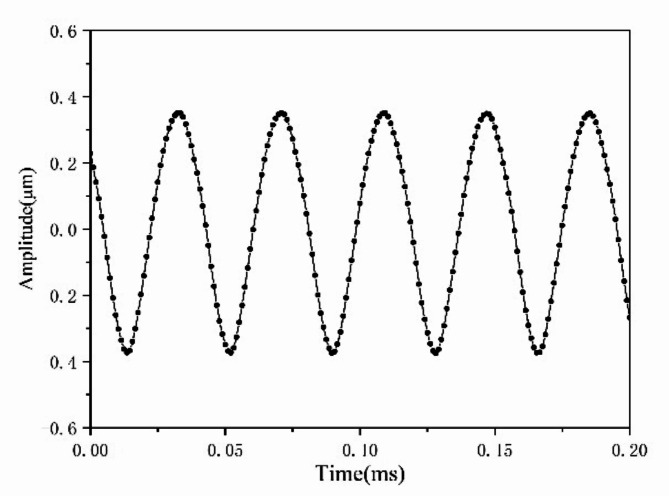
The experimental platform for testing friction and motion characteristics of sliding friction pair with ultrasonic vibration was built to simulate the stick-slip motion of sliding guide rail at low velocity, as shown in Fig. 1. The upper slide block of the sliding friction pair is a moving slider, the weight of the moving slider is about 1.1Kg, simulating the moving guide rail, and the lower sliding block is a fixed slider, simulating the fixed guide rail, the material of the slider is 40Cr steel (ASTM: 5140) with a hardness of 525 ± 15 HV and surface roughness of Ra 0.4 ± 0.02 after laser quenching. The voice coil linear motor of type VCAR0436-250 drives the moving slider to simulate the linear motion of the sliding guide rail. The ultrasonic vibration was applied to the fixed slider, and the direction of vibration is the same as that of the slider. The ultrasonic vibration parameters were measured by fiber laser vibrometer of type LV-FS01-H, as shown in Fig. 2. The vibration frequency was 26k Hz, the amplitude was 0.35 μm. The force sensor of type ZLBS-50 N with a resolution of 0.025 N and a sampling frequency of 10 Hz was used to test the change of force and the maximum static friction force during the driving process of the moving slider (The friction force is the average of the three measurements). The HC-LPT030 laser displacement sensor with an accuracy of 0.3 μm and a sampling frequency of 1000 Hz was used to measure the displacement of the moving slider.
Fig. 1.
Schematic diagram of the friction and motion characteristics test platform.
Fig. 2.
The curve of ultrasonic vibration.
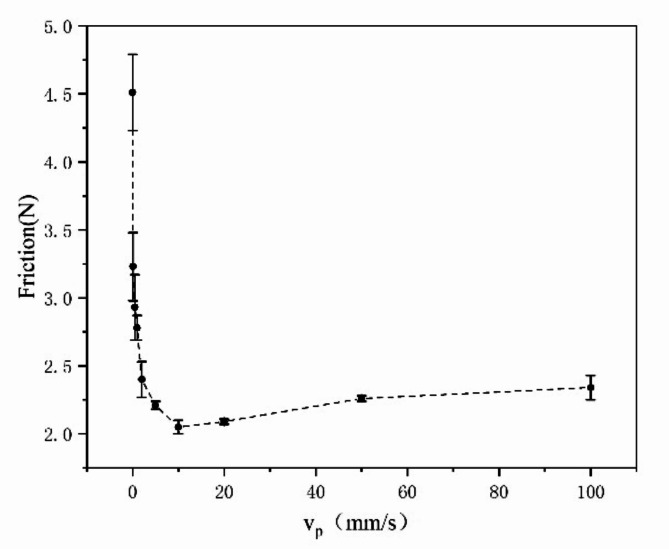
Figure 3 shows the changes of friction force at different sliding velocities under dry friction conditions. In dry friction, the changes of kinetic friction force with velocity conform to the Stribeck curve, and the velocity corresponding to the minimum value of kinetic friction force is vs = 10 mm/s. When the velocity is lower than vs, the friction force decreases with the increase of velocity. To test the stick-slip phenomenon of slider at low velocity and the effect of ultrasonic vibration on the stick-slip inhibition, the experiment drive velocity is selected in the low velocity area on the left side of vs, which are 0.05 mm/s, 0.1 mm/s, 0.2 mm/s, 0.5 mm/s and 1.0 mm/s. Displacement fluctuation (ΔS, the maximum difference between the actual and theoretical displacement of the moving slider at the same time interval) and velocity fluctuation (Δv, the difference between the maximum and minimum velocity of the moving slider at the same time interval) are used to quantify the stick-slip motion of the slider16. The displacement fluctuation can be obtained by the displacement curve measured by the laser displacement sensor, while the velocity fluctuation can be obtained by the displacement data calculated by the velocity curve of equation:
 |
1 |
where vi is the velocity value of the ith point, Si is the displacement value of the ith point, Δt is the displacement sampling interval time, and Δt in this experiment is 0.001 s.
Fig. 3.
The variation of friction force at different velocities under dry friction condition.
Mechanism of ultrasonic vibration friction reduction
According to the existing studies in the field of ultrasonic vibration friction reduction, vibration in different directions will reduce the friction force between friction pairs, regardless of whether the vibration direction is parallel or perpendicular to the relative motion direction6,17. The direction of ultrasonic vibration applied in this paper is parallel to the sliding direction of slider and the mechanism of ultrasonic vibration friction reduction is to calculate the average friction force of high-frequency reciprocating motion17.
As shown in Fig. 4, in one ultrasonic vibration cycle, vb(t) is the vibration velocity of the fixed slider caused by ultrasonic vibration, which is a sine curve, and vp(t) is the driving velocity of the moving slider. In this experiment, the ultrasonic vibration frequency is 26k Hz and the amplitude is about 0.35 μm, so the calculated maximum vibration velocity vb is about 57 mm/s, which is greater than the moving velocity vp of the moving slider. The points at which vb(t) intersects with vp(t) and -vp(t) are projected onto the horizontal time axis are A, B, C, and D. During the interval AB, vb(t) > vp(t) and then the direction of relative motion of the moving slider and the fixed slider is opposite, so the direction of friction is also opposite. The resultant average frictional force over the whole cycle is reduced.
Fig. 4.
The mechanism of ultrasonic vibration friction reduction when the vibration direction is parallel to the sliding direction.
Results and discussion
Friction reduction Effect under Dry Friction Condition
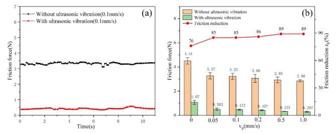
Figure 5 shows the friction reduction under dry friction condition at different low velocity movements applied with ultrasonic vibration. Figure 5a shows the friction force curve when vp = 0.1 mm/s, and the friction force is reduced by about 85%, and the friction curve is smoother applied with ultrasonic vibration. In Fig. 5b, vp = 0 mm/s indicates the maximum static friction force of the moving slider, and the ultrasonic vibration reduces the maximum static friction force by about 76%. As can be seen from Fig. 5, ultrasonic vibration can significantly reduce the kinetic friction force by nearly 90%. The friction reduction εF can be expressed as:
 |
2 |
Fig. 5.
The influence of friction force applied with or without ultrasonic vibration under dry friction conditions: (a) vp = 0.1 mm/s, (b) at different driving velocities.
where F0 and Ff are the static friction force and kinetic friction force when ultrasonic vibration is not applied, and Fv0 and Fvf are the static friction force and kinetic friction force when ultrasonic vibration is applied.
The difference between static and kinetic friction force after applied with or without ultrasonic vibration is shown in Fig. 6, where ΔF is the one without ultrasonic vibration which can be calculated by  , and ΔFv is the one with ultrasonic vibration which can be calculated by
  . In the low-velocityarea of the experimental test, using ultrasonic vibration can effectively reduce the difference between static and kinetic friction force, and its reduction εΔF increases with the increase of velocity, from 53 to 56%. εΔF can be expressed as:
 |
3 |
Fig. 6.
The influence of the difference between static and kinetic friction force after applying ultrasonic vibration under dry friction conditions.
In this experiment, the ratio of sliding velocity to the maximum ultrasonic vibration velocity is tend to 0 due to the slider’s low sliding velocity. According to the ultrasonic vibration friction reduction models7,10,18,19, the frictional friction reduction rate will be close to 100%, which is inconsistent with the experimental data which is close to 90%. Similar situations are also mentioned in the references 18 and19. This paper mainly focuses on the influence of ultrasonic vibration on stick-slip motion, and and the theoretical model of ultrasonic vibration friction reduction will be further studied and analyzed in the later stage. In the low sliding velocity range of the slider, the deviation between the experimental data and the theoretical data may be due to the pre-sliding displacement.
Figure 7 shows the stick-slip phenomenon of the moving slider during the time interval of 0.5 s at different driving velocities under dry friction condition with and without ultrasonic vibration, including the displacement curves, displacement fluctuation curves and velocity fluctuation curves. In the figure, ΔS is the displacement fluctuation without ultrasonic vibration, ΔSv is the displacement fluctuation with ultrasonic vibration, Δv is the velocity fluctuation without ultrasonic vibration, and Δvv is the velocity fluctuation with ultrasonic vibration. In Fig. 7a, the driving velocity of the moving slider is vp = 0.05 mm/s, and the displacement fluctuation reaches 4 μm when there is no ultrasonic vibration, which is about 16% of the theoretical displacement 25 μm, and the velocity fluctuation is 0.34 mm/s, which is about 7 times of the velocity value. Serious stick-slip phenomenon occurs during low-velocity micro-displacement movement. When ultrasonic vibration is applied, the displacement fluctuation is reduced to 1.7 μm, down 58%, and the velocity fluctuation is 0.22 mm/s, down 35%. Ultrasonic vibration can significantly reduce the stick-slip phenomenon at the velocity of 0.05 mm/s. As can be seen from displacement fluctuation curves and velocity fluctuation curves in Fig. 7, the displacement fluctuation and velocity fluctuation can be effectively reduced by applying ultrasonic vibration.
Fig. 7.
Stick-slip curves of the moving slider with or without ultrasonic vibration under dry friction condition.
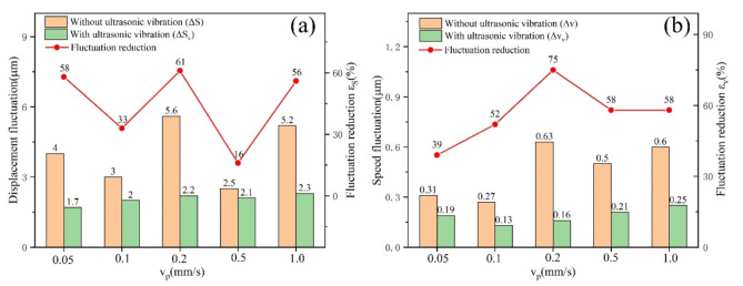
Figure 8 shows the influence of ultrasonic vibration on the displacement fluctuation and velocity fluctuation of the moving slider under different driving velocities. The displacement fluctuations and velocity fluctuations are not linearly correlated with the moving velocities. When the driving velocity is vp = 0.2 mm/s, there is the maximum displacement fluctuation (ΔS = 5.6 μm) and velocity fluctuation (Δv = 0.65 mm/s). At the same time, it also has the largest displacement fluctuation reduction εS = 61% and the largest velocity fluctuation reduction εv = 72% after applying ultrasonic vibration. After applying ultrasonic vibration, the displacement fluctuation is the smallest when vp = 0.05 mm/s (ΔSv = 1.7 μm), and the velocity fluctuation is the smallest when vp = 0.1 mm/s (Δvv = 0.16 mm/s). When there is no ultrasonic vibration, the displacement fluctuation of the moving slider at different moving velocities ranges from 2.5 μm to 5.6 μm. After applying ultrasonic vibration, the displacement fluctuation tends to be smaller and more stable, ranging from 1.7 μm to 2.3 μm. Displacement fluctuation reduction εS and velocity fluctuation reduction εv can be expressed as:
 |
4 |
 |
5 |
Fig. 8.
Stick-slip phenomenon at different driving velocities with or without ultrasonic vibration under dry friction condition: (a) displacement fluctuation, (b) velocity fluctuation.
Friction reduction effect under oil lubrication conditions
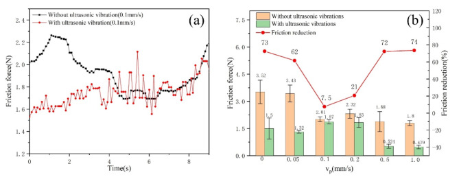
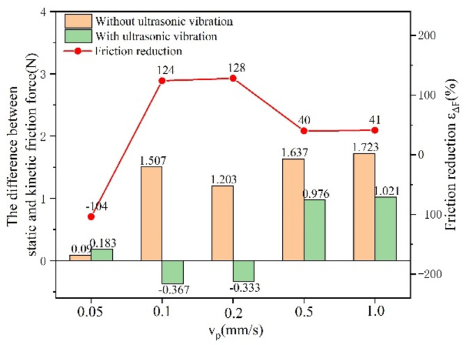
Figure 9a shows the kinetic friction curve with or without ultrasonic vibration when vp = 0.1 mm/s. When ultrasonic vibration is not applied, the friction force fluctuates greatly during the entire motion. When ultrasonic vibration is applied, the friction force decreases only by about 8%, and a short-period friction pulsation is appeared (Fig. 9a). The results are consistent with the severe stick-slip phenomenon shown in Fig. 11b. In Fig. 9b, vp = 0 mm/s indicates the maximum static frictional force of the moving slider, and the ultrasonic vibration reduces the maximum static frictional force by 73%. It can be seen from Fig. 9b that under the condition of oil lubrication, the friction reduction effect of applying ultrasonic vibration on the moving slider at different velocities varies greatly, with the lowest being 7.5% (vp = 0.1 mm/s) and the highest being 74% (vp = 1.0 mm/s). The difference between static and kinetic friction force after applying ultrasonic vibration is shown in Fig. 10. When vp = 0.05 mm/s, the difference between static and kinetic friction force increases with ultrasonic vibration, resulting in a negative reduction εΔF. When vp = 0.1 mm/s and vp = 0.2 mm/s, the kinetic friction force with ultrasonic vibration are greater than the static friction force, resulting in a reduction εΔF greater than 100%. Only when the driving velocity is greater than 0.5 mm/s, applying ultrasonic vibration can reduce the difference between static and kinetic friction force. Under the condition of oil lubrication, the kinetic friction force of the moving slider is related to the sliding velocity. At the same time, the friction force also fluctuates greatly during the movement of the same velocity, which may be because the oil film changes with the movement of the moving slider during lubrication.
Fig. 9.
The influence of friction force applied with or without ultrasonic vibration under oil lubrication condition: (a) vp = 0.1 mm/s, (b) at different driving velocities.
Fig. 11.
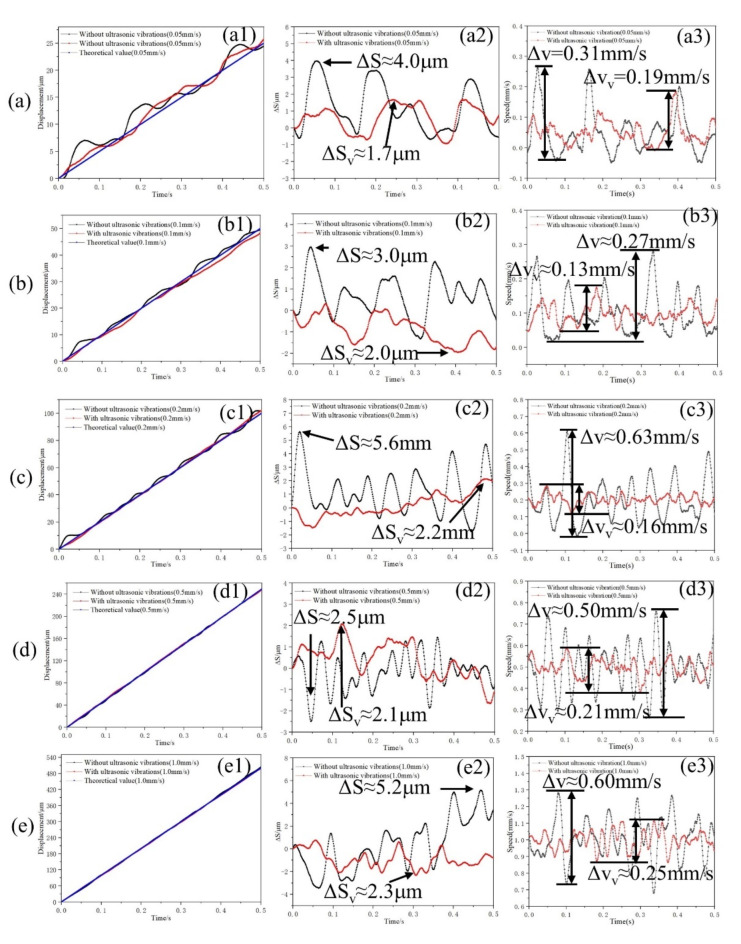
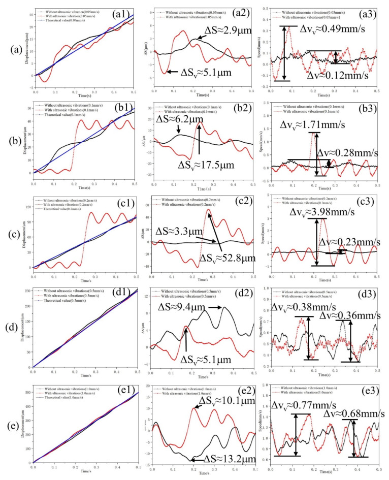
Stick-slip curves of the moving slider with or without ultrasonic vibration under oil lubrication condition: (a) vp = 0.05 mm/s, (b) vp = 0.1 mm/s, (c) vp = 0.2 mm/s, (d) vp = 0.5 mm/s, (e) vp = 1.0 mm/s.
Fig. 10.
The influence of the difference between static and kinetic friction force after applying ultrasonic vibration under oil lubrication conditions.
Figure 11 shows the stick-slip phenomenon of the moving slider during the time interval of 0.5 s at different driving velocities under oil lubrication with and without ultrasonic vibration. In Fig. 11 (a), the driving velocity of the moving solider is vp = 0.05 mm/s, and the displacement fluctuation is 2.9 μm when there is no ultrasonic vibration, and the velocity fluctuation is 0.12 mm/s, which is lower than the fluctuation under dry friction condition. When ultrasonic vibration is applied, the displacement fluctuation increases to 5.1 μm, and the velocity fluctuation increased to 0.49 mm/s, which makes more severe stick-slip phenomenon. As can be seen from Fig. 11 (b) and (c), when the driving velocity is vp = 0.1 mm/s or vp = 0.2 mm/s, the stick-slip phenomenon of the slider is significantly enhanced after applying ultrasonic vibration. As can be seen from Fig. 12, the displacement fluctuation and velocity fluctuation increase more than 15 times as much as without vibration when vp = 0.2 mm/s. When vp = 0.5 mm/s or vp = 1.0 mm/s, applying ultrasonic vibration can reduce the displacement fluctuation of the moving slider, but the velocity fluctuation is still increased. Although applying ultrasonic vibration can reduce the friction force under the condition of oil lubrication, it also makes the oil film state more complicated during the lubrication process which will result in abnormal frictional properties (εΔF < 0 or εΔF > 1) at some moving velocities, and aggravates the stick-slip phenomenon.
Fig. 12.
Stick-slip phenomenon at different driving velocities with or without ultrasonic vibration under oil lubrication condition: (a) displacement fluctuation, (b) velocity fluctuation.
Relation between Stick-slip Phenomenon and Friction Force
According to the stick-slip theory1, the critical stick-slip velocity is mainly affected by the difference between static and kinetic friction force, system stiffness, damping and workbench quality, etc. The smaller the difference between static and kinetic friction force, the smaller the critical stick-slip velocity, and the less likely stick-slip phenomenon occurs. In this paper, displacement fluctuation ΔS and velocity fluctuation Δv are used to quantify the slider’s stick-slip state. Under dry friction condition, the decrease trend of displacement fluctuation and velocity fluctuation caused by ultrasonic vibration is consistent with the decrease of the difference between static and kinetic friction force. Under oil lubrication condition, only the decrease trend of displacement fluctuation ΔS caused by ultrasonic vibration is consistent with the decrease of the difference between static and kinetic friction force. Ultrasonic vibration can greatly reduce the difference between static and kinetic friction force, and can effectively inhibit the stick-slip phenomenon.
Conclusions
Under dry friction and oil lubrication conditions, applying ultrasonic vibration can significantly reduce the static friction force and kinetic friction force at low velocity, the maximum reduction in dry friction reaches 89%, and the reduction is stable between 76% and 89% at different velocities, but the reduction fluctuates between 8% and 74% in oil lubrication at different velocities.
Under the condition of dry friction, ultrasonic vibration can greatly reduce the displacement fluctuation of the moving slider at low velocity, and stabilize the stick-slip motion at different velocities, effectively inhibiting the stick-slip phenomenon. In the case of oil lubrication, ultrasonic vibration complicates the stick-slip motion, and the stick-slip phenomenon is greatly aggravated when the driving velocity is less than or equal to 0.2 mm/s, and the stick-slip phenomenon is inhibited when the driving velocity is greater than or equal to 0.5 mm/s.
Displacement fluctuation effectively characterizes the stick-slip phenomenon of the moving slider, and its trend of variation is consistent with the reduction in the difference between static and kinetic friction forces under both dry friction and oil lubrication conditions.
Author contributions
LL wrote the main manuscript. L.L., L.N. and L.Q. completed the experiment and data curation, and prepared Figs. 1, 2, 3 and 4. CZ and WB prepared Figs. 5, 6, 7, 8, 9, 10, 11 and 12.LW and ZB proposed the conceptualization. All authors revised the manuscript.
Data availability
The datasets used and/or analysed during the current study available from the corresponding author on reasonable request.
Competing interests
The authors declare no competing interests.
Footnotes
Publisher’s note
Springer Nature remains neutral with regard to jurisdictional claims in published maps and institutional affiliations.
References
- 1.Wu, S. Analysis of machine tool stick-slip theory and stick-slip resistant design. J. Jilin Univ. Technol.02, 156–168 (1983). [Google Scholar]
- 2.Wang, X. & Wu, S. Research on the stick-slip cause of machine tool guideway (I) - analysis of the stick-slip theory of B. Э. Πyш. J. Jilin Univ. Technol.03, 64–71 (1984). [Google Scholar]
- 3.Wang, H. et al. The effect of laser surface texturing to inhibit stick-slip phenomenon in sliding contact. Adv. Mech. Eng.11 (9), 1–10 (2019). [Google Scholar]
- 4.Fridman, H. D. & Levesque, P. Reduction of Static Friction by Sonic vibrations. J. Appl. Phys.30(10), 1572–1575 (1959). [Google Scholar]
- 5.Godfrey, D. Vibration Reduces Metal to Metal Contact and Causes an Apparent Reduction in Friction. ASLE Trans. 10(2), 183–192 (1967).
- 6.Adachi, K., Kato, K. & Sasatani, Y. The micro-mechanism of friction drive with ultrasonic wave. Wear. 194 (1–2), 137–142 (1996). [Google Scholar]
- 7.Littmann, W., Storck, H. & &Wallaschek, J. Sliding friction in the presence of ultrasonic oscillations: Superposition of longitudinal oscillations. Arch. Appl. Mech.71(8), 549–554 (2001). [Google Scholar]
- 8.Kumar, V. C. & Hutchings, I. M. Reduction of the sliding friction of metals by the application of longitudinal or transverse ultrasonic vibration. Tribol. Int.37(10), 833–840 (2004). [Google Scholar]
- 9.Gutowski, P. & Leus, M. The effect of longitudinal tangential vibrations on friction and driving forces in sliding motion. Tribol. Int.55, 108–118 (2012). [Google Scholar]
- 10.Dong, S. & Dapino, M. J. Elastic-plastic cube model for ultrasonic friction reduction via Poisson’s effect. Ultrasonics. 54 (1), 343–350 (2014). [DOI] [PubMed] [Google Scholar]
- 11.Dong, S. & Dapino, M. J. Wear reduction through piezoelectrically-assisted ultrasonic lubrication. Smart Mater. Struct.23(10), 104005 (2014). [Google Scholar]
- 12.Syamsul, H., Oiwa, T., Tanaka, T. & Asama, J. Positioning error improvement based on ultrasonic oscillation for a linear motion rolling bearing during sinusoidal motion. Precis. Eng.38(3), 617–627 (2014). [Google Scholar]
- 13.Oiwa, T. Friction control using ultrasonic oscillation for rolling-element linear-motion guide. Rev. Sci. Instrum.77(1), 580 (2006). [Google Scholar]
- 14.Engel, T., Lechler, A. & Verl, A. Adaptive friction bearing for reduction of Stick-Slip Effects. Adv. Mater. Res.1018, 351–356 (2014). [Google Scholar]
- 15.Cheng, T. et al. Investigation on driving characteristics of a piezoelectric stick-slip actuator based on resonant/off-resonant hybrid excitation. Smart Mater. Struct.26(3), 035042 (2017). [Google Scholar]
- 16.Li, G. Determination of stick-slip parameters of machine tool guide. Manuf. Technol. Mach. Tool.06, 34–36 (1996). [Google Scholar]
- 17.Kumar, V. & Hutchings, I. Reduction of the sliding friction of metals by the application of longitudinal or transverse ultrasonic vibration. Tribol. Int.37 (10), 833–840 (2004). [Google Scholar]
- 18.Popov, V. L., Starcevic, J. & Filippov, A. E. Influence of Ultrasonic In-Plane oscillations on static and sliding friction and intrinsic length scale of dry friction processes. Tribol. Lett.39 (1), 25–30 (2010). [Google Scholar]
- 19.Teidelt, E., Starcevic, J. & Popov, V. L. Influence of Ultrasonic Oscillation on Static and sliding friction. Tribol. Lett.48, 51–62 (2012). [Google Scholar]
Associated Data
This section collects any data citations, data availability statements, or supplementary materials included in this article.
Data Availability Statement
The datasets used and/or analysed during the current study available from the corresponding author on reasonable request.


