Abstract
Nanotechnology has opened new avenues for advanced research in various fields of soft materials. Materials scientists, chemists, physicists, and computational mathematicians have begun to take a keen interest in soft materials due to their potential applications in nanopatterning, membrane separation, drug delivery, nanolithography, advanced storage media, and nanorobotics. The unique properties of soft materials, particularly self-assembly, have made them useful in fields ranging from nanotechnology to biomedicine. The discovery of new morphologies in the diblock copolymer system in curved geometries is a challenging problem for mathematicians and theoretical scientists. Structural frustration under the effects of confinement in the system helps predict new structures. This mathematical study evaluates the effects of confinement and curvature on symmetric diblock copolymer melt using a cell dynamic simulation model. New patterns in lamella morphologies are predicted. The Laplacian involved in the cell dynamic simulation model is approximated by generating a 17-point stencil discretized to a polar grid by the finite difference method. Codes are programmed in FORTRAN to run the simulation, and IBM open DX is used to visualize the results. Comparison of computational results with existing studies validates this study and identifies defects and new patterns.
Keywords: Computational materials, Soft matter, Diblock copolymer system, Cell dynamic simulation, Confinement
Subject terms: Materials science, Nanoscience and technology
Introduction
Nanoscience refers to the knowledge of materials at the ultra-small scale, 10nm to 100nm, and the use of this knowledge to analyze and modify materials associated with nanotechnology. Nanomaterials are a broad category of materials with unique mechanical, optical, and electrical properties. This technology has revolutionized energy harvesting, functional materials, nanoelectronics, sensors, security, and bioscience1–5. Two approaches are used for the structural development of nanomaterials, including top-down (either atom-to-atom or molecule-to-molecule) and bottom-up (self-organization) mechanisms6. Soft matter refers to a material whose properties are considered between solid and liquid. These materials include polymers, colloids, liquid crystals, and gels7.
Polymers are covalent linkages of monomers. Homopolymers consist of the same type of monomeric chain and copolymers consist of different types of monomeric chains. AB-diblock copolymers (ABDBC) are macromolecules that consist of two thermodynamically and chemically different blocks of covalently linked polymeric chains. These copolymers can create a variety of complex nanoparticles depending on their chemical composition (N), molecular characteristics (, is block A or block B), surface field environment (confinement), and block-block interactions . Experimental, material, and theoretical scientists are very interested in them. Due to the incompatibility of the two blocks, a molecule in a diblock copolymer system self-assembles and behaves in a microphase transition, giving rise to morphologies with various equilibrium order phases8–10. A diblock copolymer bulk system is empirically described by a phase diagram based on self-consistent field theory (SCFT). The phase diagram describes the microstructure and morphology of diblock copolymers. Phase separation and self-organization in the system lead to symmetry breaking, followed by the spontaneous formation of different matrices of nanostructures upon structural frustration. These morphologies are bicontinuous spheres (S), hexagonal cylinders (C), parallel lamellae (L) and complex gyroid (G)11,12.
Structural frustration is a function of block interaction , block composition f, block chain length N, block architecture, temperature, and geometry of the surface field. The SCFT presents the relationship between the degree of segregation and the volume fraction based on self-consistent field theory. Flory-Huygens interaction parameter measures the tendency for block incompatibility and segregation. At low f (one block is marginal), the block forms spherical or cylindrical domains within the matrix of the dominant block. When , the blocks form symmetric lamellar morphology with alternating layers of each block.
The product is the degree of segregation; blocks prefer to be more strongly separated. If this product is greater than a critical value (depending on block type and temperature), the system will form ordered structures. At low , the blocks are compatible and create a random mixed stat with no microphase separation. It is the border between random and organized regimes. The ordered structures in symmetric diblock copolymers are characterized by segregation and confinement strength. The blocks become sufficiently incompatible over a critical number of N (about 10-13), causing microphase separation and the formation of ordered domains. Control of the phase diagram is at the disposal of the ODT as functions of N and f in the non-linear boundaries. ODTs tune and f to produce shapes near the linear boundaries. Phase diagrams can show non-equilibrium structures during self-assembly under dynamical effects with thermodynamic equilibrium shapes12–14.
Further, Section 2 presents important related research works and points out the research gap and motivation for the current study. The proposed approach is presented in Section 3. Simulation results are discussed in Section 4 while Section 5 concludes this study.
Confinement in diblock copolymers: a review
In diblock copolymer systems (DBCS), confinement is a key element influencing self-assembly. Diblock copolymers may have a different phase behavior than bulk ones when soft materials are confined to nanopores. This has the effect of upsetting the equilibrium between confining intermolecular forces, entropy, and increasing structural frustration, which causes various kinds of phase transitions15–17. Diblock copolymers can self-assemble into multiple complicated shapes when they are contained in circular annular pores, including concentric cylinders, concentric circles, toroidal structures, and vertically aligned lamellae. The key variables in the structural regulation of soft materials are symmetry breaking, frustration, interfacial interactions, and entropy-enthalpy interactions. These characteristics, together with many other variables, such as the composition of the pores and the interactions between the diblock copolymers and the pore walls, determine the precise morphology that develops18–20.
Confinement at the nanoscale stabilizes diblock copolymer morphologies not typically observed in bulk samples, as exemplified by vertical lamellae-based surfaces. As the degree of confinement increases, the films become thinner, and the nanopores become smaller and narrower, leading to transitions from lamellae to cylinders and cylinders to spheres. This is due to the competing effects of surface interactions, chain stretching and bending, and microdomain spacing. The research demonstrates the CDS model to simulate block copolymer microphase separation over substantial areas important to applications. It also clarifies how geometric confinement affects the self-assembled nanostructures. This offers insightful molecular-level information about block copolymer thin films. The shape and orientation of the nanostructures are achieved by controlling the degree of confinement through film thickness or nanopore size21.
Tenneti explained how non-traditional morphologies of diblock copolymers may be created via 3D confinement within spherical cavities or pores, and how the morphologies can be “tuned” by changing the confinement level. The substantial confinement effects shed light on how chain stretching, surface interactions, and accessible volume influence the choice of microstructure and spacing of diblock copolymer domains. Diblock copolymers adopt different conformations as confinement and cavity radius increase, reducing their interfacial area within the confined space. As the radius gets smaller, they change from lamellae to cylinders to spheres. Confinement also causes a decrease in the distance between microdomains. Chain stretching, surface interactions, and confined volume interact to determine microdomain placement. Lamellae are formed parallel to the surface in the lower confinement. To pack more densely under increasing confinement, cylinders and spheres develop with random orientation22.
Confinement significantly affects the conformations that develop during diblock copolymer self-assembly. Stable conformations depend on various confinement effects, such as chain distortion, surface contacts, and available volume. Furthermore, there is a way to choose between different possible nanostructures by adjusting the degree of confinement. Depending on their structure, Diblock copolymers can self-assemble into nanostructures such as lamellae, cylinders, and spheres. By incorporating factors including chain distortion, surface contact, and confining volume, confinement in thin films or nanopores can change morphologies. Lamellae, cylinders, and spheres are three different shapes that change with increasing confinement23.
Block copolymer confinement significantly affects the configuration of nanoparticles in these domains. While reduced confinement can nevertheless result in better-ordered formations, high confinement restricts the mobility and organization of nanoparticles24. Morphology, which controls how colloids aggregate and pack within domains, is determined by the degree of confinement. The strength of confinement and the resulting structure is controlled by film thickness, colloid size, and interaction energy25. Cell dynamics simulations show that confinement significantly affects the microphase separation, morphologies, and orientations of diblock copolymers. More curved domains are favored by strong confinement because they can better occupy the confined space. Through a rigorous examination of confinement effects, the simulations shed light on how variables, including chain conformation, interfacial area, surface energy, and nanopattern shape, affect morphology under confinement26. As Pinna pointed out, curved geometries require stronger confinement. For this purpose, Pinna first investigated the diblock copolymers by confining them in the cartesian coordinate system and then extrapolated the results to the polar coordinate system. Polar geometries are used to achieve this goal in this research to obtain the curved confinement directly.
Confinement of the diblock copolymer melt to the substrate increases the geometrical frustration within the system, driving the self-assembly of the material to form new nanostructures that are not possible in bulk. The initial state of confinement for diblock copolymer melts is one-dimensional confinement in which the material is confined between two parallel walls. The results are the appearance of perforated holes and parallel and perpendicular lamellae patterns to the walls. In two-dimensional confinement, the material is confined between cylindrical nanopores to form helix-like nanostructures. In three-dimensional confinement, materials are confined in spherical cavities, whereby structural distortions in the materials predict toroidal morphologies. The curvature affects the topological appearance of expected results in equilibrium structures with defects27. The diffusion equation is solved using self-consistent field theory, three-dimensional spherical geometry, pseudospectral for angular coordinates in polymer concentration, and modified Crank-Nicolson method for radial direction. Field conditions are iteratively adjusted using Anderson mixing and rotational alignment techniques with adaptive parameters28.
Diblock copolymers, polar geometries, and challenges
Diblock copolymers within irregularly bound polar geometries have attracted attention in theory, finding that experimental and computational studies have encountered difficulties compared to Cartesian coordinate systems. Control connections can be simple in polar coordinates, but complex problems increase the numerical cost beyond Cartesian coordinates. Solving such issues contributes to our understanding of self-assembly in confined spaces.
Motivation and research gaps
Soft matter nanostructure control continues to be a difficult problem for theorists. The symmetry breaking of soft materials for innovative nanostructures is made possible by structural frustration, which is modified by external field confinement. This control aims to improve our ability to predict total device miniaturization, which is still difficult in coherent block systems that are restricted to circular geometries. The Laplacian is discretized with 17-point stencils in the polar mesh; innovative lamellae patterns are anticipated when this challenge is taken into account for
Contributions
In this study, some new patterns of Lamellae forming system of confined diblock copolymers are obtained under the curvature effect. This study can be utilized in material design, nanostructure fabrication, self-assembly processes, biological applications, and theoretical advancements. The numerical method for the CHC equation is a central aspect. The discussion is enhanced with the cell dynamic simulation model to clarify its significance and applicability. The detail is given as:
Material Design: Research on the effects of confinement and curvature can use these patterns to produce materials with customized properties, such as increased mechanical strength or certain thermal properties, for applications in nanotechnology and advanced engineering.
Nanostructure Fabrication: Assessing the effect of curvature and confinement on lamellae formation further stabilizes its application, which may lead to advanced fabrication techniques for nanostructures. This approach may enable the development of functional materials that are essential in electronics, photonics, and biomedical devices.
Self-Assembly Processes: The insights gained from this study may improve the prediction and control of self-assembly processes in diblock polymer systems, facilitating the design of complex architectures that are difficult to achieve by conventional methods.
Biological Applications: The findings may also inform the design of biomimetic materials that mimic natural structures, potentially influencing drug delivery systems and tissue engineering.
Theoretical Advancements: This research contributes to the theoretical understanding of polymer behavior under confinement, providing a foundation for future research.
Materials and methods
In our previous study26, we used a 9-point stencil in the polar grid system and investigated symmetric and asymmetric lamellae forming systems confined in circular annular pores with neutral and attractive walls. The grain boundary, dislocation, and disclination morphologies are common in previous and current symmetric investigations about curvature and confinement effects but the formation of patterns is different. With the increase of points of Laplacian, the patterns obtained after simulations are of mixed orientation and complex. When diblock copolymers were studied with a nine-point Laplacian for confinement and curvature effects, investigation of the interfacial walls in the pores found only concentric circles, but when the points were increased to 17, we found mixed orientation patterns in the simulation results. Concentric circles were found at low pore sizes, but by increasing the Laplacian coordinates with curvature and confinement, we also found new patterns with grain boundary, dislocation, and disinclination morphologies.
Continuous physical space can be difficult to handle computationally, so it is often discretized into a grid of discrete points, where the properties of the system are evaluated at these points.
This grid of points is called a computational space, and it is usually constructed with a uniform orthogonal structure to facilitate the use of numerically explicit finite difference schemes (FDM) used to approximate derivatives between adjacent mesh points involved in differential equations. To achieve accuracy, mesh points must be clustered in the area of larger gradients and the area of small gradients, they should be spread out to reduce computational costs. A cartesian coordinate system is not suitable for this purpose since it is uniform and orthogonal everywhere. Therefore, curvilinear coordinates generate grids with non-uniform spacing, allowing grid points to be clustered or spread out as needed29.
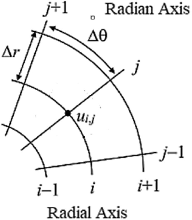
In Figure 1, the complete interpretation of the polar disc geometry is presented. In this polar coordinate system, r represent radial coordinate and for the angular coordinate . Each mesh cell is characterized by (along the radial axis of the pore) and (along the radian axis of the pore). Models created using polar coordinates more closely reflect the symmetries of block copolymer nanostructures. It is possible to increase numerical precision and stability for radial or angular issues by using spatial derivatives, such as Laplacian operators, in polar coordinates. We are excluding a section of the inner radius of the disc to address singularity issues in the geometry of the polar mesh system. We tune the variation of the outer radius to obtain different pore sizes of the disc.
Fig. 1.
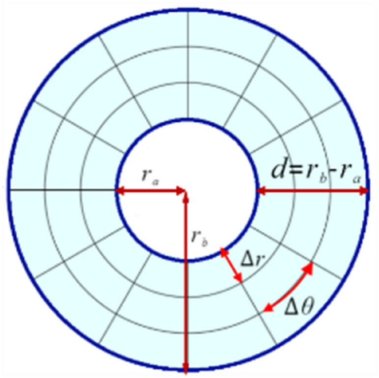
Mesh system in polar disc.
Figure 2 is evidence of the average point of the numerical scheme by discretization process in the polar mesh system. The radial dimension is discretized using a non-uniform grid and node clustering at boundaries to resolve steep gradients. N divisions between 0 and , are used to uniformly discretize the angular dimension. The is the averaging point of neighboring and nearest neighboring points at node of radial and node of the radian axis30.
Fig. 2.
Discretization in polar mesh.
Cell dynamic simulation model
The cell dynamics simulation methodology simulates spinodal decomposition and domain expansion in diblock copolymers. Under this method, the mechanics of phase separation and key aspects of morphological development are elucidated through cell evolution. On a lattice, two processes are used to analyze the time development of the order parameter. The local force brought about by the chemical potential gradient gives rise to the former. The second allows cell communication and is related to diffusional dynamics due to differences in configuration parameters between adjacent cells31.
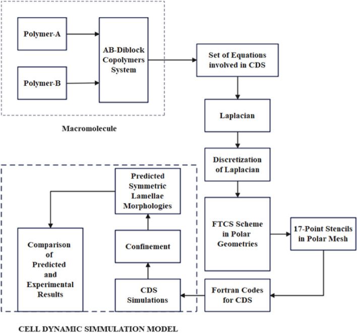
Figure 3 shows the workflow of the cell dynamic simulation model. the cell dynamic simulation model. A system of diblock copolymers is created by Polymers A and B. The average approximation of the numerical scheme for the isotropic Laplacian included in the CDS model is achieved by discretization of the macromolecule. The system initially distributes polymer segments at random and gives each cell its original composition. The system determines the chemical potential at each cell and uses numerical integration to determine the changing compositions to solve the cell equation of motion. The order parameter for the developed domain is calculated when this system tests the equilibrium. If the system is balanced, it will examine the morphology by locating the domains, calculating flaws, and measuring periodicity. When confinement is used as the surface field, more simulation-order phases are retained in the system. The Partial differential equations involved in the system are programmed in FORTRAN. The results obtained are visualized using IBM open DX.
Fig. 3.
Flow chart of cell dynamics simulation indicating the flow of the simulation as well as the processes involved in simulation.
Simulation procedure
A diblock copolymers system is considered with chains ( or ) in V volume molecule containing monomers, is a species of monomers in the form of statistical segments with scale length. The local volume fractions for two incompatible blocks in the system are
| 1 |
| 2 |
where is the density of melt connectivity, and is an incompressibility constraint32,33. At time t, the order parameter is determined for cell i of a macromolecule of DBC given as
| 3 |
where is global volume fraction fof A monomers. The rate of change in with time ensures the continuity, given as
| 4 |
In Equation 4, represents a flux (linearly related to the local chemical potential) is assumed to be
| 5 |
where M is the positive Onsager coefficient which describes the mobility of the monomer A concerning the monomer B. This chemical potential is obtained with a functional derivative of the free energy as follows.
| 6 |
The time evolution of the is described by the CHC (Cahn-Hilliard-Cook) equation34,35
| 7 |
In Equation 7, we set , representing the mobility coefficient.
The CHC equation couples to a chemical potential that depends on spatial gradients of via an interaction term. Minimizing the free energy drives the system toward equilibrium microphase separation. The free energy functional is represented by the equation36.
| 8 |
In 6, the first term is a short-range interaction term, while the second terms denote the short and long-range interaction terms. D is the diffusion constant and the is a green function that satisfies The parameter B introduces a chain-length dependence on the free energy given as37,38:
| 9 |
The temperature parameter is represented by , while A, v, and u are phenomenological constants related to molecular characteristics related to molecular characteristics. These parameters can be associated with molecular characteristics. The expressions for , D, and B are given by:
| 10 |
and
| 11 |
| 12 |
| 13 |
where is an interactive parameter and is inversely proportional to the temporal parameter, N is polymerization, b is the length of the segment, degree, is an empirical fitting function39–41.
For numerical evolution of the CDS order parameter is given below42
| 14 |
where
| 15 |
where ) is Isotropized discrete Laplacian in polar and and are polar coordinates with t time steps for order parameters.
In case of confinement
| 16 |
The boundary conditions are and is mutual interaction strength between blocks and walls, is Kronecker delta37.
The discretization of free energy function is given by
| 17 |
The Laplacian in polar form
| 18 |
where with for . and with for .
A continuum molecule of the diblock copolymer system is converted into discrete set-off points and the discretization process is carried out for Laplacian involved in the CDS model in the polar mesh through the finite difference method. The discrete 17-point isotropic stencils of Laplacian in the polar grid are given in Figure 4.
Fig. 4.
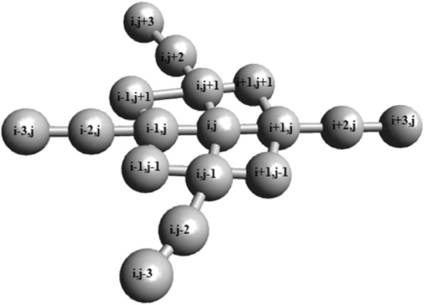
17-point discrete macromolecule of diblock copolymers system confined in annular circular pore with averaging point , neighboring points N, nearest points NN, nearest neighboring points NNN.
First-order approximation of the partial derivative for the points at the location and given in Figure 4, along the radial axis, given as
| 19 |
First-order approximation of the partial derivative for the points , , , (i, j), , and given in Figure 7, with respect to r, given as:
| 20 |
Using Taylor series approximations, we have:
Implies, the equation (20) can be written as:
| 21 |
| 22 |
Comparing the Coefficient in Equation (21), the system of equations given as:
Implies, solving the system of equations:
After that, The equation (20) becomes
| 23 |
Following the similar procedure:
First-order approximation of the partial derivative for the points at the location and given in Figure 7, along the radial axis, given as
| 24 |
| 25 |
Second-order approximation of the partial derivatives for the points and given in Figure 4, along the radial axis, given as
| 26 |
Second-order approximation of the partial derivative for the points ,, , (i, j), , and given in Figure 7, along the radial axis, given as
| 27 |
Second-order approximation of the partial derivatives for the points and given in Figure 7, along the radial axis, given as
| 28 |
| 29 |
Second order approximation of the partial derivatives for the points and given in Figure 4, along the radian axis, given as
| 30 |
Second-order approximation of the partial derivative for the points ,, , (i, j), , and given in Figure 4, along the radian axis, given as
| 31 |
Second order approximation of the partial derivatives for the points and given in Figure 4, along the radian axis, given as
| 32 |
| 33 |
Now for the approximation of Laplacian involved in the CDS model, put 25, 29 and 33 in 18 and get
| 34 |
Implies for equation 14,
| 35 |
Equation 35 is isotropic discrete Laplacian on a 17-point stencil using a polar grid obtained by a finite difference scheme. The isotropic Laplacian is used in the form for the cell dynamic simulation model43. The Laplacian is invariant under rotation in two-dimensional space44. The addition of diagonal points makes stencils more efficient45. Increasing points in Laplacian makes the Laplacian operator accurate to the exact solution46. The 17-point stencil is reported isotropic47. The exact isotropy of stencils formed in polar geometry is indeed very difficult to obtain due to curvature effects. Therefore, we have solved this problem in cells such that anisotropy is also avoided if exact isotropy is not obtained. and in the cells should be set in such a ratio that the isotropy value is closest to the exact isotropy, and the anisotropy is too far away. In this computational modeling of diblock copolymer melts confined in annular circular pore with interior radius , exterior radius and pore size . The criteria for obtaining isotropy are set as: . If , and , this ratio becomes 1.9, acceptable in the range of isotropy.
The cell dynamic simulation model essentially provides isotropic computational results. This study uses a proper method to discretize the isotropic Laplacian operator in a polar mesh system. Including more contributions from the next nearest-neighbor cells adds more accuracy and isotropy compared to our previous results. Since CDS provides large-scale simulations, it may contain very few defects in the simulation results. Numerical studies cannot provide perfect isotropic results, including small and negligible directional bias. The computational results obtained from this study are consistent with experimental and computational studies in the literature.
Here, waiting factor for neighboring nearest neighboring points is . The internal radius is fixed at or and to avoid issues of singularities, and the size of varies according to the size of pore d. Hence (35) is required isotropic discretized numerical scheme involved in cell dynamics simulation.
The periodic boundary conditions are applied on the angular coordinate of the polar mesh for evaluation of the Laplacian operator in the polar mesh system, given as:
, , for all
The reflective boundary conditions are applied on the radial coordinate for calculations of the Laplacian in the polar mesh system, given as:
, , for all .
In these boundary conditions, is approximation of order parameter , where and . The initial condition for the system of order parameter
Simulation and results
Simulations can provide insights into the behavior of diblock copolymers, such as their phase separation, self-assembly, and morphological transitions. The simulations can reveal how the polymer chains segregate into different phases and how the morphology of the resulting structures depends on factors such as temperature, pressure, and composition38. We have investigated discrete macromolecules consisting of diblock copolymer systems in polar geometries in two phases. The first phase is binary fluid simulation, and the second phase is the simulation of the Lamellae forming system with neutral and attractive walls, respectively. Binary fluid simulations model the diblock copolymer system as a mixture of two immiscible fluids representing the two polymer blocks. In these simulations, the interactions between the polymer chains and the solvent molecules are modeled using intermolecular potential functions. The resulting equations of motion are then solved numerically to obtain a time-evolving picture of the system.
Computational setup
The computational study in the manuscript is carried out by applying reflective boundary conditions in the radial direction and periodic boundary conditions in the angular direction. If the function goes outside the exterior or interior radius, the following imposed conditions (as shown in Figure 5) repel it back to within the grid size.
| 36 |
| 37 |
Fig. 5.
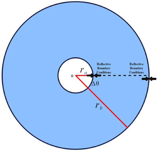
Imposed boundary conditions.
Similarly, the computation imposes the following boundary conditions (as shown in Figure 6) for the angular input.
| 38 |
| 39 |
Fig. 6.
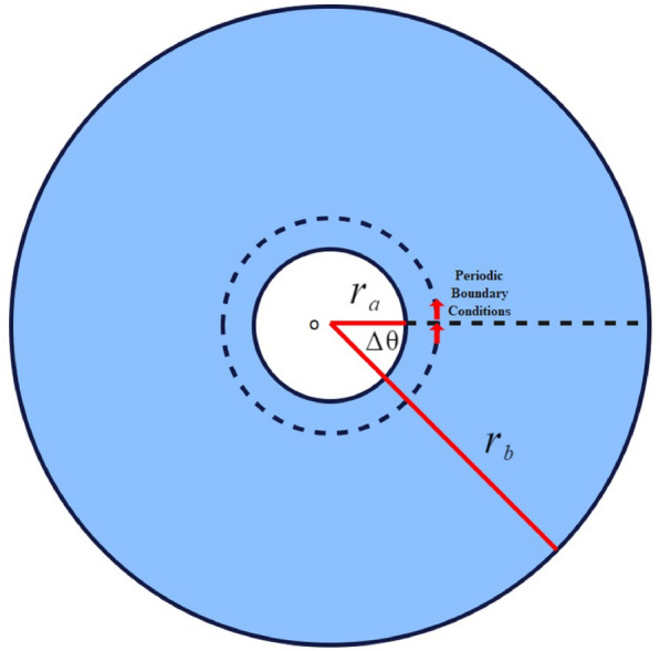
Imposed boundary conditions for angular input.
In this study, the reflective boundary conditions imposed on the radial direction and periodic boundary conditions imposed on angular coordinates ensure that no flux generation occurs in computational results.
Simulation details
All the CDS simulations were carried out using periodic boundary conditions in the angular direction , where the angular step is taken , and reflective boundary conditions were applied in radial r direction. The pore is contained between two concentric circles where the interior radius of the pore system is fixed at 3, 5, and 7 in three types of pore systems, and the exterior radius of the pore system was varied for different values to expand the pore size of the system. Therefore, circular annular pore size becomes d, where d represents the pore size of the system. The simulation results were obtained on 1 million time steps.
Evaluation of pore size in circular annular pore using CDS model
The circular annular pore is composed of a space between two concentric circles, numerically defined by a polar coordinate system. The internal radius of the pore is kept fixed, say, . The external radius is kept to vary to extend various pore sizes. The pore size is evaluated by . In the pore size , the internal radius is fixed at , and the external radius is as shown in Figure 7. In Table 1, .
Fig. 7.
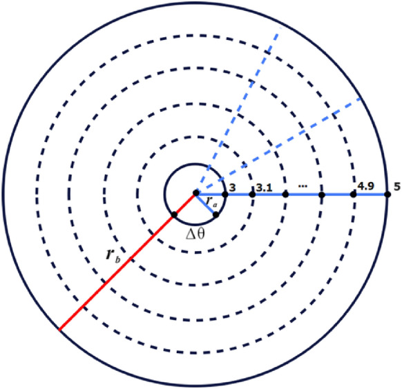
Evaluation of grid points and pore size in cell dynamic simulation of diblock copolymer melts.
Table 1.
CDS parameters for the development of lamellae forming system.
| A | B | D | u | v | f | |||||
|---|---|---|---|---|---|---|---|---|---|---|
| 1.50 | 0.00 | 0.50 | 0.50 | 2.30 | 0.50 | 0.36 | 0.1 | 0.10 | 0.00 | 0.017453292 |
In the computational set-up of the polar grid system, is the real variable used for changing radius r in the system. The value of is computed from the relation , where i is a discrete variable of the polar grid system. The pore size is For
...
...
There are 20 grid points on the radial line and 360 grid points on the circumference of each circle, for a total of points in the system (Figure 7).
Binary fluid simulation and predictions
In the first phase, binary fluid simulations examine the binary mixtures of diblock copolymer systems in polar geometries. The binary fluid simulation is obtained by tuning parameter . This simulation studies macrophase separation in a pore system instead of microphase separation. The simulation is run for 1000000-time steps, and the results provide insight into the minimum energy state the system could achieve.
Table 1 shows the values of various parameters of the CDS model on which the simulations are carried out while Figures 8 show the visual results of the binary fluid for different grid sizes on these parameters.
Fig. 8.
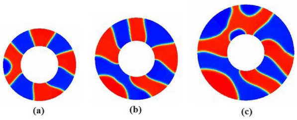
Macrophase separation for binary fluid obtained on 1000000-time steps, in a pore system with the interior radius of the pore system was fixed at and the grid sizes are (a) (b) and (c) .
In Figure 8 (a), (b), and (c), the internal radius is fixed . The results of binary fluid simulations are obtained at the grid sizes in Figure 8(a), in Figure 8 (b), and in Figure 8 (c). The external radius of the pore in Figure 8 (a), (b), and (c) vary by 6, 7, and 8, respectively, to extend the pore size d by 3,4, and 5. Here, the pore sizes are evaluated by .
The simulation result indicates that the domain distinctly separates into two subdomains with high concentrations (red rich for Polymer A and blue rich).
Simulation of lamellae forming system with neutral walls
According to simulation, both blocks have a similar attraction for walls, which results in polar cells with A/B-rich lamellae domains. Based on surface interactions at various pore sizes, lamellar spacing, and width change in response to repulsions, attractions, chain connectedness, and surface interactions.
Table 2 shows the values of the parameters used in the lamellae-forming simulation for neutral walls. Different pore sizes are outlined within two concentric circles. The domain for periodic boundary conditions is applied in the radian domain and reflective boundary conditions are applied in the radial domain. The computational domain in block A is red rich while the computational domain in block B is blue rich. For neutral walls simulation, the interactive strength between the walls and one of block A or block B is set at zero.
Table 2.
CDS parameters for developing lamellae forming system with neutral walls.
| A | B | D | u | v | f | |||||
|---|---|---|---|---|---|---|---|---|---|---|
| 1.50 | 0.20 | 0.50 | 0.50 | 2.30 | 0.50 | 0.36 | 0120 | 0.10 | 0.00 | 0.017453292... |
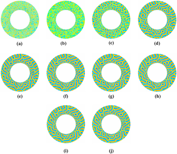
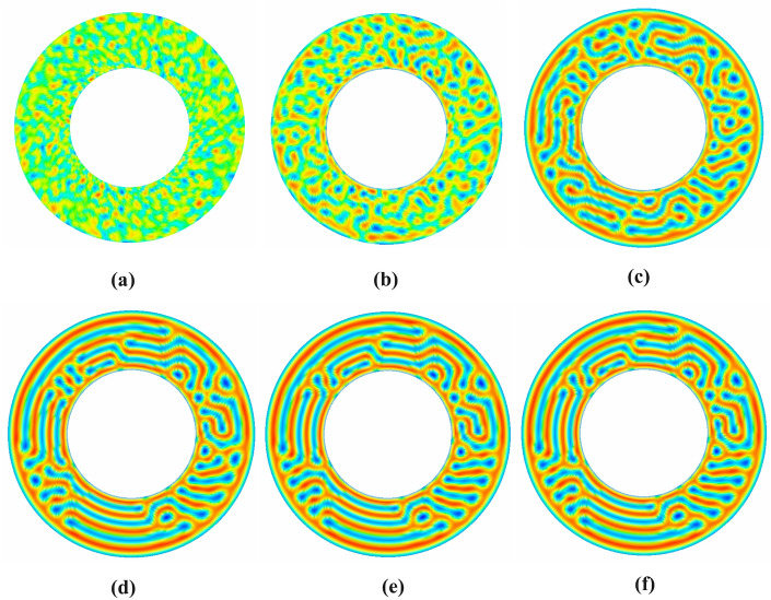
Figure 9 shows the symmetric lamellae system with neutral walls presented in various time steps in a circular annular pore with internal radius and grid size . Predicted patterns are recorded at different time steps while the simulation is repeated up to a million times.
Fig. 9.
Evaluation of symmetric lamellae system confined in annular circular pore with interfacial walls strength , having fixed internal radius , fixed external radius , grid size on various time steps: (a) time-step 0, (b) time-step 10 (c) time-step 100 (d) time-step 1000,(e) time-step 10,000,(f) time-step 50,000, (g) time-step 100,000 (h) time-step 500,000, (i) time-step 750,000, (j) time-step 1000,000.
These evaluations are precited by cell dynamic simulation during time intervals in (a), in (b), in (c), in (d), in (e), , in (f), in (g), in (h), in (i) and in (e), respectively. Blocks are dispersed and mixed at random during the initial time steps. However, as the simulation goes on, blocks with strong connections start to separate and form domains, despite the absence of any clear morphology. The size and definition of domains increase, but their randomness remains. After some time, the blocks self-assemble into an equilibrium lamellar morphology with alternating layers of each block. More parallel and uniformly spaced layers develop. The equilibrium stage is evident at the 100,000 time step. This reflection is also presented in the graph of minimization of the free energy functional, shown in Figure 10.
Fig. 10.
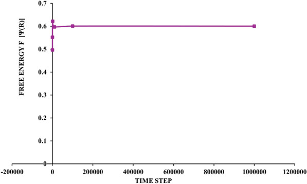
The graph of free-energy functional.
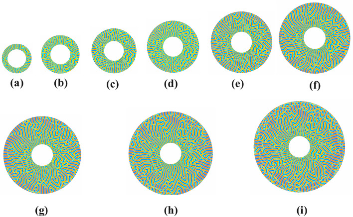
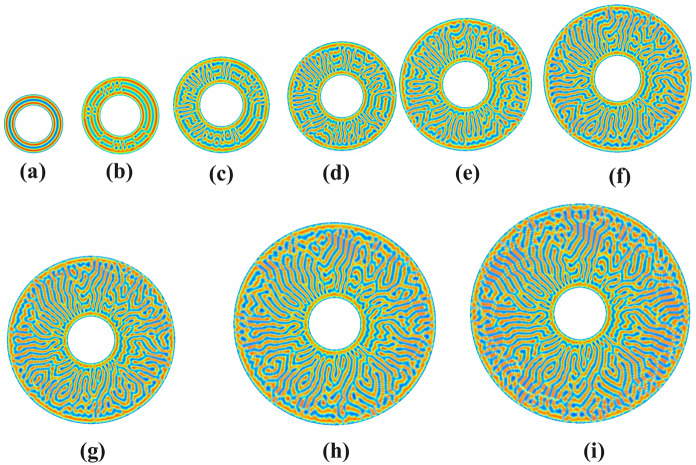
In Figure 11, the lamellar morphology of a symmetric diblock copolymer system in a polar disc is investigated for different pore sizes . The external radius of the pore varies in the ranges depending on the pore size of the annular circular pore. The internal radius of the pore is fixed at . The simulation is carried out in one million time steps. From the simulation results, it is observed that the lower pore size has some perforated pores, the number of which increases as the pore size increases or the symmetry is broken. The deformation process starts, and open lamellae and dumbly-like patterns are observed. Some V-type patterns are observed. With increasing grid size, a transition from a V-type pattern to a U-type pattern can also be observed. As pore size increases, a tilted U-type pattern is observed, followed by W-type and Y-type patterns. A further increase in pore size causes an increasing frequency of parallel and perpendicular lamellae on the outer surface of the disc with combinations of tilted U, V, and Y-lamellae morphologies.
Fig. 11.
Evaluation of symmetric Lamellae forming system on 1000000-time steps confined in annular circular pore of sizes d=2,3,4,5,6,7,8,9,10 with interior radius fixed at and variable exterior radii (a) , (b) , (c) , (d) , (e) , (f) , (g) , (h) and (i) having neutral walls.
Figure 12 investigates the lamellar morphology of the symmetric diblock copolymer system in the polar disc for various pore sizes . The annular circular pore’s internal radius, , and the range of outward radius is . The simulation results show that parallel strips of lamellae appear in the lower grid size in the lower half, and some Y-type patterns are also present. It can be seen that there are also some y-patterns between the parallel stripes. Some V-type, dumbly-type, and -type patterns are also found. As the grid size increases, some parallel bands appear to change the shape of the curve. A further increase in grid size leads to deformation in parallel lamella patterns mirrored with Y-patterns. Initially, no perforated holes were found, but as the pore size increased, the number of perforated holes gradually increased in frequency to form open-ended lamellae. Then, these open-ended lamellae are associated with V and Y patterns. Further increasing the pore size shows the transition of parallel stripes to curved stripes along the radial axis and other patterns to tilted patterns. Due to symmetry breaking, the deformation of holes and strips increases, and the trend of strips parallel to the pore changes to the perpendicular trend of the pores. Some zig-zag patterns and Moroccan U-type pattern formations can be seen clearly on the outer side of the discs.
Fig. 12.
Evaluation of symmetric Lamellae forming system on 1000000-time steps confined in annular circular pore of sizes d=2,3,4,5,6,7,8,9,10 with interior radius fixed at and variable exterior radii (a) , (b) , (c) , (d) , (e) , (f) , (g) , (h) and (i) having neutral walls.
Figure 13 examines the symmetric diblock copolymer system’s lamellar morphology for various pore diameters . The annular circular pore’s internal radius, , its exterior radius, , ranges .. The results show that some stripes parallel to the radial are visible at lower pore sizes in the top and bottom halves of the discs. Perforated holes are not visible in these initial pore sizes, but dimples are visible. At larger disc grid sizes, the complexity of the pattern increases, and geometrically symmetrical lamellae appear to form. Elongated curved lamellae are seen on the inner and outer diameters of the disc, and between them, various patterns, V-type, tilted V-type, U-type, tilted U-type, and some omega-type patterns are seen.
Fig. 13.
Evaluation of symmetric Lamellae forming system on 1000000-time steps confined in annular circular pore of sizes d=2,3,4,5,6,7,8,9,10 with interior radius fixed at and variable exterior radii (a) , (b) , (c) , (d) , (e) , (f) , (g) , (h) and (i) having neutral walls.
Simulation of lamellae forming system with attractive walls
Symmetric diblock copolymers, with one block favoring the walls, self-assemble into lamellae between attractive walls. Lamellae spacing and ordering are influenced by interaction strengths, thickness, temperature, and wall attraction, all of which play a role in lamellae morphological progression.
Table 3 shows the values of the parameters used in the Lamellae forming simulation with attractive walls.
Table 3.
CDS parameters for developing lamellae forming system with attractive walls.
| A | B | D | u | v | f | |||||
|---|---|---|---|---|---|---|---|---|---|---|
| 1.50 | 0.20 | 0.50 | 0.50 | 2.30 | 0.50 | 0.36 | 0120 | 0.10 | 0.02 | 0.017453292 |
In Figure 14, a simulation is presented for a symmetric lamellar system along with attractive walls in a circular annular pore at different time steps. Inner radius , the strength of attractive walls is and grid size is set to 30360. The visual evaluations are precited during time intervals in (a), in (b), in 6(c), in (d), in (e), and in (f), respectively. The simulation is carried out at a maximum of 1000000-time steps. Due to increased structural distortion due to confinement, new ordered structures have emerged, which are described in different pores.
Fig. 14.
Evaluation of symmetric lamellae system under one-dimensional confinement in annular circular pore with interfacial walls strength having fixed internal radius , fixed external radius , grid size on various time steps: (a) evaluation of symmetric lamellae forming system in pore size on the time-step 10, (a) evaluation of symmetric lamellae forming system in pore size on the time-step 100, (b) evaluation of symmetric lamellae forming system in pore size on the time-step 1000, (c) evaluation of symmetric lamellae forming system in pore size on the time-step 10000, (d) evaluation of symmetric lamellae forming system in pore size on the time-step 10, (e) evaluation of symmetric lamellae forming system in pore size on the time-step 100000, (f) evaluation of symmetric lamellae forming system in pore size on the time-step 1000000.
In Figure 14, a simulation is presented for a symmetric lamellar system along with attractive walls in a circular annular pore at different time steps. Inner radius , the strength of attractive walls is and grid size is set to . The visual evaluations are precited during time intervals in (a), in (b), in 6(c), in (d), in (e), and t=1000000 in (f), respectively. The simulation is carried out at a maximum of 1000000-time steps. Due to the increase in structural distortion due to confinement, new ordered structures have emerged, which are described in different pores.
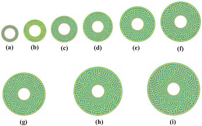
In Figure 15, we investigate a symmetric diblock copolymer system with attractive circular walls in circular annular pores of varying sizes with the internal radius of the pore kept fixed at . The external radius of the pore ranges , depending on the pore size of the annular circular pore. The morphology evolves depending on the pore size and preferential wall attraction. Looking at the simulation results in Figure 14, concentric circles at pore size d=2 are observed. However, as the pore size increases d=3, the concentric circles turning into parallel strips along the radial and radian axis are seen. As the pore size increases to d=4, some perforated holes change into stripes. When d=5, new open-ended holes are formed, and the U-type pattern meets the open-ended pattern to create an alternating U-pattern. With further increase in pore size to d=6, the parallel stripes appear to become disordered mixed with u- and v-patterns to form W-type patterns. The complexity of the patterns increases at d=7, and the joining of curved strips is seen to form transverse lamellae in the longitudinal direction. At the largest pore sizes, such as d=8,9 and 10, perforated holes appear to increase along the outer edges. Some perforated holes and dumbbell patterns are visible along the outer boundary of the discs. Elongated curved lamellae with a tilted y-pattern and an alternating inverted y-pattern are also observed.
Fig. 15.
Evaluation of symmetric Lamellae forming system on 1000000-time steps under one-dimensional confinement with interfacial walls strength in annular circular pore of sizes d=2,3,4,5,6,7,8,9,10 with interior radius fixed at and variable exterior radii (a) , (b) , (c) , (d) , (e) , (f) , (g) , (h) and (i) .
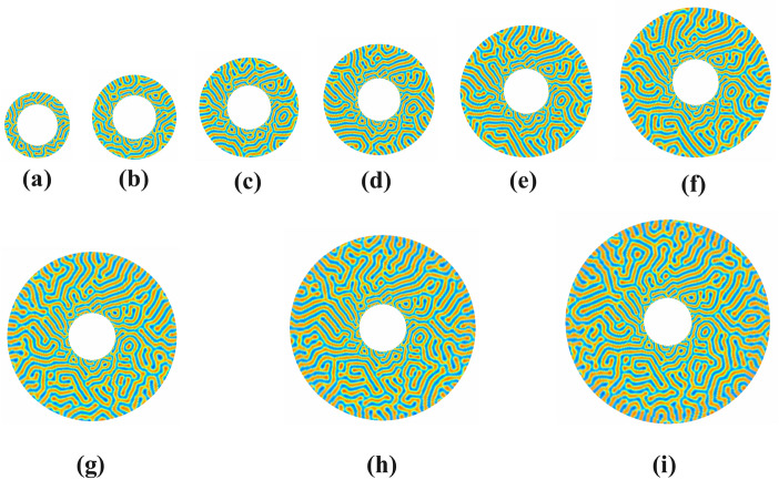
In Figure 16, the investigation is carried out by keeping the inner radius of the pore system fixed at five and the external radius of the pore ranges , depending on the pore size . At pore sizes, d=2 and d=3, concentric circular patterns are obtained due to confinement and polar geometry in the disc. Deformation of these concentric circles at pore size d=4 results in the formation of strips parallel and perpendicular to the pore and then transformed into u, v, and w patterns at pore size d=5. Perforated holes are visible in the disc at pore size d=6. A w-pattern is also seen with the combination of u and open-ended lamellae strips in pore size d=7. A look at pore sizes 8, 9, and 10 shows alternating V and W-style patterns. Longer, diagonals, more complex, and interconnected patterns are also seen near the outer boundary of the discs.
Fig. 16.
Evaluation of symmetric Lamellae forming system on 1000000-time steps under one-dimensional confinement with interfacial walls strength in annular circular pore of sizes d=2,3,4,5,6,7,8,9,10 with interior radius fixed at and variable exterior radii (a) , (b) , (c) , (d) , (e) , (f) , (g) , (h) and (i) .
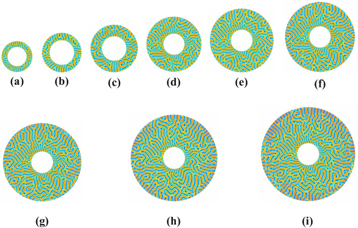
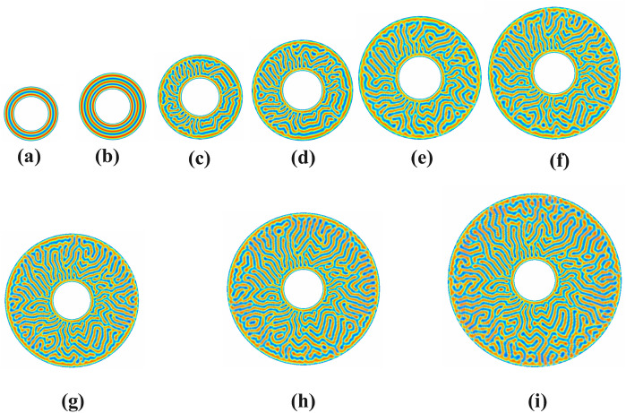
In Figure 17, the lamella morphology is constrained to the polar geometry by keeping the inner radius of the pore system fixed at and varying the external radius , depending on the pore size . The simulation results are generated at one million time steps. Looking at the simulation results in the polar disc, it is clear that confinement also plays an important role in forming new patterns along with the change in the inner radius of the disc. At pore size d=2, we get concentric circles. The deformation of the concentric circle at pore size d=3 results in the circles dissolving into perforated holes and parallel strips that are parallel and perpendicular to the pore. Small holes are also found in it. An L-type inverted L-type pattern forms upon further deformation at pore size d=4. Some perforated holes and parallel and perpendicular strips along the pore are also seen in clusters. An L-type inverted L-type pattern forms upon further deformation at pore size d=5. Some perforated holes and strips parallel and perpendicular to the pore are also seen in clusters. In pore sizes 6 to 10, holes are found around the pore walls. A few S-type patterns are also prominent, with small W- patterns and long curved strips interspersed with these patterns. Some hook-shaped patterns are also seen at extreme pore sizes. As the pore size increases, the patterns seem to increase in complexity, and the above patterns tend to become longer and more overlapping.
Fig. 17.
Evaluation of symmetric Lamellae forming system on 1000000-time steps under one-dimensional confinement with interfacial walls strength in annular circular pore of sizes d=2,3,4,5,6,7,8,9,10 with interior radius fixed at and variable exterior radii (a) , (b) , (c) , (d) , (e) , (f) , (g) , (h) and (i) .
Comparison of study with experimental studies
In contrast to experimental studies, computational modeling involves simulation techniques to model the self-assembly of block copolymers into lamellae structures and to investigate the effects of various parameters, such as pore geometry, molecular fraction, and interactions with walls, on the resulting morphologies. Both studies contribute to our understanding of the self-assembly of block copolymers; they approach the problem from different angles and provide complementary insights39–41.
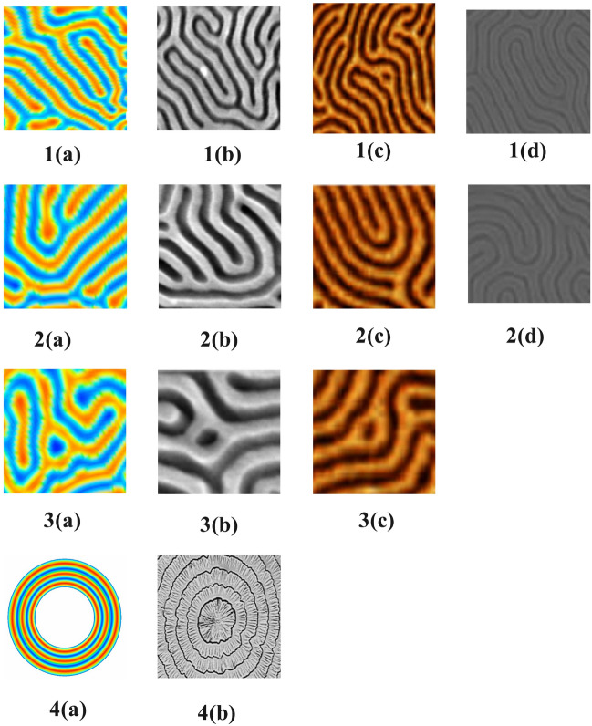
Figure 18 compares this simulation research and other research, showing that our fabricated morphologies closely resemble the morphologies of experimentally fabricated soft materials. It is clear from looking at 1(a), 1(b), 1(c), and 1(d) shapes that Y-patterns and tilted Y-patterns are seen forming as well as alternating mixed-y patterns interlaced. A look at the 2(a), 2(b), 2(c), and 2(d) shapes shows that they closely resemble an interlaced and replicated U-type and tilted U-type pattern. After observing 3(a), 3(b), and (c), it is clear that the perforated holes are similar to our investigations and experimental studies. Similarly, 4(a) and 4(b) resemble in their concentric circles. In addition to experimentally similar morphologies, this investigation has also revealed some morphologies that better illustrate the significance of this work.
Fig. 18.
Comparison of our predicted lamellae morphologies (a) with experimental studies, (b) Plasma etch transfer of self-assembled polymer patterns48, (c) The morphology of ordered block copolymer patterns as probed by high-resolution imaging49 and (d) Study of the ordered assembly morphologies of diblock copolymers on the same substrate50.
In26, symmetric diblock copolymers were investigated with a cell dynamic simulation model to evaluate the effects of confinement and curvature with a nine-point Laplacian approximation. Symmetric investigation revealed grain boundary, dislocation, and disinclination morphologies in the configuration of the neutral wall during confinement, but only concentric circle patterns were found during confinement in the configuration of the interfacial wall. In this symmetric study, when the points were increased to 17, mixed orientation patterns were found in the simulation results. During the neutral walls phase, the mixed orientation of patterns was found, including dislocation, disclination, and dislocation morphologies. Few concentric circles were obtained at low pore sizes in the confinement phase with attractive walls. Some new patterns and defects in Lamellae patterning are also observed significantly.
This study is carried out with fixed volume fractions, and Lamellae size varies concerning radius due to characteristics of the polar grid. However, fat in size. This study appreciates frustration, as Lamellae forms rich patterns compared to computational studies. This study with 2D Confinement i-e (confined in circular annular pores and employing attractive walls) is consistent with the studies in27. The topology of curved planes and surfaces enforces the defect structures in the equilibrium phases with different radii. The predicted results in this investigation appear in dislocation and disclination morphologies, similar to27 but different in nature of patterns (discussed in detail in Figure 18. Moreover, grain boundary morphologies were also observed.
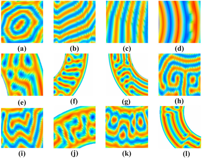
Considering the simulation results, it is found that pore size, curvature, and confinement have left their effects on the lamella forming system and some new lamella patterns ( (a), (b), (c), (d), and (i) have emerged and defect patterns ( (e), (f), (g), (h), (k) and (l) have also been observed.
In Figure 19, the morphologies are observed in the form of hexagonal Lamellae peaking with deforming perforated hole (a), Lamellae parallel to the radial axis of the pore (b), Lamellae perpendicular to the radial axis (c), Concentric Lamellae (d), Perforated hole surrounded by reformatted perforated holes along the pore (e), Deformation of perforated holes perpendicular to the pore (f), Expansion of deformed perforated holes parallel and perpendicular to the pore (g). A tilted T or Tau morphology (h), Alternating W-patterns (i), Reflected L- Lamellae (j) Alternating perforated holes in the edges of square wave-like morphology (k) Alternating strips of hockey shape with deformed perforated holes.
Fig. 19.
The new predicted Lamellae morphology of symmetric diblock copolymers system confined in circular annular pore (a), (b), (c), (d), and (i) with defects in predicted morphology (e), (f), (g), (h), (j), (k) and (l).
Limitations of study
The simulation of diblock copolymer systems at finite geometries can be influenced by the size of the system and by constructing a discretized numerical scheme for the Laplacian at higher points. The internal pore size cannot be initialized to zero, otherwise, singularity problems may occur and the numerical scheme becomes undefined.
Conclusions
The alternating curved patterns of the AB-diblock copolymer system confined into circular annular pores are exhibited and analyzed in this study. To accomplish predicted visuals of phase diagrams of these patterns, rigorous new numerical formulations for approximation of the set of partial differential equations involved in the Cell dynamic Simulations model, are carried out in this study using a polar mesh system. Using existing approximated formulations for partial derivatives, a novel numerical formulation for the approximations of the Laplacian operator on 17-pint stencil is successfully presented in this contribution which is useful in numerically solving partial differential equations on polar mesh system. New formulations of physically motivated partial differential equations and Laplacian functional approximations are carried out on the challenging polar mesh system to avoid singularity issues in the center and its neighborhood during the discretization. This computational study reveals and showcases novel patterns of symmetric AB-Block copolymers confined into a circular disc. The curved alternating strips of symmetric AB block copolymer system mold into different shapes due to the effect of curvature and frustration of nano-particles. Computational results on different pore sizes show distinct patterns in the disc, including perforated holes, Y-shaped, tilted Y-shaped, V-shaped, tilted V-shaped, W-shaped, U-shaped, T Shape, tau shape, L-shaped, tilted L-shaped and dimple-like pattern. Phase diagrams of the alternating symmetric AB-block copolymer system with small pore sizes conform to more frequent perforated holes and alternating strips parallel to the radii of the pore. In contrast, appreciated pore size conforms to open-ended lamellae. The symmetry breaking in the confined AB-block copolymer system promotes perpendicular to the pore alternating strips. Appreciated pore sizes weaken the curvature effect on the lamellae morphology; consequently, the randomness of curved alternating strips and elongated curved lamellae into the disc conforms. The confining symmetric diblock copolymer into a disc, placing interfacial circular walls and small pore size conforms perfect alternating concentric circles in the pore domain due to the curvature and interaction of the nano-particles.
New morphologies of diblock copolymer systems can be explored in the future by creating a two-dimensional confinement system with a three-dimensional numerical scheme.
Author contributions
MJI conceived the idea, performed data curation, and wrote the original manuscript. IS conceived the idea, performed formal analysis, and wrote the original manuscript. MAR designed the methodology and performed formal analysis and data curation. EOM acquired funding and performed investigation and project administration. ZLVM dealt with software, visualization, and validation. IA supervised the work, performed validation, and edited the manuscript. All authors reviewed the manuscript.
Funding
This study is supported by the European University of Atlantic.
Data availability
The data generated in this study can be requested from Muhammad Javed Iqbal.
Declarations
Competing interests
The authors declare no competing interests.
Footnotes
Publisher’s note
Springer Nature remains neutral with regard to jurisdictional claims in published maps and institutional affiliations.
References
- 1.Doi, M. Soft Matter Physics (Oxford University Press, USA, 2013). [Google Scholar]
- 2.Selinger, J. V. Introduction to the Theory of Soft Matter: from Ideal Gases to Liquid Crystals (Springer, 2016). [Google Scholar]
- 3.Hamley, I. W. Introduction to Soft Matter: Synthetic and Biological Self-assembling Materials (John Wiley & Sons, 2007). [Google Scholar]
- 4.Singh, A., Dubey, S. & Dubey, H. K. Nanotechnology: The future engineering. Nanotechnology 6(2), 230–233 (2019). [Google Scholar]
- 5.Pandey, P. et al. Role of nanotechnology in electronics: A review of recent developments and patents. Recent patents on nanotechnology 16(1), 45–66 (2022). [DOI] [PubMed] [Google Scholar]
- 6.Hu, X.-H. & Xiong, S. Fabrication of nanodevices through block copolymer self-assembly. Frontiers in Nanotechnology 4, 762996 (2022). [Google Scholar]
- 7.Hu, X.-H. & Xiong, S. Fabrication of nanodevices through block copolymer self-assembly. Frontiers in Nanotechnology 4, 762996 (2022). [Google Scholar]
- 8.Deshmukh, O. S. Soft Microgel Particles at Fluid Interfaces. University of Twente, (2015)
- 9.Diaz, J., Pinna, M., Zvelindovsky, A. V. & Pagonabarraga, I. Nematic ordering of anisotropic nanoparticles in block copolymers. Advanced Theory and Simulations 5(1), 2100433 (2022). [Google Scholar]
- 10.Hamley, I. Nanotechnology with soft materials. Angewandte Chemie International Edition 42(15), 1692–1712 (2003). [DOI] [PubMed] [Google Scholar]
- 11.Cummins, C. et al. Enabling future nanomanufacturing through block copolymer self-assembly: A review. Nano Today 35, 100936 (2020). [Google Scholar]
- 12.Nisticò, R. Block copolymers for designing nanostructured porous coatings. Beilstein journal of nanotechnology 9(1), 2332–2344 (2018). [DOI] [PMC free article] [PubMed] [Google Scholar]
- 13.Rosedale, J. H., Bates, F. S., Almdal, K., Mortensen, K. & Wignall, G. D. Order and disorder in symmetric diblock copolymer melts. Macromolecules 28(5), 1429–1443 (1995). [Google Scholar]
- 14.Li, C. et al. Self-assembly of block copolymers towards mesoporous materials for energy storage and conversion systems. Chemical Society Reviews 49(14), 4681–4736 (2020). [DOI] [PubMed] [Google Scholar]
- 15.Tseng, Y.-C. & Darling, S. B. Block copolymer nanostructures for technology. Polymers 2(4), 470–489 (2010). [Google Scholar]
- 16.Shi, A.-C. & Li, B. Self-assembly of diblock copolymers under confinement. Soft Matter 9(5), 1398–1413 (2013). [Google Scholar]
- 17.Bae, S., Noack, M. M. & Yager, K. G. Surface enrichment dictates block copolymer orientation. Nanoscale 15(15), 6901–6912 (2023). [DOI] [PubMed] [Google Scholar]
- 18.Mendoza, C., Nirwan, V. P. & Fahmi, A. Nanofabrication of hybrid nanomaterials: Macroscopically aligned nanoparticles pattern via directed self-assembly of block copolymers. Journal of Applied Polymer Science 140(5), 53409 (2023). [Google Scholar]
- 19.Hu, D., Chang, X. & Zhu, Y. Engineering the morphologies of block copolymer particles from the confined self-assembly within emulsion droplets. Chinese Journal of Chemistry 41(2), 237–245 (2023). [Google Scholar]
- 20.Schmarsow, R. N. et al. Supramolecular networks obtained by block copolymer self-assembly in a polymer matrix: Crystallization behavior and its effect on the mechanical response. Macromolecules 56(4), 1652–1662 (2023). [Google Scholar]
- 21.Pinna, M. & Zvelindovsky, A. Large scale simulation of block copolymers with cell dynamics. The European Physical Journal B 85, 1–18 (2012). [Google Scholar]
- 22.Tenneti, A., Ackerman, D. M. & Ganapathysubramanian, B. Equilibrium microstructures of diblock copolymers under 3d confinement. Computational Materials Science 174, 109453 (2020). [Google Scholar]
- 23.Horechyy, A. et al. Nanoparticle assembly under block copolymer confinement: The effect of nanoparticle size and confinement strength. Journal of Colloid and Interface Science 578, 441–451 (2020). [DOI] [PubMed] [Google Scholar]
- 24.Sheng, Y., Chen, C., Xia, Y., Gao, C. & Zhang, X. Tunable morphologies from solution self-assembly of diblock copolymers under nanoscale confinement. Chemical Physics Letters 730, 361–366 (2019). [Google Scholar]
- 25.Diaz, J., Pinna, M., Zvelindovsky, A. V., Asta, A. & Pagonabarraga, I. Cell dynamic simulations of diblock copolymer/colloid systems. Macromolecular Theory and Simulations 26(1), 1600050 (2017). [Google Scholar]
- 26.Iqbal, M. J., Soomro, I., Bibi, M. & Mallah, R. N. Morphological investigation of lamellae patterns in diblock copolymers under change of thickness and confinement in polar geometry. VFAST Transactions on Mathematics 11(2), 174–197 (2023). [Google Scholar]
- 27.Zhang, L., Wang, L. & Lin, J. Defect structures and ordering behaviours of diblock copolymers self-assembling on spherical substrates. Soft Matter 10(35), 6713–6721 (2014). [DOI] [PubMed] [Google Scholar]
- 28.Vorselaars, B., Kim, J. U., Chantawansri, T. L., Fredrickson, G. H. & Matsen, M. W. Self-consistent field theory for diblock copolymers grafted to a sphere. Soft Matter 7(11), 5128–5137 (2011). [Google Scholar]
- 29.Hoffman, J. D. & Frankel, S. Numerical Methods for Engineers and Scientists (CRC Press, 2018). [Google Scholar]
- 30.Inayatullah Soomro, I. A. et al. Mathematical modelling of cylindrical forming di-block co-polymers confined in circular annular pores. IJCSNS 19(2), 16 (2019). [Google Scholar]
- 31.Hamley, I. W. Cell dynamics simulations of block copolymers. Macromolecular theory and simulations 9(7), 363–380 (2000). [Google Scholar]
- 32.Ohta, T. & Kawasaki, K. Equilibrium morphology of block copolymer melts. Macromolecules 19(10), 2621–2632 (1986). [Google Scholar]
- 33.Kawasaki, K., Ohta, T. & Kohrogui, M. Equilibrium morphology of block copolymer melts. 2. Macromolecules 21(10), 2972–2980 (1988). [Google Scholar]
- 34.Hawick, K. A., & Playne, D. P. Modelling and visualizing the cahn-hilliard-cook equation. In MSV, pp. 149–155 (2008)
- 35.Choksi, R., Peletier, M. A. & Williams, J. On the phase diagram for microphase separation of diblock copolymers: an approach via a nonlocal cahn-hilliard functional. SIAM Journal on Applied Mathematics 69(6), 1712–1738 (2009). [Google Scholar]
- 36.Bahiana, M. & Oono, Y. Cell dynamical system approach to block copolymers. Physical Review A 41(12), 6763 (1990). [DOI] [PubMed] [Google Scholar]
- 37.Hamley, I. W. Cell dynamics simulations of block copolymers. Macromolecular theory and simulations 9(7), 363–380 (2000). [Google Scholar]
- 38.Ren, S. & Hamley, I. Cell dynamics simulations of microphase separation in block copolymers. Macromolecules 34(1), 116–126 (2001). [Google Scholar]
- 39.Leibler, L. Theory of microphase separation in block copolymers. Macromolecules 13(6), 1602–1617 (1980). [Google Scholar]
- 40.De La Olvera, Cruz M. Theory of microphase separation in block copolymer solutions. The Journal of chemical physics 90(3), 1995–2002 (1989). [Google Scholar]
- 41.Pinna, M., Guo, X. & Zvelindovsky, A. V. Block copolymer nanoshells. Polymer 49(12), 2797–2800 (2008). [Google Scholar]
- 42.Feng, J. & Ruckenstein, E. Long-range ordered structures in diblock copolymer melts induced by combined external fields. The Journal of chemical physics 121(3), 1609–1625 (2004). [DOI] [PubMed] [Google Scholar]
- 43.Pinna, M. & Zvelindovsky, A. Large scale simulation of block copolymers with cell dynamics. The European Physical Journal B 85, 1–18 (2012). [Google Scholar]
- 44.Kamgar-Parsi, B. & Rosenfeld, A. Optimally isotropic laplacian operator. IEEE Transactions on Image Processing 8(10), 1467–1472 (1999). [DOI] [PubMed] [Google Scholar]
- 45.Lee, H. G., Ham, S. & Kim, J. Isotropic finite difference discrettization of laplacian operator. Appl. Comput. Math 22(2), 259–274 (2023). [Google Scholar]
- 46.Kahlaf, S. J., & Mhassin, A. A. Numerical solution of a two-dimensional laplace equation with dirichlet boundary conditions. In: Journal of Physics: Conference Series, 1818, 012193 (2021). IOP Publishing
- 47.Patra, M. & Karttunen, M. Stencils with isotropic discretization error for differential operators. Numerical Methods for Partial Differential Equations: An International Journal 22(4), 936–953 (2006). [Google Scholar]
- 48.Johnston, D. E., Lu, M. & Black, C. T. Plasma etch transfer of self-assembled polymer patterns. Journal of Micro/Nanolithography, MEMS, and MOEMS 11(3), 031306–031306 (2012). [Google Scholar]
- 49.Borah, D. et al. The morphology of ordered block copolymer patterns as probed by high resolution imaging. Nanomaterials and Nanotechnology 4, 25 (2014). [Google Scholar]
- 50.Zhang, B., Meng, L. & Li, Z. Study of the ordered assembly morphologies of diblock copolymers on the same substrate. RSC advances 12(44), 28376–28387 (2022). [DOI] [PMC free article] [PubMed] [Google Scholar]
Associated Data
This section collects any data citations, data availability statements, or supplementary materials included in this article.
Data Availability Statement
The data generated in this study can be requested from Muhammad Javed Iqbal.


