Abstract
The instability of the primary coal and rock structure significantly impacts the safety of coal mining and construction. The complex coal-rock interface cannot be simplified as a smooth surface. To investigate the dynamic response of primary composite coal and rock (primary-CCR), we studied the impact of load, hydrostatic pressure, and interface type on the mechanical behavior and macro/micro failure characteristics using a separate Hopkinson bar, a high-speed camera, and a scanning electron microscope. The results indicate a linear relationship between the composite strength, impact toughness, and impact velocity of the two types of composite coal and rock. The mechanical behavior of the primary-CCR initially increases and then decreases with the rise of hydrostatic pressure (turning point: 10 MPa). There is a positive correlation between artificial combined coal-rock (artificial-CCR) and hydrostatic pressure. The dissipative energy of combined coal and rock increases linearly with impact velocity. Initially, the dissipative energy per unit fracture area increases with hydrostatic pressure, then decreases as pressure continues to rise. Additionally, an increase in impact load causes the energy dissipation inflection point to shift forward. The primary interface significantly reduces the energy threshold for instability failure, resulting in a transition from energy transfer to energy dissipation in rock components. This transition manifests as the failure of artificial combined coal and rock cracks, which develop into rock fragments at an impact velocity of 14 m/s. Furthermore, the change in section roughness of coal and rock correlates with the degree of macroscopic crack growth, following the order: coal > primary-CCR > artificial-CCR > rock.
1. Introduction
As shallow coal resources in China become increasingly depleted, coal mining is progressively shifting to deeper levels at a rate of 10–25 m per year.1 This transition has led to deep mining becoming the new norm and has resulted in more frequent occurrences of coal and rock dynamic disasters, which can lead to significant casualties and property losses. Numerous engineering studies have indicated that the coal-rock combination serves as a critical structural component for preventing and controlling dynamic disasters associated with mining.2 This combination directly affects the stability of the surrounding rock in deep roadways and the thresholds for disaster induction. Moreover, the severity of disasters is closely related to the mechanical response processes of the coal-rock combination structure,3 as illustrated in Figure 1. Primary-CCR structures are commonly found in semicoal roadways,4 uncovering coal,5 and coal seams containing impurities.6 The complexity of coal and rock structures results in significant variations in their dynamic responses and macro- and microfailure characteristics, which are more intricate than those of single coal and rock or artificially combined coal and rock. Therefore, studying the dynamic failure behavior of primary combined coal and rock under impact loads is of great significance, as it facilitates the accurate characterization of the mechanical response mechanisms, thereby enabling the safe and efficient construction of underground rock masses and enhancing the early warning capabilities for rock mass instability.
Figure 1.
Natural boundary state of middling coal and rock in semi coal rock roadway.
The mechanical properties of coal and rock assemblages are critical factors influencing the prevention and control of dynamic disasters in coal and rock environments, making them a significant focus of research both domestically and internationally. Numerous scholars have investigated the constitutive equations,7 mechanical properties,8,9 and failure mechanisms of artificial combined rock masses in relation to coal and rock assemblages.10−12 To explore the static response behavior of coal and rock during the preparation phase of dynamic disasters, Zuo et al.13 conducted uniaxial compression experiments on coal rock combined with different combination modes to determine the influence of combination modes on impact inclination and the interaction between coal and rock. Zheng et al.14 investigated the effect of the number of layers on the compressive performance of artificial-CCR, finding that the compressive strength of the composite decreased with an increasing number of layers. Chen et al.15 developed an assembly damage model based on immersion time, suggesting that the damage effect of water in the assembly was proportional to the immersion time. Cai et al.16 obtained the static load compressive strength of rock monomer and primary-CCR. Wang et al.17 conducted a three-dimensional scan and reconstruction of the primary-CCR interface, along with developing a progressive damage model for the primary-CCR interface. Gu,18 Yin,19 and Li20 investigated the impact of interface inclination, combination, and lithology on the mechanical properties of the assembly. Furthermore, since the onset phase of coal and rock dynamic disasters represents a typical dynamic failure process,21 several researchers have examined the dynamic response mechanisms of coal and rock under high strain rates using the Split Hopkinson Pressure Bar (SHPB) system. Gong et al.22 explored the dynamic characteristics of composite rock mass under different strain rates, highlighting significant strain rate effects on the dynamic compressive strength and peak strain of coal rock combined. Han et al.23 studied the ternary coal rock combined with weak interlayers in the middle, obtaining the interlayer failure mode and mechanical response mechanism. Yang et al.24 investigated the influence of wave impedance on layered composite rock mass, concluding that the dynamic performance of composite rock mass under the influence of wave impedance is significantly different, but tends to be consistent with the increase of impact velocity. Xie et al.25,26 proposed a cascading damage constitutive model of artificial-CCR, and obtained the dynamic failure characteristics of primary-CCR under static pressure. Wen et al.27 explored the mechanical behavior and failure mechanism of composite layered rocks under dynamic tensile load.
However, coal rock combined is a heterogeneous and discontinuous anisotropic material, and the deformation and failure of the sample can only be characterized by mechanical method.28 In fact, the essence of rock mass failure is a dynamic instability process of internal energy absorption and release induced by external loads.29 Some scholars carried out studies from the perspective of energy evolution. For example, Li et al.30 studied the energy dissipation characteristics of assembly like rock mass and found that the energy accumulation degree of coal rock combined was higher and the energy threshold of inducing dynamic disasters was lower. Liu et al.31−33 studied the relationship between dynamic strength, fractal dimension and stress wave energy of composite rocks, and analyzed the energy dissipation and chaos mechanism of composite rocks under dynamic and static loading. Li et al.34 explored the energy transfer law of ore-rock-fill assemblage, and found that the absorbed energy density increased linearly with the incident energy, while the failure phenomenon of the combined sample was concentrated in the weak layer.
Existing research results focus on the study of the dynamic characteristics of artificial-CCR and rock monomer. Some scholars have carried out the study of the static characteristics of primary-CCR,35 but the study on the law of energy dissipation of primary-CCR under impact load is relatively rare. Based on this, SHPB system is used to study the energy dissipation law and macro and micro failure mode of artificial/primary-CCR under different hydrostatic pressure (axial pressure = confining pressure)36,37 and strain rate, explore the difference of impact failure of coal rock combined with fractal dimension, and analyze the microfracture characteristics of rock with scanning electron microscopy (SEM), in order to provide theoretical reference for engineering construction and protection in mines.
2. Experimental Overview
2.1. Specimen Preparation
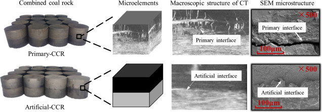
The experimental samples were collected from a mine in Xinzhou City, Shanxi Province, China. The primary-CCR was obtained from the intersection of coal and rock formations, as illustrated in Figure 2. The working face was manually sampled using air picks, and the entire transportation and sample preparation process ensured the integrity of the interface. Subsequently, a uniaxial compression experiment was conducted using an MTS servo press, yielding static compressive strength values of 35.18 MPa for the artificial-CCR and 22.36 MPa for the primary-CCR, with corresponding elastic moduli of 5.14 and 5.17 GPa, respectively. The strength characteristics indicate a relatively high presence of internal fractures in the primary-CCR samples.38 Specifically, the interface of the artificial-CCR samples appears smooth without an obvious transition area, while the primary-CCR samples exhibit a rough interface with numerous cracks traversing the sample, resulting in a relatively irregular transition area.
Figure 2.
Standard assemblage of rock samples and localized features.
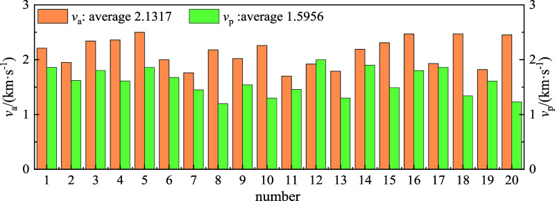
According to the regulations of China Association of Rock Mechanics and Engineering,39 large rock samples need to undergo cored, cut, grinding and other processes to meet the requirements of the end face nonparallelism ≤ 0.02 mm and nonperpendicality ≤ 0.02 mm. The size of the two types of combined rock samples is 50 mm in diameter × 50 mm in height. Coal is metamorphic rock, and rock is sedimentary rock. Among them, the primary-CCR sample should ensure that the proportion of coal and rock is relatively uniform, while the artificial-CCR sample is made of coal and rock monomer material with diameter 50 mm × height 25 mm and bonded with epoxy resin glue. Through X-ray diffraction experiments, two types of rock compositions were obtained, as shown in Table 1. Simultaneously, to ensure sample heterogeneity, the longitudinal wave velocity of the standard sample was measured using a nonmetallic ultrasonic detector, as depicted in Figure 3. The average longitudinal wave velocity (vp) of the primary-CCR is 1.60 km/s, while the velocity (va) of the artificial-CCR is 2.13 km/s, indicating a 24.88% difference. This disparity is attributed to inherent defects such as primary cracks and pores within the sample.
Table 1. Rock Type and Composition.
| sample | typology | composition |
|---|---|---|
| coal | metamorphic | kaolinite, quartz, calcite, organic matteretc |
| rock | sedimentary rock | quartz, kaolinite, boehmite, hard aluminaetc |
Figure 3.
Combined coal rock longitudinal wave velocity.
2.2. SHPB System and Principle
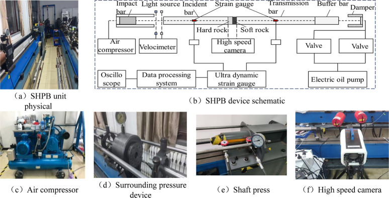
A modified φ50 mm Hopkinson pressure rod system is employed to conduct impact loading experiments on two types of composite rock masses. The SHPB system is illustrated in Figure 4. The incident rod, transmission rod, and impact rod have lengths of 3000, 2500, and 400 mm, respectively. They are made of φ50 mm cylindrical rods composed of low carbon steel with a density of 7800 kg/m3, an elastic modulus of 206 GPa, and a longitudinal wave speed of 5410 m/s. Prior to the experiment, the rods must be aligned, and subsequently, the impact speed is adjusted by controlling the air compressor’s pressure. Voltage signals from the incident wave, reflected wave, and transmitted wave were obtained using BX120-5AA and LK2017 superdynamic strain gauges attached to the bar’s surface. The experimental data were processed using the two-wave method, and the energy variation of the sample was calculated using Formulas 1–4.
| 1 |
| 2 |
| 3 |
in the formulas, WI, WR and WT represent the incident energy, reflected energy, and transmitted energy, respectively. A0, C0 and E denote the cross-sectional area, longitudinal wave velocity, and elastic modulus of the elastic rod, while σI, σR and σT represent the incident stress, reflected stress, and transmitted stress, respectively.
Figure 4.
SHPB combined static and dynamic loading system.
Per the law of conservation of energy, in the SHPB experiment, a portion of the incident wave is reflected and transmitted at the bar-specimen’s contact end face. Some of the energy is utilized for crack propagation, development, and penetration in the specimen, while a minimal portion is dissipated as kinetic energy, sound waves, radiation, and heat, which are challenging to measure. According to Literature40, energy dissipation in the form of kinetic energy, sound waves, radiation, and heat represents only 5% of the absorbed energy. Therefore, energy loss due to friction between rods and between rods and samples is disregarded during the impact process, implying that absorbed energy ≈ dissipated energy. Thus, the energy absorbed by the sample is denoted as the dissipated energy of the sample, WA
| 4 |
2.3. Experimental Plan and Stress Balance Test
2.3.1. Experimental Plan
Preimpact experiments were carried out on the two types of combined rock mass before the experiment, and the experimental results showed that significant overall damage could occur only when the impact velocity was no less than 14 m/s, so the experimental velocity V gradiants were selected as 10, 12, 14, and 16. The selection of hydrostatic pressure P is based on the ground stress test results and SHPB system performance, and the final experimental scheme is set up, as shown in Table 2.
Table 2. Experimental Plan.
| specimen type | V/(m·s–1) | P/MPa |
|---|---|---|
| artificial composite coal rock | 10, 12, 14, 16 | 0, 6, 8, 10, 12 |
| primary composite coal rock | 10, 12, 14, 16 | 0, 6, 8, 10, 12 |
2.3.2. Stress Balance Test
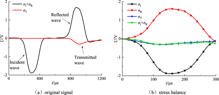
Stress balance test is an important prerequisite for judging the reliability of SHPB test results. Figure 5 shows the original waveform and stress balance diagram of the composite rock mass, where U is the voltage signal and t is the duration of the stress wave. It can be seen from Figure 5 that the superimposed wave and transmitted wave of the incident wave and reflected wave of the combined rock mass basically coincide, that is, both ends of the sample basically reach the stress equilibrium state.41
Figure 5.
Stress balance diagram.
3. Results and Discussion
3.1. Dynamic Properties
3.1.1. Combined Compressive Strength Characteristics
Reference (42) indicates that the combined strength of the sample is the sum of the preloaded static pressure and the dynamic peak stress, which reflects the actual compressive strength of the sample and, to some extent, represents its resistance to impact failure. In order to explore the dynamic mechanical properties of the composite rock, the change curves of the combined strength σZ and the impact velocity V are drawn, as shown in Figure 6.
Figure 6.
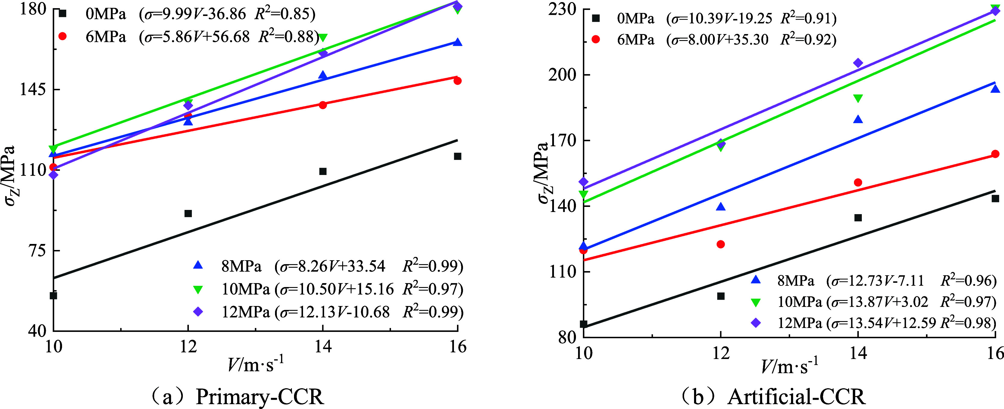
Relationship between impact velocity and peak stress of coal rock combination.
As depicted in Figure 6, under constant hydrostatic pressure, the combined strength of both types of rock samples increases with higher strain rates, demonstrating a notable strain rate effect and adhering to an exponential function fitting relationship (R2 ≥ 0.85). Comparative analysis reveals variations in sample combination strength under different hydrostatic pressures, significantly influenced by the type of sample combination. For instance, at a hydrostatic pressure of 6 MPa, the variation trend in the combined samples of both types is similar. The minimum and maximum combined strengths of primary-CCR are 111.21 and 148.72 MPa, respectively, representing 92.73 and 90.77% of the corresponding extreme values of artificial-CCR. Thus, the strength of primary-CCR is significantly lower than that of artificial-CCR. Furthermore, comparing the variation range of composite rock samples under varying hydrostatic pressure, it is evident that as hydrostatic pressure increases, the disparity between the maximum and minimum values of the two sample types becomes increasingly significant, indicating differing impacts of varying hydrostatic pressure on the sensitivity of composite rock samples to combination strength.
The relationship between the combined strength of two types of coal and rock and hydrostatic pressure is illustrated in Figure 7. As depicted in Figure 7, hydrostatic pressure has two effects on combined strength: “low pressure strengthening” and “high pressure weakening.” When the impact velocity remains constant, the combined strength of primary-CCR increases with rising hydrostatic pressure, with an inflection point at 10 MPa. Prior to the inflection point, low hydrostatic pressure enhances combined strength, while after the inflection point, hydrostatic pressure weakens it. The combined strength of artificial-CCR also increases with hydrostatic pressure, and the sensitivity of hydrostatic pressure decreases with increasing impact velocity. This may be due to the fact that the static load compressive strength is as follows: artificial-CCR > primary-CCR. artificial-CCR is affected by interface friction, making its strength relatively significant and less prone to deformation and damage under low static water pressure, while primary-CCR is the opposite.
Figure 7.
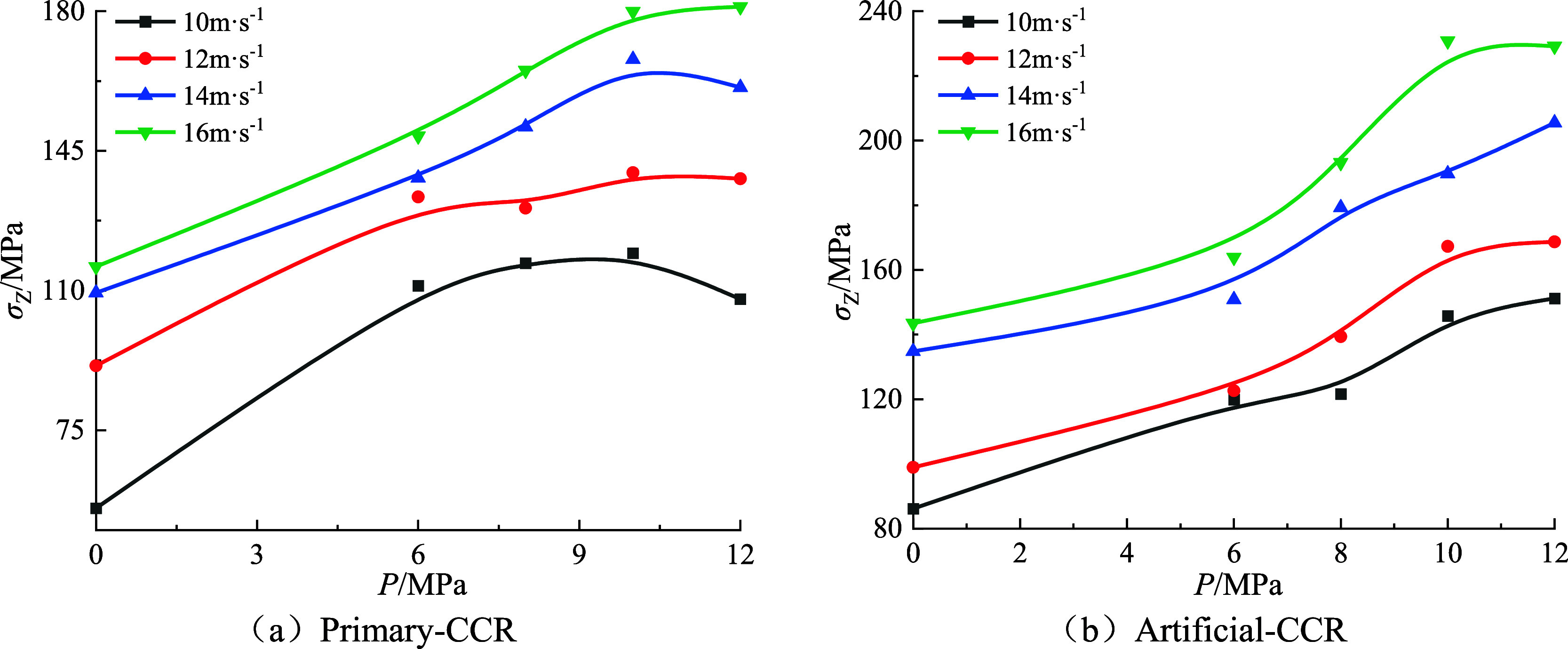
Relationship between hydrostatic pressure and sample combination strength.
3.1.2. Impact Toughness Characteristics
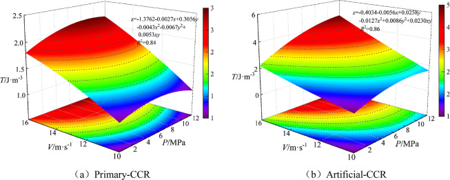
The ability of the two types of composite rocks to resist impact damage was characterized by defining the area of the stress–strain curve as the impact toughness of the specimen.43 Impact toughness T represents the comprehensive performance of the material, encompassing dynamic compressive strength and deformation ability, thus providing a more comprehensive representation of the material’s performance. Figure 8 illustrates the relationship curve of impact velocity, hydrostatic pressure, and impact toughness.
Figure 8.
Relationship between impact velocity and specimen impact toughness.
Figure 8 demonstrates that, under identical hydrostatic pressure, the impact toughness of both primary-CCR and artificial-CCR increases with the elevation of impact velocity, signifying a significant linear growth correlation. Specifically, the impact toughness of artificial-CCR escalates with increasing hydrostatic pressure. Importantly, the growth rate is faster in the range of 0–10 MPa compared to 10–16 MPa. The impact toughness and hydrostatic pressure of primary-CCR initially increased and then decreased, with the most substantial toughening effect observed at 10 MPa. Both data sets can be suitably fitted using the Ploy2D function in ORIGIN, yielding a fitting coefficient R2 ≥ 0.84. Furthermore, the trend in impact toughness aligns with the variation in rock composite strength. This suggests that the overall performance of artificial-CCR exceeds that of primary-CCR. Moreover, the impact load and hydrostatic pressure have a similar effect on toughness, in addition to enhancing the composite strength. Importantly, when using artificial-CCR instead of primary-CCR in laboratory experiments, the calculated compressive strength and impact toughness are relatively higher. This difference arises because impact toughness reflects the strength and deformation characteristics of the sample, while the strengthening/weakening effect of hydrostatic pressure acts to reinforce/weaken the composite rock sample by promoting the closure of internal cracks or facilitating the expansion and development of cracks. Therefore, hydrostatic pressure also exerts a low-pressure strengthening and high-pressure weakening effect on impact toughness.
3.2. Energy Dissipation Characteristics
3.2.1. Energy Stage Evolution Characteristics
The fundamental nature of macroscopic failure induced in the sample under an impact load involves energy absorption and release. When the stress wave is transmitted to the end face of the sample, according to elastic wave theory, the impedance of the end face does not match, leading to the reflection/transmission of a portion of the stress wave, subsequently causing damage to the sample. This process encompasses the breeding, expansion, and penetration of specimen cracks, accompanied by energy absorption and dissipation. The energy consumption during crushing can represent the failure process of the rock sample. To characterize the energy evolution characteristics of composite rock samples, in conjunction with typical compressive strength-strain curves, the impact failure response curves of composite rock samples are categorized into different stages based on dissipated energy. Subsequently, the differences in energy evolution between primary and artificial composite rock samples are compared, as depicted in Figures 9 and 10.
Figure 9.
Dynamic compressive strength-strain energy evolution curve of primary-CCR.
Figure 10.
Dynamic compressive strength-strain energy evolution curve of artificial-CCR.
It is evident from Figures 9 and 10 that under impact loading, the absorbed energy of both types of composite rock samples increases with strain and eventually stabilizes. The dissipated energy exhibits a typical linear stage characteristic with the increase of strain, as follows:
In the OA stage, denoting the elastic energy storage phase, point A marks the transition point (yield point) of the stress–strain curve, signifying the shift from a linear to a nonlinear slope. According to the energy balance theory, the slope of the absorbed energy curve at this stage is minimal, resulting in a slow increase in crushing energy. This stage involves the storage of external load energy in the form of elastic deformation energy within the sample without inducing damage.
In the AC stage, representing the plastic energy storage phase encompassing prepeak plastic yield energy storage and postpeak plastic softening energy storage, notable distinctions exist between the two types of combined coal rocks. Notably, for the primary-CCR stress–strain curve at P = 6–10 MPa, a plastic plateau is evident in the plastic stage. Moreover, the overall stress in this stage initially increases and then decreases with the increase in strain. However, at a strain increase of 0.007, the dynamic compressive strength only changes by 13.91 MPa. The plastic energy storage stage of artificial-CCR comprises both prepeak plastic yield energy storage and postpeak plastic softening energy storage, indicating the significant nonlinear characteristics of the prepeak and postpeak stages of artificial-CCR.
Taking Figures 9b and 10b as an example, B represents the peak point of the stress–strain curve, with a peak stress of 148.34 MPa. The AB stage corresponds to the prepeak plastic yield storage stage, where cracks in the samples are generated and expanded over a large area, dissipating energy due to internal damage in the composite samples, while elastic energy continues to accumulate. The BC stage represents the postpeak plastic softening energy storage, with C marking the peak point of the dissipative energy curve. At this stage, internal cracks continue to develop, destroying the original load-bearing structure of the sample rock, leading to a rapid increase in energy dissipation. However, due to the lag of energy transfer relative to the crack propagation speed, the crushing energy cannot fully act on crack propagation and penetration, preventing overall instability failure, and keeping the elastic energy in the accumulation stage.
For example, in Figures 9b and 10b, point B represents the peak of the stress–strain curve, with a peak stress of 136.34 MPa. In the AB stage, during the prepeak plastic yield energy storage phase, internal cracks within the sample initiate and propagate extensively, resulting in energy dissipation due to the internal damage of the composite rock sample. However, elastic energy continues to accumulate at this stage.
In the BC stage, representing the postpeak plastic softening energy storage phase, the dissipative energy curve at point C exhibits a slow slope. During this stage, cracks in the specimen persist in developing, leading to the destruction of the original load-bearing structure of the sample and consequently causing a rapid increase in energy dissipation. However, due to the lag in energy transfer relative to the speed of crack propagation, the crushing energy fails to fully impact crack propagation and penetration, preventing overall instability failure of the sample and allowing elastic energy to continue accumulating.
CD stage: This is the failure exergy stage, with D representing the stress residual point at the end of the impact experiment. The stress at this stage decreases sharply with the increase of strain, and the slope of the stress–strain curve drops sharply compared to the plastic energy storage stage. The dissipative energy accumulates to the limit of energy storage, and the energy evolution stabilizes. At this stage, primary and secondary cracks rapidly expand and penetrate inside the sample, and the elastic strain energy reaches its limit, leading to the release or transfer of elastic energy to the adjacent rock mass in the form of kinetic energy of broken coal rock fragments, resulting in the overall instability and failure of the sample.
3.2.2. Dissipated Energy Density Characteristics
The fragmentation dissipation reflects the energy dissipation characteristics of composite rocks, and the variation law of the dissipation energy of composite rock samples with incident energy under dynamic and static loading is shown in Figure 11.
Figure 11.
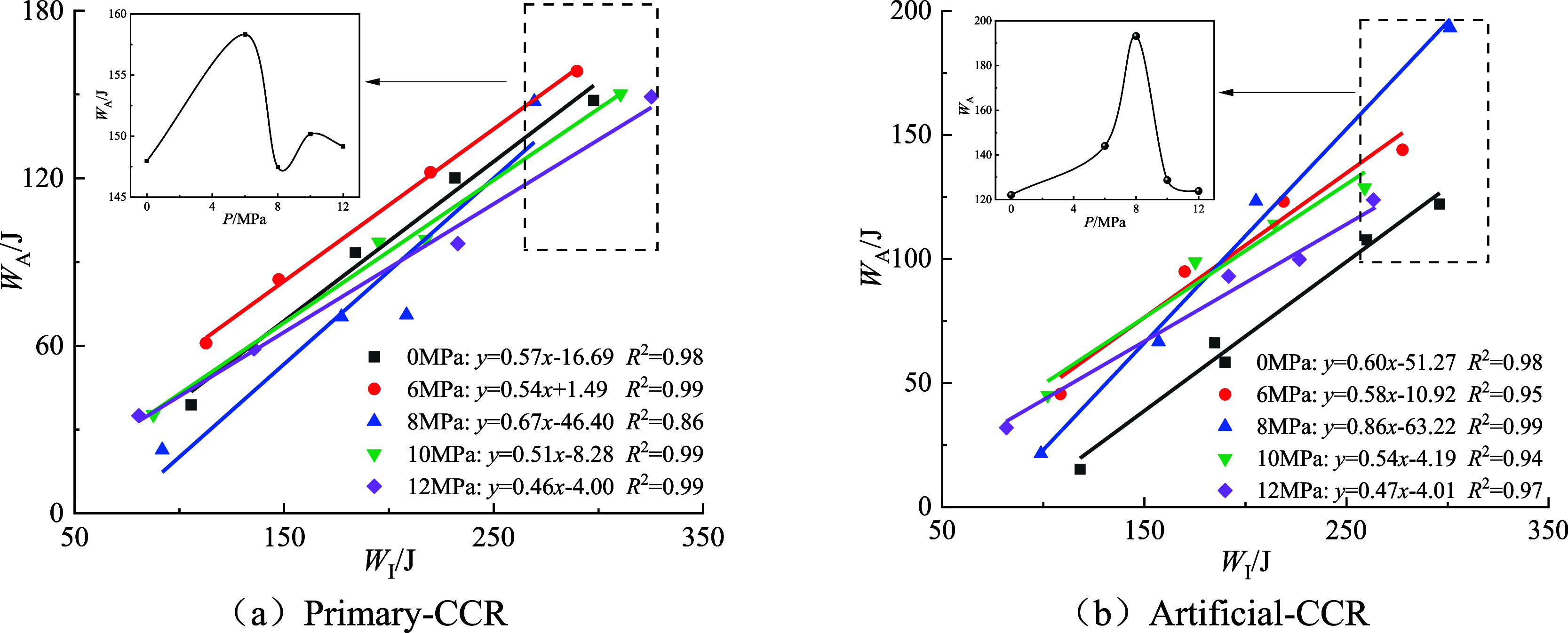
Relationship between incident energy and dissipated energy of composite coal and rock.
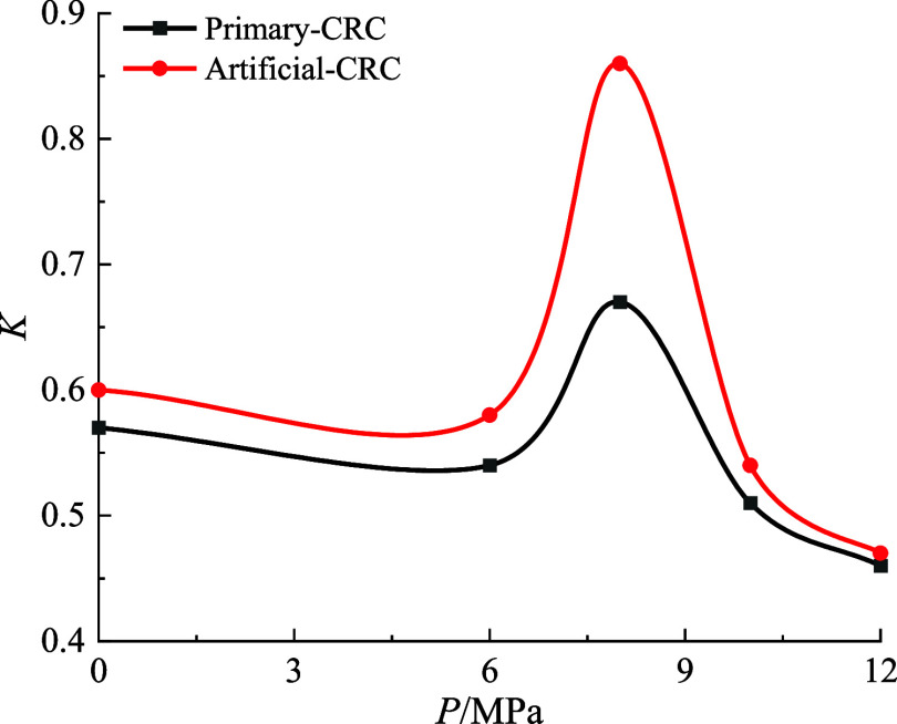
It is evident from Figure 11 that the dissipated energy density of the two types of composite rock samples under varying hydrostatic pressure follows a linear trend with the incident energy, increasing as the incident energy rises. A comparison of the two composite rock samples reveals that at 0 MPa hydrostatic pressure, as the impact velocity escalates from 10 to 16 m/s, the dissipated energy density of primary-CCR increases from 0.39 to 1.47 J/cm3, marking a 276% rise. In contrast, the dissipated energy density of artificial-CCR surged from 0.15 to 1.21 J/cm3, reflecting a 706% increase, resulting in a difference of 2.56 times. At 8 MPa hydrostatic pressure, with the impact velocity increasing from 10 m/s to 16 m/s, the dissipated energy density of primary-CCR rose from 0.23 to 1.47 J/cm3, representing a 539% increase. Similarly, the dissipated energy density of artificial-CCR grew from 0.21 to 1.92 J/cm3, indicating an 814% increase, with a difference of 1.51 times, demonstrating the relatively high dissipated energy density of artificial-CCR. The discrepancy may be attributed to a weak layer at the interface of primary-CCR, leading to lower strength compared to artificial-CCR, thereby making the sample prone to overall instability failure and resulting in a slower growth of dissipated energy density. In contrast, the interface of artificial-CCR consists of epoxy resin cement, which exhibits a certain level of cohesiveness. Simultaneously, the coal and rock components are prepared from the intact sample, which exhibits fewer macroscopic cracks and relatively high deformation resistance energy. To assess and differentiate the dissipated energy density between the two types of composite rocks, the relationship between slope K, hydrostatic pressure, and sample type is depicted based on the curve fitting results in Figure 11, as illustrated in Figure 12.
Figure 12.
Relationship between slope K and static water pressure and sample type.
It is evident from Figure 12 that the growth rate of dissipated energy in combined coal and rock initially increases and then decreases with rising hydrostatic water pressure, indicating a dual effect of hydrostatic water pressure on energy absorption. This phenomenon may be attributed to the compaction of internal pores in the combined coal, particularly within the coal, and the resulting reduction in wave impedance mismatch under static water pressure. Consequently, the combined coal must overcome slip and friction effects caused by initial pores, cracks, and other defects when subjected to external impact loads, leading to a significant increase in the growth rate of dissipative energy. However, excessive initial hydrostatic load can result in rock deformation and failure. At a relative hydrostatic pressure of 0 MPa, the initiation and expansion of microcracks decrease, leading to a reduction in the energy to be dissipated and, consequently, the growth rate of dissipative energy in the sample. Under low hydrostatic pressure conditions, as the pressure increases, the sample becomes compacted, reducing wave impedance mismatch and resulting in the dominant strengthening effect of hydrostatic pressure on energy dissipation, leading to an increase in the growth rate of dissipative energy in combined coal and rock. Conversely, under high hydrostatic pressure, the effect of hydrostatic pressure on sample deformation and failure is gradually enhanced, causing a continuous decrease in the growth rate of dissipative energy in the sample.
3.2.3. Characteristics of Specific Surface Energy
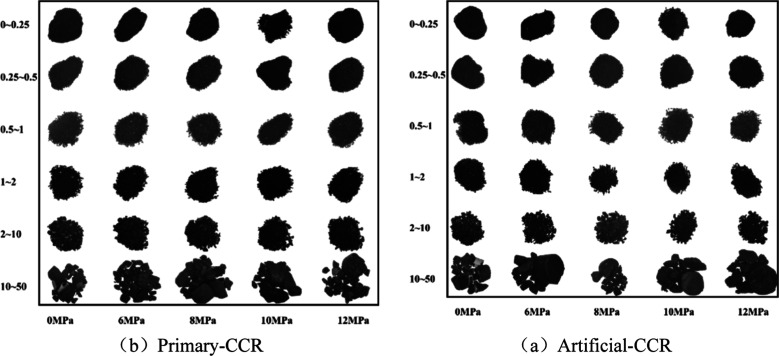
To quantify the impact of impact load, hydrostatic pressure, and sample type on the energy dissipation of coal and rock, the degree of energy dissipation and the ability to cause destruction per unit area are investigated. First, the crushed samples were sieved using standard mesh sizes of 0–0.25, 0.25–0.5, 0.5–1.0, 1.0–2.0, and 2.0–10.0 mm. Second, the particles in each size range were weighed, and their weights were recorded, as shown in the typical diagram of sample sieving in Figure 13. Then, the particles in each size range were transformed into spheres of corresponding average sizes, with i values of 1, 2, 3, 4, 5, 6. Finally, eq 5 calculates the number of equivalent spheres ni in the corresponding size range.
| 5 |
where: ri is the equivalent sphere diameter of the i particle range.
Figure 13.
Typical sample sieving diagram.
Sw reflects the new surface area of the sample after crushing compared with that before crushing, which can directly characterize the degree of breakage of the sample.44 In eq 6, the first term is the surface area of all fragments, and the sum of the second and third terms is the surface area of the original sample.
| 6 |
in order to accurately characterize the energy consumption capacity of the sample, compared with the dissipative energy density, the introduction of λw can accurately characterize the energy dissipation energy of the sample per unit surface area
| 7 |
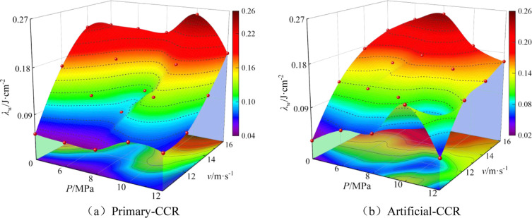
Figure 14 shows the surface variation of λw with P and v. It is evident from Figure 14 that the increase in impact load leads to an increasing trend in λw for the primary/artificial-CCR. When P = 12 MPa, and v increases from 10 to 12 m/s, the change in λw of the primary-CCR is only 0.0069 J·cm–3. This minor change may be attributed to the damage of the sample’s internal structure caused by the preadded high hydrostatic pressure, resulting in the low impact velocity’s inability to significantly affect the λw of the sample. In Figure 14a, with the increase of P, the λw of the artificial-CCR first increases and then decreases under different impact loads. As v increases from 10 to 16m/s, the inflection point moves forward from 10 to 8 MPa. The dual effect of hydrostatic pressure shows that low hydrostatic water pressure strengthens coal and rock, enhancing their compactness and deformation resistance. Consequently, the Sw of the sample is relatively reduced, leading to an initial increase and then decrease in λw with the increase of P. Simultaneously, at low impact loads, the energy only causes damage to easily expandable crack areas. When the impact load is large enough, the strengthening effect of hydrostatic pressure can be overcome to some extent, resulting in the advance of the curve’s inflection point. In Figure 14b, with the increase of P, λw of the artificial-CCR under different impact loads increases first and then decreases, with the curve’s inflection point close to 10 MPa. The impact load has no effect on the inflection point of the curve due to the premature fracture of the sample under the impact load, caused by the primary porosity, through fissures and interfaces in the primary-CCR.
Figure 14.
Surface variation of fragment area with static water pressure and impact velocity.
3.3. Macroscopic Crack Evolution Characteristics
3.3.1. Fractal Box Dimension Principle
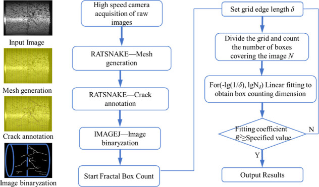
Surface cracks of brittle materials such as rocks exhibit significant fractal characteristics, and the size and distribution of macroscopic cracks can be quantitatively studied using the fractal dimension.45 The fractal box dimension is widely utilized and can fulfill the requirements for rock crack propagation calculation under impact load. The principle of the fractal box dimension involves dividing cracks in the sample using an equivalent grid with a side length δ, then calculating the nonempty grid subset F containing cracked pixels, and finally determining the fractal dimension of the combined rock sample under different impact loads. The specific procedure is illustrated in Figure 15. The box side length δ significantly impacts the number of nonempty boxes containing cracked pixels Nδ(F), which subsequently affects the fractal dimension D
| 8 |
in order to ensure the accuracy of the calculation results, it is necessary to preprocess the high-speed image results before calculating the fractal dimension to eliminate the interference such as shadow, noise and spots. As can be seen from Figure 15, RATSNAKE annotation software was used to extract cracks in the experiment, and the annotation results were imported into ImageJ software for fractal box dimension analysis to quantitatively describe the evolution characteristics of surface cracks during the whole process of the sample under impact load.
Figure 15.
Fractal box dimension calculation process.
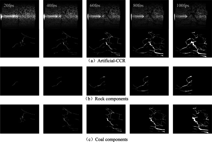
Image preprocessing is the premise of calculating crack fractal dimension. According to Figure 15, the original cracks and image binarization processing results of typical artificial-CCR (V = 14 m/s) were obtained, as shown in Figure 16.
Figure 16.
Original cracks and binarization results of composite samples Figure 16 indicates that, at an impact velocity of 14 m/s, the crack evolution of the coal and rock components of the artificial-CCR is significantly different, with the coal component exhibiting earlier crack generation than the rock component, consistent with the results of the number and length of cracks. At frame number 20, there are three main cracks on the surface of the coal component, while only one crack with a length of 10.61 mm is present on the surface of the rock component. At frame number 60, three main cracks ranging from 7.91 to 21.83 mm in length are present on the surface of the rock component. On the other hand, six cracks ranging from 7.29 to 27.25 mm in length are present on the surface of the coal component, with the number of cracks being more than twice that of the rock component, and the average crack length being 1.28 times that of the rock component. At frame number 100, four main cracks ranging from 8.65 to 25.99 mm in length are present on the surface of the rock component, while 11 cracks ranging from 6.85 to 28.75 mm in length are present on the surface of the coal component, with the number of cracks being 2.75 times that of the rock component, and the average crack length being 0.86 times that of the rock component. The significant difference in the static load compressive strength of the rock and coal components, with values of 104.00 and 12.50 MPa, respectively (rock > coal), may be the reason for the uncoordinated deformation of the two components. During the initial stage of impact loading, the coal component undergoes serious deformation and destruction under the influence of strength, resulting in a significantly higher macro-crack length and number of the coal than that of the rock component. As the impact loading continues, the crack propagates through to the rock component, mainly for the formation of macroscopic main cracks, resulting in relatively long main cracks with fewer numbers in the rock component. The structural characteristics of the coal and rock components reveal that the internal cracks, pores, and other primary defects of the coal are far more than those of the rock components, leading to stress concentration in the coal components, making it easier to absorb energy and reach the limit of energy accumulation.
3.3.2. Fractal Dimension Features
In order to explore the difference in crack growth of composite rocks, the sample 25 mm was taken as the central dividing line, and the fractal dimension of composite rocks, coal, rock components was obtained according to the principle of box dimension in combination with binarization images.46 The fractal dimension calculation results are shown in Figures 17 and 18.
Figure 17.
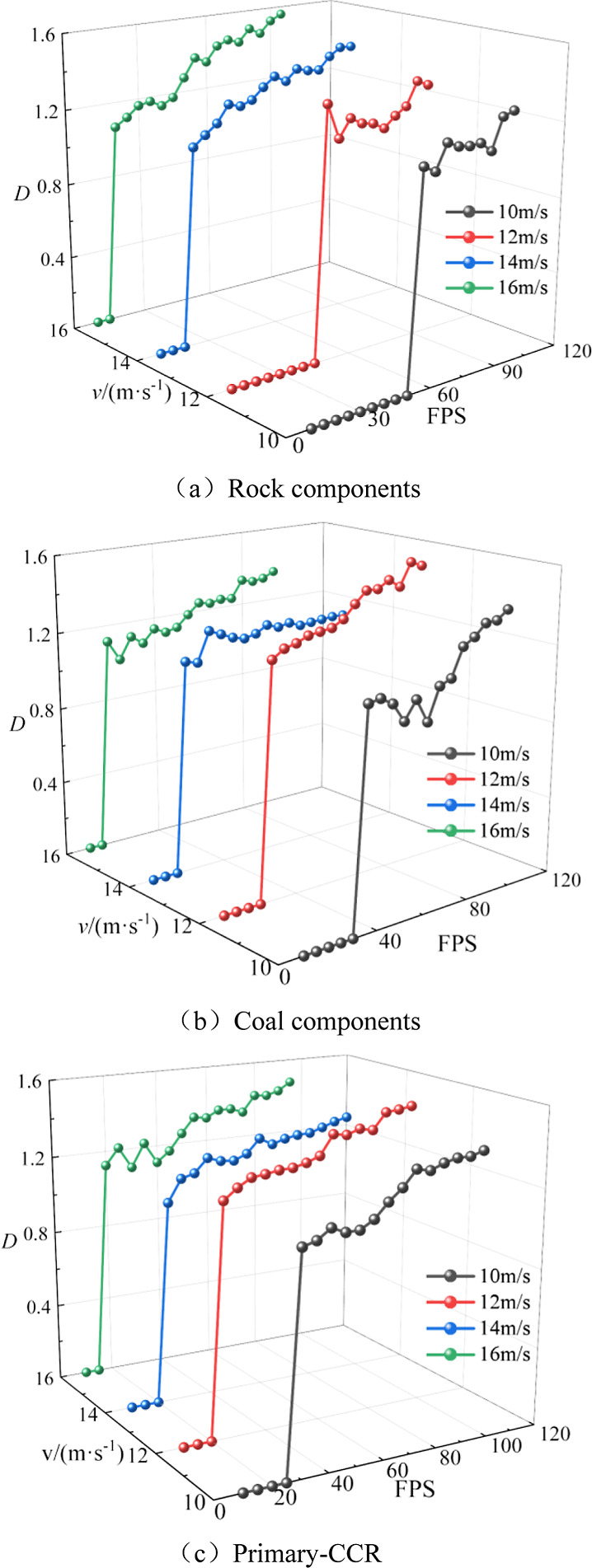
Fractal dimension of primary-CCR.
Figure 18.
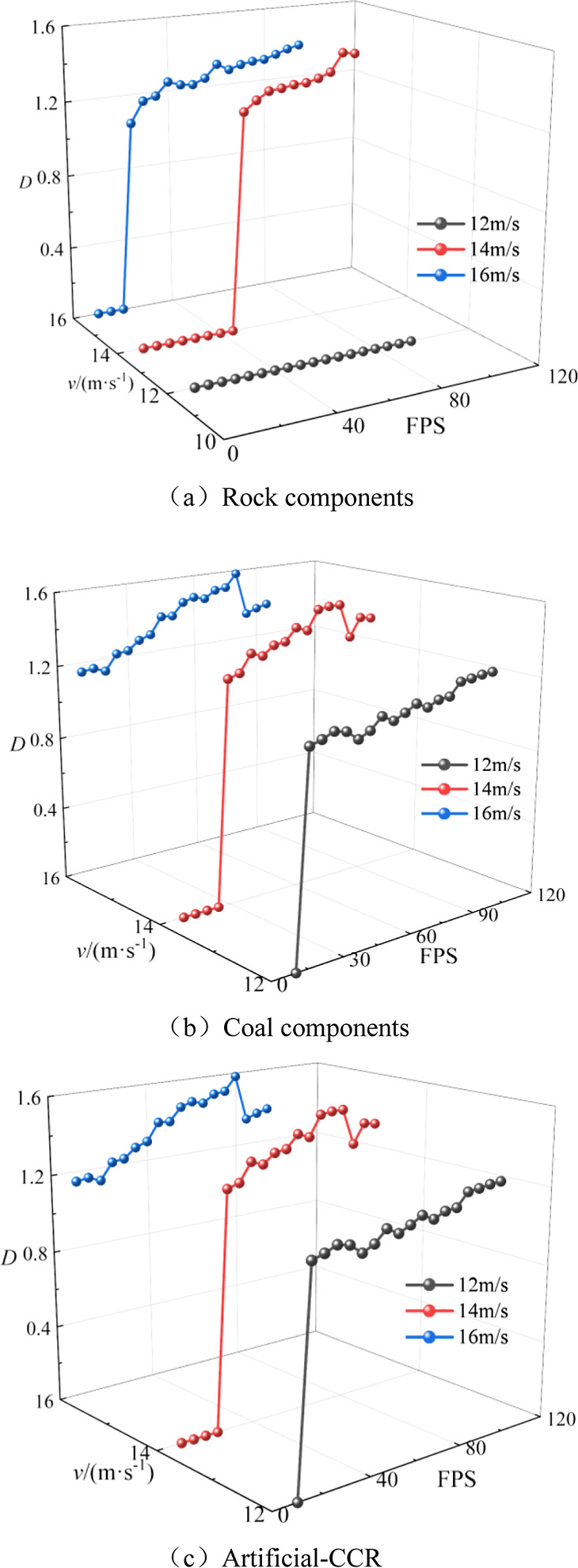
Fractal dimension of primary-CCR.
Figures 17 and 18 depict the characteristics of cracks in the combined primary/artificial rock, as well as the coal and rock components, exhibiting a degree of self-similarity. At varying impact velocities, these characteristics are characterized by stages as the frame number increases, including rapid increase, slow increase, and stable shock stages. Initially, macroscopic crack initiation leads to a rapid increase in fractal dimension. Subsequently, as the frame number increases (due to stress wave propagation), cracks transition from the initiation and development stage to the expansion and penetration stage, with a slower growth rate in fractal dimension. At the final impact load, the entire sample becomes unstable, maintaining the fractal dimension at a certain value, yet exhibiting relative shock. This behavior can be attributed to the internal complexity and heterogeneity of the specimen, as well as the dynamic evolution of crack propagation and closure. The growth rate of fractal dimension follows this order: Rock components < Coal components, artificial-CCR < primary-CCR, primarily due to the difference in strength and structure between coal and rock, with the primary-CCR exhibiting a notably higher growth rate. The energy transfer resulting from the heterogeneous interface accelerates the crack evolution process in artificial-CCR. At an impact velocity of 12 m/s, the fractal dimension indicates that at the current impact strength, only the coal component is destabilized, and the rock component solely serves as the energy transfer carrier for the composite rock sample, resulting in no significant macro damage. As the impact velocity increases, the overall fractal dimension increases, correlating with the growing complexity of the crack propagation path and the number of nonempty boxes containing crack pixels in binary image processing.
3.3.3. Analysis of Crack Evolution Mechanism
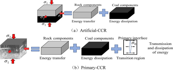
Based on the results of high-speed photography and fractal dimension, the combined rock sample is divided into three regions: energy transfer region, energy dissipation region, and energy transition concentration region, as shown in Figure 19.
Figure 19.
Energy action mechanism of composite rocks.
As shown in Figures 17 and 18 when the impact velocity is less than 14 m/s, the rock components in the artificial-CCR can crack and expand, resulting in a fractal dimension of 0. This may be attributed to the impedance matching effect between rock components and the incident rod, leading to a substantial reduction in the reflection of stress waves in rock components compared to coal components. Consequently, rock components play a greater role in energy accumulation and transfer under stress wave action. When the impact velocity is ≥14 m/s, the rock components are affected by the impact load, resulting in secondary cracks, crack propagation, and penetration, leading to the transition of rock components from energy transfer to dissipation. Taking primary-CCR as an example, when the impact velocity is 10–16 m/s, crack initiation, propagation, and penetration can occur in each component of primary-CCR, with the fractal dimension of each component being greater than 0. This may be due to a significant distinction between the primary interface and the artificial interface, with numerous defects, including primary cracks and joints, present in the region. Energy accumulation, transfer, and dissipation can occur at the interface through crack expansion, penetration, and compaction, thereby lowering the energy threshold for the overall destabilization failure of primary-CCR. Rock components serve as energy transfer and dissipation zones. In summary, the rock components in artificial-CCR transition from energy transfer to dissipation only when the impact velocity is ≥14 m/s, while the rock components in primary-CCR can both transfer and dissipate energy. An energy threshold at the primary interface mitigates the assembly’s instability and facilitates energy transfer and dissipation. The strength disparity between the two composite rock sample types primarily stems from the energy action mode at the interface.
3.4. Microscopic Cross-Sectional Morphology Characteristics
3.4.1. SEM Microscopic Morphology
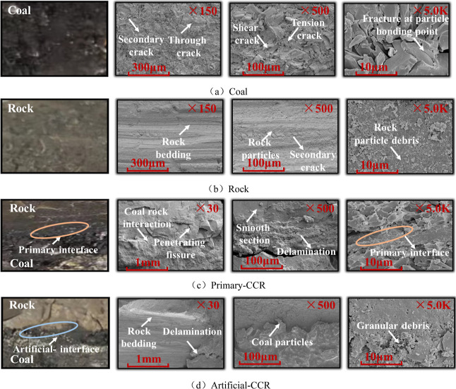
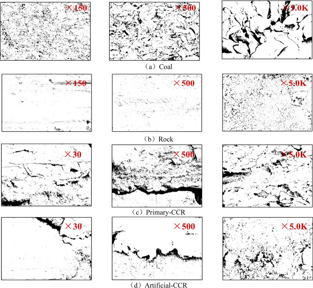
To characterize the cross-sectional microscopic features and surface mineral structure of the composite rock,47−49 a SU8020 scanning electron microscope with a resolution of 50 nm was employed. The experimental procedure involved sample preparation, gold spraying, system focusing, image signal generation, and sample extraction. SEM tests were conducted on rock, coal, primary-CCR, and artificial-CCR samples, each measuring 10 mm × 10 mm × 10 mm. The microsurface and micromorphological characteristics of these four typical samples are presented in Figure 20.
Figure 20.
SEM of the cross-section of composite rocks.
From Figure 20a, it is evident that due to their metamorphic nature, coals tend to exhibit stratification after failure, with disorderly development of joints and cracks. At high external impact energy levels, debris adheres to particle surfaces, leading to significant fragmentation of coal components due to the combined action of external load and internal forces within the sample. The energy carried by the external load, coupled with pre-existing damage within the sample and initial weak surfaces, results in coal components being able to absorb energy only through their own deformation and failure. Examination of Figure 20b reveals that the rock group comprises sedimentary rock, with relatively few internal cracks initiated and developed under external loads. This indicates a dense and stable internal structure of the rock component, with relatively few microdefects such as macro-joints and cracks. Under equivalent energy impact, the rock component primarily serves as an energy transfer medium, absorbing energy through elastic deformation and transferring it to the coal component. Figure 20c illustrates the presence of an interlayer area between coal and rock media in primary-CCR, where cracks and weak surfaces traverse through the coal and rock layers. Following Griffith theory, the strength of rock components in the crack area at the interface is diminished, leading to uneven stress distribution and concentration of stress in the crack area. Examination of Figure 20d reveals substantial differences between the artificial-CCR interface and the primary-CCR interface, particularly in the development of fractures at the interface, leading to marked differences in the failure modes of the two types of combined rocks under equivalent energy impact, such as at an impact velocity of 14 m/s. This is due to the fact that the energy at the interface of artificial-CCR is predominantly transferred through rock components, and stress distribution is challenging to alter at the interface due to the absence of cracks through the specimen’s interface. Consequently, artificial-CCR is less prone to fracture or destruction.
3.4.2. Section Roughness Characteristics
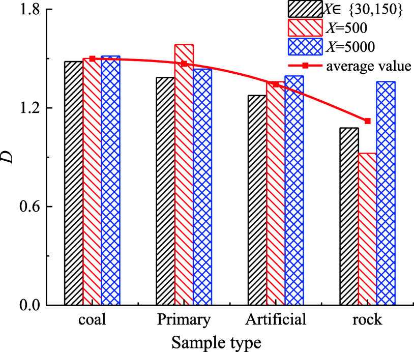
In order to further investigate the impact damage characteristics of the primary and artificial interfaces and establish the correlation between macro-failure characteristics and the coal-rock structure, we utilized the fractal dimension to quantitatively characterize the roughness of the coal-rock and interface section. Initially, the SEM image was converted into a grayscale image with a scale of 8 using IMAGEJ software, following which the binary image was divided based on the selected equivalent mesh side length. Subsequently, employing the calculation principle of fractal dimension, we determined the proportion of covered grids and then computed the fractal dimension.50,51Figure 21 displays the gray levels of coal and rock monomers, primary interface, and artificial interface, while the relationship between the fractal dimension and sample type is illustrated in Figure 22.
Figure 21.
Binary SEM image of coal rock cross-section.
Figure 22.
Relationship between fractal dimension and sample type.
Upon reviewing Figures 21 and 22, a significant correlation between sample type and section roughness at different magnification levels becomes apparent. Notably, the section roughness follows the order of coal > primary interface > artificial interface > rock, aligning with the SEM image results. When subjected to impact load at the coal-primary interface, the sample’s resistance to deformation is relatively low due to the influence of primary pore structure, cracks, and bedding within the sample, rendering it more susceptible to fracture. Consequently, the fracture surface exhibits increased complexity. In contrast, the artificial interface, characterized by a relatively homogeneous rock composition and high structural strength, presents greater resistance to fracture under impact load, resulting in a relatively simpler fracture surface. This observation aligns with the crack propagation pattern in combined primary and artificial-CCR, offering a microcosmic explanation for the evolution of crack paths. Furthermore, due to the limited experimental conditions related to coal-rock impact failure, the study did not account for factors such as gas pressure, the roughness of the primary coal–rock interface, and the inclination angle. Future research should aim to improve the SHPB system to enable fluid-structure coupling. Additionally, the primary combined coal–rock mass can be reconstructed using a CT scanning system to facilitate relevant numerical simulation studies.
4. Conclusions
-
(1)
The compressive strength of composite coal rock has a significant linear relationship with impact velocity. The compressive strength of primary-CCR increases initially and then decreases with increasing pressure, while the compressive strength of artificial-CCR increases with pressure. The toughness of both types of composite rock samples increases with impact velocity, with the toughest effect observed in primary-CCR at a hydrostatic pressure of 10 MPa.
-
(2)
The evolution of energy in composite coal rock under impact load includes elastic energy storage, plastic energy storage, and destructive energy discharge stages. The energy dissipation of both types of composite coal rock increases with impact velocity, showing a significant linear function relationship, with the growth rate being greater in artificial-CCR than in primary-CCR. The λW parameter of primary/artificial combined coal increases initially and then decreases with pressure. As impact load increases, the inflection point of λW for artificial combined coal shifts forward.
-
(3)
The crack growth of composite coal follows a fractal pattern, with the fractal dimension increasing with impact velocity. Under the same impact conditions, the crack propagation degree and number of primary-CCR are higher than those of artificial-CCR. Additionally, through SEM image analysis, it is observed that the coal-rock type significantly affects the section roughness.
-
(4)
The rock components in composite coal rock play a role in energy accumulation and transfer. When the impact velocity is ≥14 m/s, the rock components in artificial-CCR transition from energy transfer to energy dissipation. The interface of primary-CCR can serve as both energy transfer and dissipation, making it prone to global instability. Most of the energy of artificial-CCR is used to break through the interface boundary, and the energy threshold required for failure is higher than that of primary-CCR.
Acknowledgments
This study was financially supported by Foundation of Anhui Engineering Laboratory of Explosive Materials and Technology(AHBP2022A-03), Guizhou Provincial Program on Commercialization of Scientific and Technological Achievements[2023]general 108, Fundamental Research Funds for the Central Universities (2023ZKPYAQ04) .
The authors declare no competing financial interest.
References
- Beijing X.; Zheng L.; Chen D. X.; Zhong S. Q. Dynamic characteristics and constitutive model of coal samples with different length diameter ratio. J. Min. Sci. Technol. 2023, 8 (2), 190–201. 10.19606/j.cnki.jmst.2023.02.006. [DOI] [Google Scholar]
- Chen S.; Li F. X.; Yin D. W.; Zhang J. C. Experimental study on deformation failure characteristics of limestone-coal composite with different rock-coal height ratios. J. Cent. South Univ. 2023, 54 (6), 2459–2472. 10.11817/j.issn.1672-7207.2023.06.032. [DOI] [Google Scholar]
- Jun Z.; Zhao G. M.; Meng X. R.; Wu X. K.; Zhang Q. H.; Qi M. J. Dynamic impact energy dissipation characteristics of granite with different height-diameter ratios. J. Min. Saf. Eng. 2023, 40 (2), 379–386. 10.13545/j.cnki.jmse.2022.0060. [DOI] [Google Scholar]
- Xiangzhuo Z.; Wang C. G.; Zhou K. Y.; Guo L.; Zhang J.; Li Y. P.; Zhang W.; Sun J. Q. Geo-dynamic conditions instability and support optimization of semi coal-rock roadway in large inclined and extra thick coal seam. Coal Sci. Technol. 2022, 50 (11), 20–29. 10.13199/j.cnki.cst.2021-0200. [DOI] [Google Scholar]
- Lu Y. Y.; Peng Z. Y.; Xia B. W.; Yu P.; Ou C. N. Coal and gas outburst multi-functional physical model testing system of deep coal petrography engineering. J. China Coal Soc. 2020, 45 (S1), 272–283. 10.13225/j.cnki.jccs.2019.1433. [DOI] [Google Scholar]
- Li G. S.; Li Z. H.; Du F.; Wang W. Q.; Xu J. Study on effect of gangue thickness on stability of coal wall of working face gangue-bearing coal seam. China Safety Sci. J. 2023, 33 (10), 183–191. [Google Scholar]
- Zhao H. B.; Ji D. L.; Liu S. Q.; Cheng H.; Wu T. Study on dynamic response and constitutive model of composite rock under impact loading. Chin. J. Rock Mech. Eng. 2023, 42 (01), 88–99. 10.13722/j.cnki.jrme.2022.0523. [DOI] [Google Scholar]
- Liu S. H. Nonlinear catastrophy model and chaotic dynamic mechanism of compound coal-rock unstable failure under coupled static-dynamic loading. J. China Coal Soc. 2014, 39 (02), 292–300. 10.13225/j.cnki.jccs.2013.2007. [DOI] [Google Scholar]
- Zhou Y.; Zou S. Z.; Gao Y. T.; Guo W. H.; Wu X. L. Test and numerical simulation for mechanical properties of laminated rock mass under dynamic loading. J. Harbin Inst. Technol. 2023, 55 (06), 93–109. 10.11918/202207020. [DOI] [Google Scholar]
- Wen S.; Zhao X. W.; Chang Y. L.; Li B. Energy Dissipation of Dynamic Failure of Mixed Rock Specimens Subject to SHPB Compression. J. Basic Sci. Eng. 2021, 29 (2), 483–492. 10.16058/j.issn.1005-0930.2021.02.020. [DOI] [Google Scholar]
- Kang Y. M.; Gu J.; Wei M. Q. Mechanical properties of soft and hard interbedded rock under impact load. J. Cent. South Univ. 2023, 54 (3), 1062–1073. 10.11817/j.issn.1672-7207.2023.03.023. [DOI] [Google Scholar]
- Wang Y. B.; Ren B.; Geng Y. J.; Li Z. K. A study on impact dynamic characteristics of soft and hard medium combined rock mass. J. Vib. Shock 2023, 42 (12), 135–144. 10.13465/j.cnki.jvs.2023.012.015. [DOI] [Google Scholar]
- Zuo J. P.; Chen Y.; Cui F. Investigation on mechanical properties and rock burst tendency of different coal-rock combined bodies. J. China Univ. Min. Technol. 2018, 47 (1), 81–87. 10.13247/j.cnki.jcumt.000795. [DOI] [Google Scholar]
- Zheng J. W.; Wang S. W.; Li H. T.; Yang G. Q.; Lv D. Z.; Liu B.; Fu Y. K.; Li X. P.; Lei G. R. Experimental study on compressive strength characteristics of coal-rock combinations influenced by number of bedding surfaces. Coal Geol. Explor. 2023, 51 (5), 11–22. 10.12363/issn.1001-1986.22.10.0787. [DOI] [Google Scholar]
- Chen G. B.; Zhang J. W.; Li T.; Chen S. J.; Zhang G. H.; Lv P. F.; Teng P. C. Timeliness of damage and deterioration of mechanical properties of coal-rock combined body under water-rock interaction. J. China Coal Soc. 2021, 46 (S2), 701–712. 10.13225/j.cnki.jccs.2021.0995. [DOI] [Google Scholar]
- Cai Y. B.; Wang K.; Xu C. Comparative experimental study on deformation and damage characteristics of single coal rock and primary coal-rock combination. J. Min. Sci. Technol. 2020, 5 (3), 278–283. 10.19606/j.cnki.jmst.2020.03.005. [DOI] [Google Scholar]
- Wang K.; Fu Q.; Xu C.; Ai Z. B.; Li D.; Shu L. Y. The strength characteristics and competitive failure mechanism of primary coal-rock combination considering interface damage quantity. Fuel 2023, 352, 129057. 10.1016/j.fuel.2023.129057. [DOI] [Google Scholar]
- Gu X. B.; Guo W. Y.; Zhang C. H.; Zhang X. F.; Guo C. Q.; Wang C. Effect of interfacial angle on the mechanical behaviour and acoustic emission characteristics of coal-rock composite specimens. J. Mater. Res. Technol. 2022, 21, 1933–1943. 10.1016/j.jmrt.2022.09.104. [DOI] [Google Scholar]
- Yin D. W.; Chen S. J.; Ge Y.; Liu R. Mechanical properties of rock-coal bi-material samples with different lithologies under uniaxial loading. J. Mater. Res. Technol. 2021, 10, 322–338. 10.1016/j.jmrt.2020.12.010. [DOI] [Google Scholar]
- Li F. X.; Yin D. W.; Wang F.; Jiang N.; Li X. L. Effects of combination mode on mechanical properties of bi-material samples consisting of rock and coal. J. Mater. Res. Technol. 2022, 19, 2156–2170. 10.1016/j.jmrt.2022.05.174. [DOI] [Google Scholar]
- Zhang Y.; Yin L. D.; Dai L. P.; Zhang J. P.; Li J. J.; Yang C. C. Test and numerical study on impact failure of drilling coal samples under high strain rate. J. Vib. Shock 2024, 43 (9), 309–320. [Google Scholar]
- Gong F. Q.; Ye H.; Luo Y. The effect of high loading rate on the behaviour and mechanical properties of coal-rock combined body. Shock Vib. 2018, 2018, 1–9. 10.1155/2018/4374530. [DOI] [Google Scholar]
- Han Z. Y.; Li D. Y.; Li X. Dynamic mechanical properties and wave propagation of composite rock-mortar specimens based on SHPB tests. Int. J. Min. Sci. Technol. 2022, 32 (4), 793–806. 10.1016/j.ijmst.2022.05.008. [DOI] [Google Scholar]
- Yang R. S.; Li W. Y.; Fang S. Z.; Zhu Y.; Li Y. L. Experimental study on impact dynamic characteristics of layered composite rocks. Chin. J. Rock Mech. Eng. 2019, 38 (9), 1747–1757. 10.13722/j.cnki.jrme.2019.0021. [DOI] [Google Scholar]
- Xie B. J.; Yan Z. Dynamic mechanical constitutive model of combined coal-rock mass based on overlay model. J. China Coal Soc. 2019, 44 (02), 463–472. 10.13225/j.cnki.jccs.2018.1007. [DOI] [Google Scholar]
- Xie B. J.; Luan Z.; Liu T. L.; Wu B. W.; Zhong S. Q. Dynamic failure characteristics of primary coal-rock combination under hydrostatic pressure. J. China Coal Soc. 2023, 48 (5), 2153–2167. 10.13225/j.cnki.jccs.2023.0193. [DOI] [Google Scholar]
- Wen S.; Huang R. Z.; Zhang C. S.; Zhao X. W. Mechanical behavior and failure mechanism of composite layered rocks under dynamic tensile loading. Inter. J. Rock Mech. Min. Sci. 2023, 170, 105533. 10.1016/j.ijrmms.2023.105533. [DOI] [Google Scholar]
- Wang L.; Zhang S.; Liu H. Q.; Chen L. P.; Zhu C. Q.; Li S. B.; Wang A. C. Research on energy dissipation and damage failure law of gas-bearing coal under impact loading. Rock Soil Mech. 2023, 44 (07), 1901–1915. 10.16285/j.rsm.2023.0412. [DOI] [Google Scholar]
- Zhang H. M.; Chen S. G.; Wang L.; Cheng S. F.; Yang G. S.; Shen Y. J. Energy dissipation and fractal characteristics of weakly cemented red sandstone under disturbance impact. Chin. J. Geotech. Eng. 2022, 44 (04), 622–631. 10.11779/CJGE202204004. [DOI] [Google Scholar]
- Li C. J.; Xu Y.; Ye Z. Y. Energy dissipation and crushing characteristics of coal-rock-like combined body under impact loading. Chin. J. Geotech. Eng. 2020, 42 (05), 981–988. 10.11779/CJGE202005022. [DOI] [Google Scholar]
- Liu S. H. Nonlinear catastrophy model and chaotic dynamic mechanism of compound coal-rock unstable failure under coupled static-dynamic loading. J. China Coal Soc. 2014, 39 (02), 292–300. 10.13225/j.cnki.jccs.2013.2007. [DOI] [Google Scholar]
- Liu S. H.; Qin Z. H.; Lou J. F. Experimental study of dynamic failure characteristics of coal-rock compound under one-dimensional static and dynamic loads. Chin. J. Rock Mech. Eng. 2014, 33 (10), 2064–2075. 10.13722/j.cnki.jrme.2014.10.013. [DOI] [Google Scholar]
- Liu S. H.; Mao D. B.; Qi Q. X.; Li F. M. Under static loading stress wave propagation mechanism and energy dissipation in compound coal-rock. J. China Coal Soc. 2014, 39 (S1), 15–22. 10.13225/j.cnki.jccs.2013.0411. [DOI] [Google Scholar]
- Li X. L.; Zhao P. Z.; Duan Y. M.; Wang J. G.; Mu Y. Y. Study on energy transfer law of rock and filling body combination specimen. J. Saf. Environ. 2023, 23 (1), 101–106. 10.13637/j.issn.1009-6094.2021.1532. [DOI] [Google Scholar]
- Li C. Y.; Lei G. R.; He T.; Zuo J. P.; Yu X.; Zheng J. W.; Qi Q. X. Crack development characteristics and fracture modes of primary coal-rock mass induced by the unloading of confining pressure in deep coal mining. J. China Coal Soc. 2023, 48 (02), 678–692. [Google Scholar]
- Xia K. W.; Wang S.; Xu Y.; Chen R.; Wu B. B. Advances in experimental studies for deep rock dynamics. Chin. J. Rock Mech. Eng. 2021, 40 (03), 448–475. [Google Scholar]
- Xia K. W.; Xu Y.; Chen R. Dynamic tests of rocks subjected to simulated deep underground environments. Hazard Control Tunnelling Underground Eng. 2019, 1 (1), 58–75. [Google Scholar]
- Xu C.; Wang W. H.; Wang K.; Hu K.; Cao Z. G.; Zhang Y. Influence of coal-rock interface inclination on the damage and failure law of original coal-rock combination. Eng. Failure Anal. 2024, 161, 108275. 10.1016/j.engfailanal.2024.108275. [DOI] [Google Scholar]
- Li D. Y.; Han Z. Y.; Zhu Q. Q.; Zhang Y.; Ranjith P. G. Stress wave propagation and dynamic behavior of red sandstone with single bonded planar joint at various angles. Int. J. Rock Mech. Min. Sci. 2019, 117, 162–170. 10.1016/j.ijrmms.2019.03.011. [DOI] [Google Scholar]
- Xie B. J.; Yu R. X.; Chen D. X.; Luan Z.; Yang F. Study on influencing factors of energy consumption index of limestone under dynamic load. J. Saf. Sci. Technol. 2022, 18 (11), 62–70. [Google Scholar]
- Yang G. L.; Bi J. J.; Zhang Z. F.; Li X. G.; Liu J.; Hong P. X. The influence of the bedding angle under passive confining pressure on the dynamic strength and energy consumption of shale. J. Min. Sci. Technol. 2021, 6 (02), 188–195. 10.19606/j.cnki.jmst.2021.02.006. [DOI] [Google Scholar]
- Li D. Y.; Hu C. W.; Zhu Q. Q. Experimental study on mechanical properties and failure laws of granite with an artificial flaw under coupled static and dynamic loads. Chin. J. Rock Mech. Eng. 2020, 39 (06), 1081–1093. 10.13722/j.cnki.jrme.2019.1089. [DOI] [Google Scholar]
- Lin C. Y.; Wang Q. R.; Yang L. Y.; Wu Y. X.; Li Q. T.; Xie H. Z.; Wang Z. Y.; Zhang F. Mechanical Behavior and Constitutive Relationship of Basalt Fiber Reactive Powder Concrete Under Impact Loading. Mater. Rep. 2022, 36 (19), 103–109. 10.11896/cldb.21050237. [DOI] [Google Scholar]
- Li M.; Yu H.; Zhang J. Z.; Lin G.; Zhang L. Y.; Chen Y. L.; Zhu F. Q.; Mao Y. W.; Chen H.; Ding Z. B.; Liang Y. H. Study on dynamic mechanical response characteristics and fracture energy dissipation mechanism of sandstones with different saturations under real-time low temperature. Geomech. Geophys. Geo-Energy Geo-Resour. 2023, 9 (1), 77. 10.1007/s40948-023-00622-3. [DOI] [Google Scholar]
- Sun X. Y.; Jin T. X.; Li J. H.; Xie J. L.; Li C. T.; Li X. X. Dynamic characteristics and crack evolution laws of coal and rock under split Hopkinson pressure bar impact loading. Meas. Sci. Technol. 2023, 34 (7), 075601. 10.1088/1361-6501/acca3b. [DOI] [Google Scholar]
- Wang H.; Zong Q.; Wang H. B.; Wang L. X.; Xu Y.; Wang F. Fractal characteristics of fracture toughness and crack propagation of water saturated tuff under impact load. Chin. J. Rock Mech. Eng. 2023, 42 (07), 1709–1719. 10.13722/j.cnki.jrme.2022.0828. [DOI] [Google Scholar]
- Gao Y.; Yu Z. X.; Chen W. Q.; Yin Q.; Wu J. Y.; Wang W. Recognition of rock materials after high-temperature deterioration based on SEM images via deep learning. J. Mater. Res. Technol. 2023, 25, 273–284. 10.1016/j.jmrt.2023.05.271. [DOI] [Google Scholar]
- Huang L. Q.; Wang J.; Momeni A.; Wang S. F. Spalling fracture mechanism of granite subjected to dynamic tensile loading. Trans. Nonferrous Met. Soc. China 2021, 31 (7), 2116–2127. 10.1016/S1003-6326(21)65642-X. [DOI] [Google Scholar]
- Xie B. J.; Luan Z.; Li H.; Wu B. W.; Li X. X.; Chen D. X. Dynamic tensile mechanical properties of red sandstone under different pulse widths and amplitudes: Brazilian disk experiment and macroscopic and microscopic analysis. J. Mater. Res. Technol. 2024, 30, 5192–5218. 10.1016/j.jmrt.2024.04.168. [DOI] [Google Scholar]
- Yin T.; Lu J.; Yang Y.; Wu Y.; Wang J. H.; Men J. Q. Fracture behavior of yellow sandstone under freeze–thaw cycles with varied saturation states: An investigation of mode I fracture. Geomech. Energy Environ. 2023, 36, 100502. 10.1016/j.gete.2023.100502. [DOI] [Google Scholar]
- Jin Z. H.; Xie F. X.; Yang T. F.; Han X.; Chen X. D.; Zhang Y. Fractal dimension analysis of concrete specimens under different strain rates. J. Build. Eng. 2023, 76, 107044. 10.1016/j.jobe.2023.107044. [DOI] [Google Scholar]


