Abstract
Background
Hybrid surgery (HS) combined cervical disc arthroplasty (CDA) with anterior cervical discectomy and fusion (ACDF) is emerging, but its biomechanical effects as a revision surgery (RS) on adjacent segments were unclear.
Objectives
This finite element (FE) study aimed to investigate the biomechanical characteristics of HS to treat two‐level discontinuous ASD in ACDF RS.
Methods
A C2‐T1 intact FE model was established and modified to a primary C5/6 ACDF model and five RS models. These RS models' segments C4/5 and C6/7 were revised using cage plus plate (C), zero‐profile devices (P), and Bryan disc (D), respectively, generating C‐C‐C, P‐C‐P, D‐C‐P, P‐C‐D, and D‐C‐D models. In the intact and C5/6 ACDF models, a 1.0 Nm moment was used to produce the range of motion (ROM). A displacement load was applied to all RS models, to achieve a total ROM match that of the primary C5/6 ACDF model.
Results
In the P‐C‐P model, biomechanical responses including ROM, Intradiscal pressure (IDP), Facet joint force (FJF), and Maximum von Mises stresses of discs at segments C3/4 and C7/T1 were slightly lower than the C‐C‐C model. The biomechanical response parameters at segments C3/4 and C7/T1 of P‐C‐D, D‐C‐P, and D‐C‐D were smaller than those in C‐C‐C and P‐C‐P models. D‐C‐D had the most significant effect on reducing all biomechanical responses among all RS models in segments C3/4 and C7/T1. Moreover, the disc stress cloud maps showed that the maximum von Mises stress of the C3/4 disc was higher than that of C7/T1.
Conclusions
D‐C‐D, P‐C‐D, and D‐C‐P are good RS choices for reducing the biomechanical responses, and D‐C‐D was the best choice. P‐C‐P can be the best recommendation when it does not meet the CDA indications. This study provided a biomechanical reference for hybrid surgical decision‐making in the ACDF RS for preventing ASD recurrence.
Keywords: adjacent segment degeneration (ASD), anterior cervical discectomy and fusion (ACDF), cervical disc arthroplasty (CDA), finite element analysis (FEA), hybrid surgery
This finite element study Innovatively investigated the biomechanical characteristics of hybrid surgery to treat two‐level discontinuous ASD in ACDF revision surgery. The results indicated that D‐C‐D, P‐C‐D, and D‐C‐P are good revision surgery choices on reducing the biomechanical responses, and D‐C‐D was the best choice. P‐C‐P can be the best recommendation when it does not meet the CDA indications.
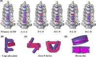
1. INTRODUCTION
Anterior cervical discectomy and fusion (ACDF) is the standard treatment for cervical spondylotic radiculopathy and myelopathy. 1 A long‐term complication resulting from ACDF, adjacent segment degeneration (ASD), can occur in both the upper and lower adjacent segments of the fusion segment; this is closely related to an increase in the facet joint force (FJF) and intradiscal pressure (IDP) in the nucleus pulposus and disc stress during long‐term exercise after ACDF. 2 , 3 The incidence of ASD after single‐level ACDF is approximately 54%, most commonly occurring at C5/6 segment. 4 However, conventional ACDF internal fixation devices (cage plus plate) are still commonly used in clinical revision surgery (RS) for patients with secondary ASD after primary ACDF. 5 Although the use of single types of these conventional devices is well‐established in revision surgeries, 5 they are less effective in improving the biomechanics of adjacent segments post‐revision compared to a combination of multiple internal fixation devices. 2 they are not ideal for restoring normal biomechanical state of spine. The emerging zero‐profile (Zero‐P) device is being increasingly applied in ACDF. Evidence shows that the Zero‐P device is superior to the traditional cage‐plus‐plate structure in reducing the incidence of ASD, adjacent segmental biomechanical responses, intraoperative blood loss, and degree of surrounding tissue injury. 6 Jin et al. 7 conducted finite element (FE) analysis on single‐ and two‐level ACDF models, compared the Zero‐P devices with cage‐plus‐plate structure, and found that the Zero‐P devices can reduce the biomechanical responses (ROM, IDP, FJF, and maximum von Mises stresses of discs) of adjacent segments. For patients with ASD after ACDF, RS further changes the abnormal sagittal sequence, and ACDF increases segmental motor loss and accelerates the occurrence of future ASD. 8 Therefore, new RS methods are urgently required to prevent ASD.
In cervical disc arthroplasty (CDA), artificial discs are placed in the degenerative segment to preserve its ROM and motor function. 9 In biomechanical studies, CDA has been shown to prevent ASD by reducing the adjacent segment ROMs and stress on intervertebral discs and facet joints, representing an advantage over ACDF. 10 Long‐term follow‐up investigations have shown that the incidence of ASD after CDA is significantly lower than that after ACDF, and the risk of secondary operations due to ASD is lower; furthermore, CDA can effectively treat the symptoms of cervical degenerative disease (CDD). 1 However, indications of the simple application of CDA in multi‐level CDD are controversial. Currently, combining ACDF and CDA as a hybrid surgery has been gradually applied in the treatment of CDD.
After ACDF, the probability of ASD occurring in both the upper and lower adjacent segments increases significantly over time. 4 Compared to single‐level ASD, achieving reduced biomechanical loads in adjacent segments is more challenging with two‐level ASD and hybrid surgery. There is a lack of biomechanical studies on different hybrid constructs when the initial fusion cage remains unchanged, particularly for cases where ASD develops both above and below the ACDF segment and requires revision surgery. 11 , 12 Additionally, the optimal surgical approach to minimize increased biomechanical loads after revision surgery remains unidentified, which is crucial for preventing recurrent ASD. Therefore, this study aims to clarify the biomechanical characteristics of adjacent segments following different RS by analyzing primary C5/6 ACDF FE models and five models of discontinuous two‐level RS after ASD at the C4/5 and C6/7 levels. The goal is to identify the most biomechanically favorable RS model to reduce the risk of ASD recurrence.
2. METHODS
2.1. Development of the intact cervical FE model
Computed tomography (CT) scans of a 30‐year‐old female participant without cervical disease were used to obtain geometric data of the C2‐T1 vertebrae (Figure 1). 2 , 3 The CT scan data were first imported into Mimics (Materialize Inc., Belgium) and transformed into a geometric structure. The geometric model was meshed in Hypermesh (Altair Engineering, Inc., USA) to generate FE models (Figure 2) and subsequently preprocessed and analyzed in Abaqus (Dassault Systemes Simulia Corporation, USA). This study protocol has been reviewed and approved by the Ethics Committee of Beijing Chaoyang Hospital, Capital Medical University (No. 2019‐ke‐212), supervised by investigator YH and PY.
FIGURE 1.
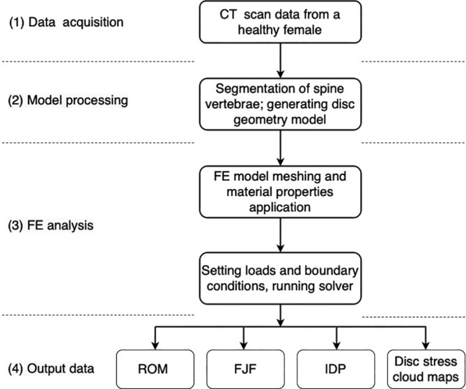
Steps involved in data acquisition, model processing, FE analysis, and output data of FE analysis for a healthy human cervical spine.
FIGURE 2.
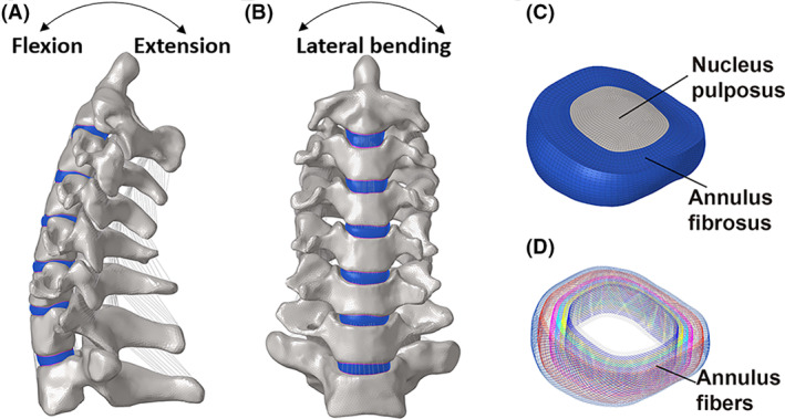
A three‐dimensional FE model of C2‐T1 was developed according to the computed tomography images of a healthy female. (A, B) The lateral and frontal views of cervical spine, (C, D) along with decomposition images of the intervertebral disc, including nucleus pulposus, annulus fibrosus and annular fibers, were shown.
The material properties in the intact and surgery FE models were assumed to be homogeneous and isotropic according to the published literature (Table 1). The vertebrae were divided into cortical bone (1mm thick) and cancellous bone meshed with tetrahedral elements. 13 The cortical endplates of the disc and facet joints were meshed using hexahedral elements. The geometric characteristics of the intervertebral discs were determined based on the dimensions of the bony endplates of the adjacent vertebrae within the same segment. The intervertebral disc was partitioned into the nucleus pulposus, annulus fibrosus, and endplates (0.5‐mm thick; Figure 2). The nucleus pulposus and annulus ground substance were meshed with hexahedral elements and occupied approximately 40% and 60% of the intervertebral disc volume, respectively. 14 Mooney‐Rivlin and Neo‐Hookean materials were used to model the nucleus pulposus and annulus ground substance, respectively. 15 Annulus fibers of eight layers modeled as hypoelastic materials with truss elements were embedded into the annulus ground substance at an inclination of approximately 30°. 16 , 17 In addition, all main ligaments were established with nonlinear tension‐only spring elements. Their geometric characteristics were defined based on the specific anatomical positions of each ligament's origin and insertion 18 : anterior longitudinal ligament (ALL), posterior longitudinal ligament (PLL), ligamentum flavum (LF), interspinous ligament (ISF), and capsular ligament (CL). 15 , 19 (Table 1).
TABLE 1.
Material properties of the cervical finite element model.
| Component | Element type | Constitutive model | Yong's modulus (MPa) | Poisson's ratio | Ref. |
|---|---|---|---|---|---|
| Cortical bone |
C3D4 C3D8 |
Isotropic elastic | E = 10 000 | ν = 0.3 | [12] |
| Cancellous bone | C3D4 | Neo‐Hookean | E = 100 | ν = 0.3 | [13] |
| Bone graft | C3D4 | Neo‐Hookean | E = 100 | ν = 0.3 | [13] |
| Nucleus pulposus | C3D8H | Mooney‐Rivlin | C 10 = 0.12, C 01 = 0.09, D 1 = 0 | – | [14] |
| Annulus ground substance | C3D8H | Mooney‐Rivlin | C 10 = 0.1333, C 01 = 0.0333, D 1 = 0.6 | – | [13] |
| Annulus fibers | T3D2 | Hypeoelastic | 350–550 | ν = 0.3 | [15] |
| Ligaments (ALL, PLL, ISL, LF, CL) | Spring | Nonlinear elastic | – | – | [16] |
| Cage (PEEK) | C3D4 | Linear elastic | E = 3760 | ν = 0.38 | [15] |
| Zero‐P device (PEEK) | C3D4 | Linear elastic | E = 3760 | ν = 0.38 | [15] |
| Plate and Screws (titanium alloy) | C3D4 | Linear elastic | E = 110 000 | ν = 0.3 | [2] |
| Bryan disc (titanium alloy) | |||||
| Outer shell (titanium alloy) | C3D8 | Linear elastic | E = 110 000 | v = 0.3 | [9] |
| Nucleus | C3D8 | Linear elastic | E = 30 | v = 0.45 | [9] |
Abbreviations: ALL, anterior longitudinal ligament; CL, capsular ligament; ISL, interspinous ligament; LF, ligamentum flavum, PLL, posterior longitudinal ligament; Zero‐P, zero‐profile.
2.2. Loading conditions of the intact models
For all FE models, moments were applied to the rigid reference point of C2, while the inferior surface of the T1 vertebrae was fully fixed in all displacement degrees of freedom. 2 To compare the C2‐T1 intact model with previously published data, a follower load of 73.6 N was imposed on C2 followed by a pure moment of 1.0 Nm. Long‐term load‐bearing can lead to bone remodeling due to metabolic effects, resulting in biomechanical changes. 21 In this study, the 73.6 N follower load is a physiological compressive load along the axial direction of the cervical spine to simulate the effect of head weight and muscle force, only used to generate the motion of cervical spine model, as widely accepted in previous studies. 22 , 23 , 24 , 25 The follower load was applied at each level through connector elements, which were created by coupling the intermediate nodes of each endplate with the endplate surface. 25 The segmental ROM of flexion, extension, lateral bending, and axial rotation was then compared with data from previously published studies.
2.3. Development of the surgery FE model
The details of the established C5/6 ACDF model and the five two‐level RS models are shown in Figure 3, and the surgical process is illustrated as follows. A cage plus plate (Medtronic Sofamor Danek, Memphis, TN, USA), ZERO‐P VA™ Zero‐P device (DePuy Synthes, Raynham, MA, USA), and Bryan cervical disc (Medtronic Sofamor Danek, Memphis, TN, USA) were implanted at the C4/5 or C6/7 segments. In the surgical segments, the intervertebral disc, ALL, and PLL were completely removed, and the three devices were subsequently implanted among the revision segments. 24 , 26 After decompression, both contact surfaces of the intervertebral devices were ensured to be in complete contact with the corresponding endplates, and the screw and plate were used to further stabilize the surgical segments. 17 , 24 The material properties of different implant devices, including screws, cage plus plate (C), Zero‐P device (Z), and Bryan disc (D), are listed in Table 1.
FIGURE 3.
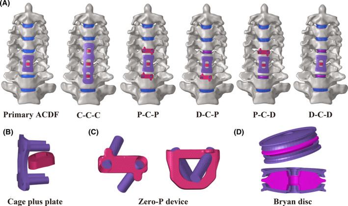
Three‐dimensional FE models of C5/6 ACDF and two‐level revision surgery constructs were developed. (A) Three‐dimensional FE model of C5/6 ACDF, C‐C‐C, P‐C‐P, D‐C‐P, P‐C‐D, D‐C‐D; three‐dimensional FE model of the (B) cage plus plate, (C) zero‐profile (Zero‐P) device, and (D) Bryan cervical disc.
2.4. Loading conditions of the revision surgery models
Under a follower load of 73.6 N, a pure moment of 1.0 Nm was applied to the C5/6 ACDF model to generate various postures in three planes. 22 , 23 , 24 , 25 Subsequently, the RS models (including C‐C‐C, P‐C‐P, P‐C‐D, D‐C‐P, and D‐C‐D) were subjected to displacement loads with the same follower load. These displacement load was applied on all RS models to match the total C2–T1 ROMs of the primary C5/6 ACDF model. The nodes in the interface region of the devices and bone were shared in the surgical models. The internal fixation system utilizes shared nodes for connections between the fixation device and screws, as well as between the screws and the bone. 17 Soft and frictionless contact properties were used to simulate the sliding contact between the cartilages of the facet joints. 22 Finally, the segmental ROM, IDP, and FJF in the RS model using either cage plus plate, Zero‐P devices, or Bryan disc during flexion‐extension, lateral bending, and axial rotation were calculated and compared with those in the C‐C‐C FE model. During extension, the mean FJFs for both left and right facet joints at the same level were recorded and calculated. The FJF during flexion was not calculated because there was no contact in the C2–T1 facet joints of the models. The FJFs on the loaded side were recorded and then averaged for the left and right loading conditions.
3. RESULTS
3.1. Comparison of the C2‐T1 FE model with previous model data
To further validate the intact model, its segmental ROMs during flexion, extension, lateral bending, and axial rotation were compared with experimental data from previously published literature. In flexion, the segmental ROMs were comparable with an in vitro study conducted by Wheeldon et al. 27 at most levels. The segmental ROMs in the present study were slightly lower compared to that in an FE model study published by Erbulut et al., 28 maximum of around 3°at C3/4 level, which is relatively close (Figure 4A). In the aspect of extension, our results were highly consistent with that of Panzer et al. 29 (FE) and Wheeldon et al. 27 (in vitro) at most levels, although a limited difference, about 2°, could be noticed at the C5/6 level (Figure 4B).
FIGURE 4.
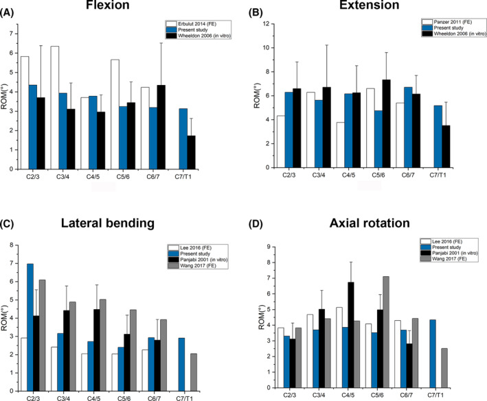
Comparison of the C2‐T1 finite element intact model with previous reported models under a 1.0 Nm moment with previously published in vitro study during (A) flexion, (B) extension, (C) lateral bending, and (D) axial rotation.
The C2/3 ROM of the intact model was higher than Panjabi et al. 28 and Lee et al. 31 during lateral bending. It was lower in C3/4 and C4/5 compared to Panjabi et al. 28 and Wang et al. 30 (Figure 4C) However, the difference was not that significant compared to that of Lee et al. in C3/4, C4/5, C5/6, and C6/7. In axial rotation, our results are in good consistence with Wang et al., 32 Lee et al. 31 and Panjabi. et al., 30 except about 4° higher at the C5/6 level compared to Wang et al.'s study 32 (Figure 4D).
3.2. Intervertebral ROM at adjacent segments and ROM distributions
Figure 5 shows the intervertebral ROMs and corresponding proportions for five RS models on three motion planes. The increase in C3/4 and C7/T1 ROMs in the C‐C‐C model was greater than those of the other RS models in all motion directions. The intervertebral ROM at segments C3/4 and C7/T1 in the P‐C‐P model were slightly smaller than or close to those in the C‐C‐C model in all motion directions. In all motion directions, the C3/4 and C7/T1 ROMs in D‐C‐P, P‐C‐D, and D‐C‐D were lower than those in C‐C‐C and P‐C‐P, being the lowest in D‐C‐D. For all RS models, the intervertebral ROM at C3/4 was slightly higher than that at C7/T1, expect for axial rotation. The segments implanted Bryan discs exhibited compensatory hyperactivity at C3/4 and C6/7 segments in the D‐C‐P and P‐C‐D models, respectively.
FIGURE 5.
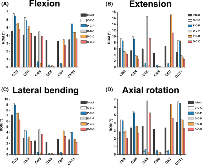
Comparison of segmental ROMs in different cervical FE models during (A) flexion, (B) extension, (C) lateral bending, and (D) axial rotation.
The percentage of the intervertebral ROM distribution for each FE model is shown in Figure 6. In the three motion planes, the intervertebral ROM distributions of two adjacent segments in the P‐C‐D, D‐C‐P, and D‐C‐D models were closer to that in the intact model. The ratio of intervertebral ROM of two adjacent segments in the D‐C‐D model was closest to the intact model.
FIGURE 6.
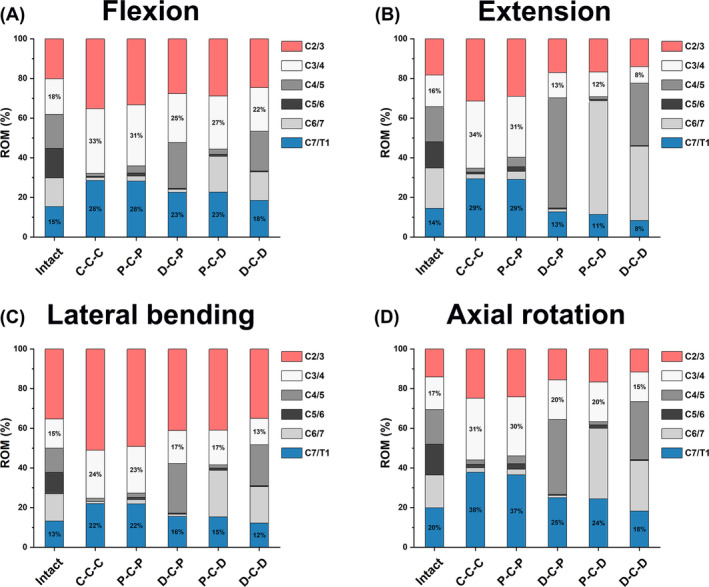
Comparison of the ROM distribution ratios in different cervical FE models during (A) flexion, (B) extension, (C) lateral bending, and (D) axial rotation.
3.3. IDP analysis of adjacent segments
The IDP values of segments C2/3, C3/4, and C7/T1 of the different FE models are shown in Figure 7. The IDP values of segments C3/4 and C7/T1 of all FE models were among 0.269–1.07 and 0.260–0.652 MPa, respectively, in different motion directions. In all motion directions, the IDP values of segments C3/4 and C7/T1 of C‐C‐C and P‐C‐P were relatively higher, whereas the IDP values of P‐C‐D, D‐C‐P, and D‐C‐D were lower, and the IDP values of the D‐C‐D models were almost the lowest (except in the extension direction). The IDPs of segments C3/4 were generally higher than those of the C7/T1 segment at flexion, lateral bending, and axial rotation, except for extension.
FIGURE 7.
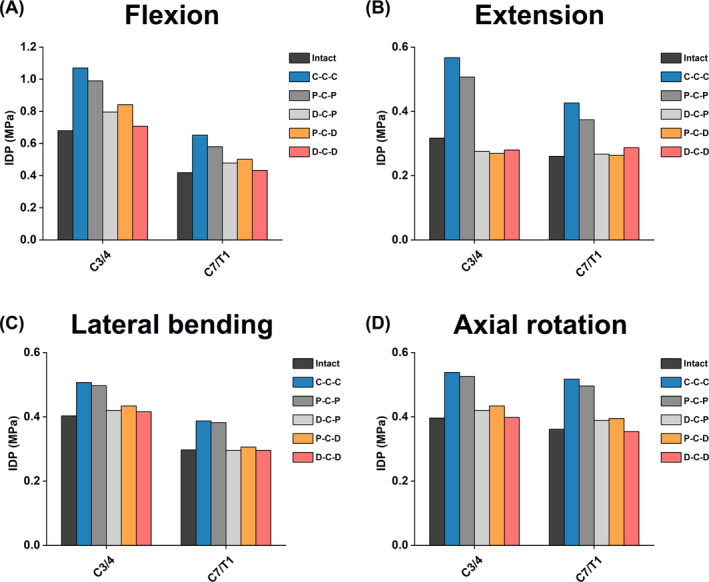
Comparison of IDP at the upper and lower adjacent segments in different cervical FE models during (A) flexion, (B) extension, (C) lateral bending, and (D) axial rotation.
3.4. Disc stress analysis of adjacent segments
The stress cloud maps of the C3/4 and C7/T1 discs in each model are shown in Figures 8 and 9, respectively. The maximum von Mises stresses in the annulus fibrosus at the C3/4 and C7/T1 discs are higher than those in the nucleus pulposus in all directions. Under flexion‐extension, lateral bending, and axial rotation, the maximum von Mises stress on the intervertebral disc is concentrated at the corresponding edge of the loading side. In all six motion directions, the highest maximum von Mises stress on the C3/4 and C7/T1 discs occurred in the C‐C‐C and P‐C‐P models, followed by P‐C‐D and D‐C‐P, with the lowest maximum von Mises stress in the D‐C‐D model. For all RS models, the maximum von Mises stress of C3/4 discs was higher than that of C7/T1 discs in all six directions.
FIGURE 8.
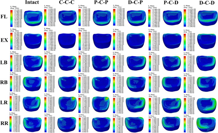
The cloud maps of C3/4 discs in different cervical FE models. Von Mises stress distribution characteristics of C3/4 intervertebral discs in different cervical FE models during flexion (FL), extension (EX), left bending (LB), right bending (RB), left rotation (LR) and right rotation (RR).
FIGURE 9.
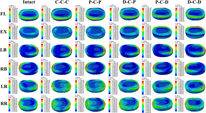
The cloud maps of C7/T1 discs in different cervical FE models. Von Mises stress distribution characteristics of C7/T1 intervertebral discs in different FE models during flexion (FL), extension (EX), left bending (LB), right bending (RB), left rotation (LR) and right rotation (RR).
3.5. FJF analysis of adjacent segments
The FJF values of the different FE models in segments C3/4 and C7/T1 are presented in Figure 10. Under all motion directions, the FJF values at C3/4 and C7/T1 segments of C‐C‐C and P‐C‐P models were higher than those of D‐C‐P, P‐C‐D, and D‐C‐D models; D‐C‐D model had the lowest FJF values at the C3/4 and C7/T1 segments. The FJFs of segments C3/4 and C7/T1 of D‐C‐P, P‐C‐D and D‐C‐D were even lower than those of the intact models during extension but higher than those of the intact models during lateral bending and axial rotation.
FIGURE 10.
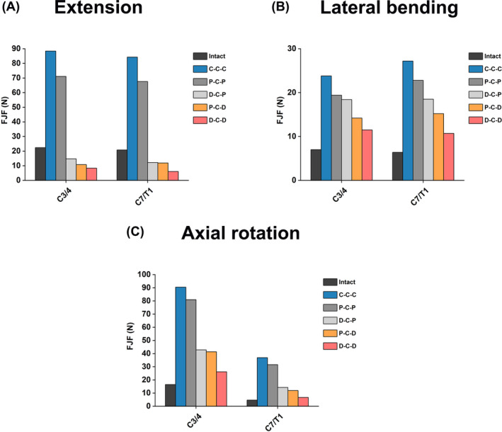
Comparison of FJFs at the upper and lower adjacent segments in different cervical FE models during (A) extension, (B) lateral bending, and (C) axial rotation.
4. DISCUSSION
In the present study, the novel hybrid revision surgery constructs with better biomechanical properties after two‐level discontinuous ASDs of primary ACDF were explored to reduce the risk of ASD recurrence. First, the validity of the C2‐T1 Intact FE model was verified by comparison with the intervertebral ROM in previously published literature, which ensured the reliability of the subsequent analysis. Segment C5/6 is among the most common segments for ASD; therefore, this segment was selected as the primary ACDF surgical segment. 4 The results showed that P‐C‐P model was slightly better than the classical C‐C‐C model in reducing biomechanical responses (intervertebral ROM, IDP, FJF, and disc stress) in both adjacent segments C3/4 and C7/T1. In the three HS models, D‐C‐P, P‐C‐D, and D‐C‐D, the intervertebral ROM, IDP, and FJF at C3/4 and C7/T1 were significantly reduced compared with those in C‐C‐C model, and IDP and FJF in D‐C‐D model were the lowest.
4.1. Simulation of motion and muscle force in cervical FE modeling analysis
In order to obtain the normal ROM of the intact model in the three motion planes, a 1.0 Nm moment was applied to the C2 vertebrae; this approach has been widely used in studies simulating the normal cervical spine ROM. 33 , 34 In FE motion simulation, the simulation of head weight and muscle force is important. Owing to the complexity of muscle modeling and motor coordination, movement after muscle modeling is more difficult and is only applied in specific cases. 35 , 36 In most studies, a follower load along the physiological curvature of the spine is typically applied to replace the action of head gravity and neck muscle force, which is a compressive force that can stabilize the spine. 3 In this study, we used the widely recognized 73.6 N follower load, which can make the FE model more closely approximate natural neck muscle function. 22 , 23 , 24 , 25 Previous research has found that the surface characteristics of screws are related to friction properties. 37 Using contact surfaces with high friction characteristics may play a beneficial role in preventing micromotion between the bone and implant, thereby reducing the chance of fretting and fatigue corrosion. 37 In our study, which focuses on the biomechanical differences of adjacent segments between different surgical models, we assume that there is no risk of screw pullout at the screw‐bone interface. Therefore, using a shared‐node approach to model the interactions between the fixation device and screws, as well as between the screws and the bone, is more reasonable for our research.
4.2. ROM analysis in adjacent segments
Increased ROM in adjacent segments after cervical fusion is the initial factor for ASD, often accompanied by increased FJF and IDP. 3 , 20 Here, without changing the C5/6 primary surgical fixation, this study explored the HS strategy with better biomechanical properties to reduce the incidence of ASD. For HS models, we selected the Zero‐P device and Bryan disc as the internal fixation devices, and no FE studies had been conducted to investigate the HS structure of these two devices combined in RS. 24 Previous studies have shown that the ROM of the Zero‐P device segment is slightly larger than that of the cage‐plus‐plate structure, and the biomechanical differences between the two internal fixation devices have been clarified. 26 The structure used two straight locking screws and a titanium alloy plate to fix two adjacent vertebral bodies, providing anterior rigid band and intersegmental fixation, so that the intersegmental ROM almost disappeared. However, the Zero‐P device was fixed to two adjacent vertebrae with one screw each; only intersegment fixation was included, without anterior rigid band fixation; this may be an important factor contributing to the slightly larger ROMs in the fusion segments when using the Zero‐P device compared with cage‐plus‐plate structure. 26 Scholz et al. 38 observed that a cage‐plus‐plate structure in vitro reduced surgical segment ROM more than Zero‐P device fusion and was therefore considered more stable. Li et al. 26 found through FE analysis that the intervertebral ROM and stresses of the disc and facet joints in the implanted adjacent segments of the Zero‐P device were slightly lower than those of the traditional cage‐plus‐plate model, which was consistent with the results of our study. In this study, the ROM, IDP, and FJF values of the C3/4 upper and C7/T1 lower adjacent segments of C‐C‐C were larger than those of P‐C‐P. However, Hua et al. 14 found no significant difference between the ROMs and IDPs of adjacent segments of the cage plus plate and Zero‐P device, this subject that required further discussion.
Compared to ACDF, the indications for CDA are stricter because of the larger segment ROM and higher incidence of cervical segmental instability in CDA. 1 Clinical and biomechanical studies have shown that surgical segment ROM can be retained after CDA, and hyperactivity can occur, which helps reduce the occurrence of ASD. 1 , 24 Furthermore, the cage‐plus‐plate fixation may stimulate hyperplasia of adjacent segments, which may be a predisposing factor for ASD; this effect can be eliminated by the Zero‐P device. 7
A major concern of this study was the change in segmental ROM before and after RS at the C4/5 and C6/7 levels. In the RS models, the intervertebral ROM in the implanted segment of the Zero‐P device was slightly higher than or close to that of the segment implanted with the titanium cage and plate in each direction of motion. The intervertebral ROM in the CDA‐operated segment was higher than that in the corresponding segment in the intact model. Notably, in the RS model, the ROMs in the adjacent segments above and below the C‐C‐C and P‐C‐P models were the largest, whereas the ROM in D‐C‐D was the smallest. In D‐C‐D, the compensation of the ROM in the upper and lower adjacent segments was more obvious than that in P‐C‐D and D‐C‐D. The ROM of segments C3/4 in all RS models was slightly higher than that of segments C7/T1; this result is consistent with that of Wong et al., 24 who found that the smaller ROM of the lower adjacent segment was at the expense of the increased ROM of the upper adjacent segment. Therefore, preoperative evaluation of the condition of the upper adjacent segment and the influence of preexisting disc degeneration on it is more important. 39 In conclusion, P‐C‐D, D‐C‐P, and D‐C‐D can effectively reduce the adjacent segment ROM in the upper and lower adjacent segments. The upper and lower adjacent segment ROMs of D‐C‐D were the smallest among all RS models, and the compensation distribution of ROM loss caused by C5/6 segment fusion was more uniform and closest to the intact model. These results indicate that the HS models containing the Bryan disc have smaller ROMs in the upper and lower adjacent segments, which helps solve the problem of severely uneven ROM distribution in multi‐segment ACDF.
4.3. IDP, disc stress, and FJF analysis in adjacent segments
In addition to the adjacent segment ROM, we focused on changes in IDP and FJF after RS. Symptoms of nerve compression caused by adjacent segment disc degeneration and facet joint degenerative hyperplasia are important reasons for revision surgery. Here, IDP was used to reflect the axial compression load on the intervertebral disc, on which the shear force, axial rotation, and lateral stress had little influence. 2 , 3 An increase in adjacent segment IDP results in greater disc bulging within our model. Different surgical approaches for cervical spine treatment, which vary in their management of facet joints and lamina, influence the extent of postoperative disc bulging, which is closely associated with pain. 40 This highlights a crucial area for future enhancement in our finite element model. For instance, the findings of Amirouche et al. 40 demonstrated that the average anterior and posterior disc bulges observed following laminectomy were comparable to those after facetectomy. Furthermore, FJF is often used to reflect the transmission of axial compression loads in facet joints under different body positions. As in our previous study, we recorded the FJF of each segment on both sides and averaged each side's FJF during flexion and extension. For lateral bending and axial rotation, only the force from the loading side was recorded. 3 Many studies have shown that a compensatory increase in ROM in adjacent fusion segments is accompanied by an increase in IDP and FJF, 2 which is consistent with our findings. Here, the IDPs of segments C3/4 and C7/T1 of the C‐C‐C model were the highest, slightly higher than those of the P‐C‐P model. The IDPs and FJFs of D‐C‐P, P‐C‐D, and D‐C‐D models were significantly lower than those of C‐C‐C and P‐C‐P models, and the maximum von Mises stress shown in the cloud map was consistent with the IDP trend. In addition, the disc stress map showed that the annular stress of the C3/4 and C7/T1 intervertebral discs was significantly higher than that of the nucleus pulposus, and the maximum disc stress occurred at the corresponding edge of the loading side. Additionally, the maximum stress on the C3/4 intervertebral disc in the upper adjacent segments of the RS model was significantly higher than that on the C7/T1 intervertebral disc; this may be related to the greater ROM of the C3/4 intervertebral disc. Shin et al. 8 also found that patients receiving three‐level fusion had greater ROM compensation in the upper adjacent segments, and ASD was more common.
4.4. Clinical significance according to the comprehensive comparison of different RS FE models
In this study, the ROM, IDP, FJF, and maximum von Mises stress in segments C3/4 and C7/T1 of the three HS structures were significantly lower than those in the C‐C‐C and P‐C‐P model, and the stress reduction in the D‐C‐P and P‐C‐D constructs was only second to that in D‐C‐D construct. The D‐C‐D model was closest to the intact model in terms of the distribution ratio of the intervertebral ROM, which was more consistent with the physiological state of the cervical spine after the initial ACDF. Among the five RS models, D‐C‐D was the most effective in preventing recurrent ASD in patients who met the CDA indications, which are relatively strict. D‐C‐P and P‐C‐D constructs can effectively prevent ASD occurrence and maintain cervical spine stability to a certain extent. Recent studies have confirmed that the CDA segments of HS constructs maintain segmental mobility without incidents of subsidence or heterotopic ossification. Significant improvements in all NDI and VAS clinical scores indicate that HS is a safe and feasible treatment option. 41 In addition, for patients who do not meet the indications for CDA, the P‐C‐P construct is superior to C‐C‐C construct in reducing the biomechanical load on the upper and lower adjacent segments, and the adjacent segments are not stimulated by titanium plate and screws when using the P‐C‐P construct.
4.5. Limitations
This study has several limitations. First, the cervical spine FE model used in the study was based on cervical spine generation in a single healthy individual, as the peculiar shape and the bone mineral density would impact the stress distribution within the vertebrae, it is not guaranteed the findings in this study is applicable in all situations. The feasibility of the established model is assessed through a comparison with previously published data and has not undergone actual in vitro validation. As previously discussed by Cappetti et al., the modeling parameters of the disc are largely responsible for the behavior of the entire segment, 42 our study determined the geometric characteristics of the intervertebral disc based on the morphology of the upper and lower endplates on CT scanning, which is a commonly used method in FE studies; however, it may cause potential bias compared to clinical situations. Besides, as the patient will not maintain a standing position for 24 h, the appliance of static loads in our model can also be a limitation. 21 Additionally, our modeling of the cervical vertebrae could be more detailed, as proven by recent studies that the inhomogeneous nature of vertebrates should be considered when generating the FE model. 43 , 44 In addition, our cervical spine model utilizes a bilayer structure consisting of cortical and trabecular bone, with fixed and uniform thickness and material properties for each layer. However, actual CT studies revealed that the cortical bone thickness in normal human anatomy was not uniform. 43 , 44 Although our approach follows common practices in FE analysis, 14 , 23 this variability could lead to discrepancies between our results and actual conditions. Therefore, future research should adopt methodologies for the proper assignment of vertebral material properties based on CT scans to achieve more scientific and accurate results. 45 , 46
5. CONCLUSION
The biomechanical responses of the upper and lower adjacent segments of the D‐C‐D, P‐C‐D and D‐C‐P hybrid models were lower than those of the C‐C‐C and P‐C‐P models, which were closer to the intact model. The D‐C‐D structure exhibited the best performance in reducing the biomechanical responses at segments C3/4 and C7/T1, and may be the best biomechanical surgical choice. P‐C‐P construct is biomechanically superior to the conventional C‐C‐C construct, and can be the best recommendation when it does not meet the indications for CDA. The findings of this study offer valuable biomechanical data reference to guide hybrid surgical decision‐making for the revision of ASD at both the upper and lower levels following single‐level ACDF. Additional biomechanical studies are necessary to further validate these conclusions and confirm their applicability.
AUTHOR CONTRIBUTIONS
YH, PY, and WL conceived and supervised the study. Material preparation, data collection and analysis were performed by WL, DS, BH and YY. WL wrote the first draft of the manuscript, and the work was critically revised by YH and PY. All authors have read and approved the final version of the manuscript, and agree with the order of presentation of the authors.
CONFLICT OF INTEREST STATEMENT
The authors have no conflict of interest.
ACKNOWLEDGMENTS
The authors would like to express their gratitude to Professor X.Q. and Professor S.C. from the Joint laboratory for Research & Treatment of Spinal Cord Injury in Spinal Deformity, Capital Medical University, for their guidence and support on this study. Thanks to the reviewers for their insightful suggestions and the effort they dedicated to improving this research. This study was supported by the Beijing Natural Science Foundation (no. 7242061), National Natural Science Foundation of China (no. 82472534), Beijing Hospital Authority Youth Programme (no. QML20230315), and Clinical Research Incubation Project, Beijing Chaoyang Hospital, Capital Medical University (no. CYFH202322).
Liang W, Sun D, Han B, Yang Y, Yin P, Hai Y. Finite element analysis of two‐level discontinuous cervical hybrid revision surgery strategy to reduce biomechanical responses of adjacent segments. JOR Spine. 2024;7(4):e70008. doi: 10.1002/jsp2.70008
Weishi Liang and Duan Sun contributed equally to this study.
Contributor Information
Peng Yin, Email: yingpeng3904@126.com.
Yong Hai, Email: yong.hai@ccmu.edu.cn, Email: prof.haiyong@yahoo.com.
REFERENCES
- 1. Findlay C, Ayis S, Demetriades AK. Total disc replacement versus anterior cervical discectomy and fusion: a systematic review with meta‐analysis of data from a total of 3160 patients across 14 randomized controlled trials with both short‐ and medium‐ to long‐term outcomes. Bone Joint J. 2018;100‐B:991‐1001. [DOI] [PubMed] [Google Scholar]
- 2. Ke W, Chen C, Wang B, et al. Biomechanical evaluation of different surgical approaches for the treatment of adjacent segment diseases after primary anterior cervical discectomy and fusion: a finite element analysis. Front Bioeng Biotechnol. 2021;9:718996. [DOI] [PMC free article] [PubMed] [Google Scholar]
- 3. Liang W, Han B, Hai Y, Yang J, Yin P. Biomechanical analysis of the reasonable cervical range of motion to prevent non‐fusion segmental degeneration after single‐level ACDF. Front Bioeng Biotechnol. 2022;10:918032. [DOI] [PMC free article] [PubMed] [Google Scholar]
- 4. Alhashash M, Shousha M, Boehm H. Adjacent segment disease after cervical spine fusion: evaluation of a 70 patient long‐term follow‐up. Spine (Phila Pa 1976). 2018;43:605‐609. [DOI] [PubMed] [Google Scholar]
- 5. Gordon AM, Elali FR, Saleh A. Revision rates after single‐level cervical disc arthroplasty versus anterior cervical discectomy and fusion: an observational study with 5‐year minimum follow‐up. Spine (Phila Pa 1976). 2024. DOI: 10.1097/BRS.0000000000005079 [DOI] [PubMed] [Google Scholar]
- 6. Kahaer A, Chen R, Maitusong M, Mijiti P, Rexiti P. Zero‐profile implant versus conventional cage‐plate construct in anterior cervical discectomy and fusion for the treatment of single‐level degenerative cervical spondylosis: a systematic review and meta‐analysis. J Orthop Surg Res. 2022;17:506. [DOI] [PMC free article] [PubMed] [Google Scholar]
- 7. Jin LY, Wei K, Feng DM, et al. Changes of adjacent segment biomechanics after anterior cervical interbody fusion with different profile design plate: single‐ versus double‐level. Comput Methods Biomech Biomed Engin. 2023;26:744‐753. [DOI] [PubMed] [Google Scholar]
- 8. Shin JJ. Comparison of adjacent segment degeneration, cervical alignment, and clinical outcomes after one‐ and multilevel anterior cervical discectomy and fusion. Neurospine. 2019;16:589‐600. [DOI] [PMC free article] [PubMed] [Google Scholar]
- 9. Yoganandan N, Purushothaman Y, Choi H, Jebaseelan D, Baisden J. Biomechanical effects of uncinate process excision in cervical disc arthroplasty. Clin Biomech (Bristol, Avon). 2021;89:105451. [DOI] [PubMed] [Google Scholar]
- 10. Purushothaman Y, Yoganandan N, Jebaseelan D, Choi H, Baisden J. External and internal responses of cervical disc arthroplasty and anterior cervical discectomy and fusion: a finite element modeling study. J Mech Behav Biomed Mater. 2020;106:103735. [DOI] [PubMed] [Google Scholar]
- 11.Liang W, Yang Y, Han B, Sun D, Yin P, Hai Y. Biomechanical Analysis of Hybrid Artificial Discs or Zero‐Profile Devices for Treating 1‐Level Adjacent Segment Degeneration in ACDF Revision Surgery. Neurospine. 2024;21:606–619. [DOI] [PMC free article] [PubMed] [Google Scholar]
- 12. Tang B, Yang J, Zhang Y, et al. Incorporating strategy in hybrid surgery for continuous two‐level cervical spondylosis from a biomechanical perspective. Comput Methods Prog Biomed. 2022;226:107193. [DOI] [PubMed] [Google Scholar]
- 13. Zhu L‐Y, Li L, Li Z‐A, et al. Design and biomechanical characteristics of porous meniscal implant structures using triply periodic minimal surfaces. J Transl Med. 2019;17:89. [DOI] [PMC free article] [PubMed] [Google Scholar]
- 14. Hua W, Zhi J, Ke W, et al. Adjacent segment biomechanical changes after one‐ or two‐level anterior cervical discectomy and fusion using either a zero‐profile device or cage plus plate: a finite element analysis. Comput Biol Med. 2020;120:103760. [DOI] [PubMed] [Google Scholar]
- 15. Sun Z, Lu T, Li J, Liu J, Hu Y, Mi C. A finite element study on the effects of follower load on the continuous biomechanical responses of subaxial cervical spine. Comput Biol Med. 2022;145:105475. [DOI] [PubMed] [Google Scholar]
- 16. Kallemeyn N, Gandhi A, Kode S, Shivanna K, Smucker J, Grosland N. Validation of a C2‐C7 cervical spine finite element model using specimen‐specific flexibility data. Med Eng Phys. 2010;32:482‐489. [DOI] [PubMed] [Google Scholar]
- 17. Lu T, Ren J, Sun Z, et al. Relationship between the elastic modulus of the cage material and the biomechanical properties of transforaminal lumbar interbody fusion: a logarithmic regression analysis based on parametric finite element simulations. Comput Methods Prog Biomed. 2022;214:106570. [DOI] [PubMed] [Google Scholar]
- 18. Yoganandan N, Kumaresan S, Pintar FA. Geometric and mechanical properties of human cervical spine ligaments. J Biomech Eng. 2000;122:623‐629. [DOI] [PubMed] [Google Scholar]
- 19. Mattucci SFE, Moulton JA, Chandrashekar N, Cronin DS. Strain rate dependent properties of younger human cervical spine ligaments. J Mech Behav Biomed Mater. 2012;10:216‐226. [DOI] [PubMed] [Google Scholar]
- 20. Khalaf K, Nikkhoo M. Comparative biomechanical analyses of lower cervical spine post anterior fusion versus intervertebral disc arthroplasty: a geometrically patient‐specific poroelastic finite element investigation. J Orthop Translat. 2022;36:33‐43. [DOI] [PMC free article] [PubMed] [Google Scholar]
- 21. Travascio F, Eltoukhy M, Cami S, Biomechanics SAJ. Altered mechano‐chemical environment in hip articular cartilage: effect of obesity. Biomech Model Mechanobiol. 2014;13:945‐959. [DOI] [PubMed] [Google Scholar]
- 22. Mo Z, Zhao Y, Du C, Sun Y, Zhang M, Fan Y. Does location of rotation center in artificial disc affect cervical biomechanics? Spine (Phila Pa 1976). 2015;40:469‐475. [DOI] [PubMed] [Google Scholar]
- 23. Yu CC, Liu P, Huang DG, Jiang YH, Feng H, Hao DJ. A new cervical artificial disc prosthesis based on physiological curvature of end plate: a finite element analysis. Spine J. 2016;16:1384‐1391. [DOI] [PubMed] [Google Scholar]
- 24. Wong C‐E, Hu H‐T, Hsieh M‐P, Huang K‐Y. Optimization of three‐level cervical hybrid surgery to prevent adjacent segment disease: a finite element study. Front Bioeng Biotechnol. 2020;8:154. [DOI] [PMC free article] [PubMed] [Google Scholar]
- 25. Moroney SP, Schultz AB, Miller JA, Andersson GB. Load‐displacement properties of lower cervical spine motion segments. J Biomech. 1988;21:769‐779. [DOI] [PubMed] [Google Scholar]
- 26. Li X‐F, Jin L‐Y, Liang C‐G, Yin H‐L, Song X‐X. Adjacent‐level biomechanics after single‐level anterior cervical interbody fusion with anchored zero‐profile spacer versus cage‐plate construct: a finite element study. BMC Surg. 2020;20:66. [DOI] [PMC free article] [PubMed] [Google Scholar]
- 27. Wheeldon JA, Pintar FA, Knowles S, Yoganandan N. Experimental flexion/extension data corridors for validation of finite element models of the young, normal cervical spine. J Biomech. 2006;39:375‐380. [DOI] [PubMed] [Google Scholar]
- 28. Erbulut DU, Zafarparandeh I, Lazoglu I, Ozer AF. Application of an asymmetric finite element model of the C2‐T1 cervical spine for evaluating the role of soft tissues in stability. Med Eng Phys. 2014;36:915‐921. [DOI] [PubMed] [Google Scholar]
- 29.Panzer MB, Fice JB, Cronin DS. Cervical spine response in frontal crash. Med Eng Phys, 2011; 33: 1147–1159. [DOI] [PubMed]
- 30. Panjabi MM, Crisco JJ, Vasavada A, et al. Mechanical properties of the human cervical spine as shown by three‐dimensional load‐displacement curves. Spine (Phila Pa 1976). 2001;26:2692‐2700. [DOI] [PubMed] [Google Scholar]
- 31. Lee JH, Park WM, Kim YH, Jahng TA. A biomechanical analysis of an artificial disc with a shock‐absorbing core property by using whole‐cervical spine finite element analysis. Spine (Phila Pa 1976). 2016;41:893‐901. [DOI] [PubMed] [Google Scholar]
- 32. Wang K, Wang H, Deng Z, Li Z, Zhan H, Niu W. Cervical traction therapy with and without neck support: a finite element analysis. Musculoskelet Sci Pract. 2017;28:1‐9. [DOI] [PubMed] [Google Scholar]
- 33. Cai XY, Sang D, Yuchi CX, et al. Using finite element analysis to determine effects of the motion loading method on facet joint forces after cervical disc degeneration. Comput Biol Med. 2020;116:103519. [DOI] [PubMed] [Google Scholar]
- 34. Mackiewicz A, Banach M, Denisiewicz A, Bedzinski R. Comparative studies of cervical spine anterior stabilization systems—finite element analysis. Clin Biomech. 2016;32:72‐79. [DOI] [PubMed] [Google Scholar]
- 35. Correia MA, McLachlin SD, Cronin DS. Optimization of muscle activation schemes in a finite element neck model simulating volunteer frontal impact scenarios. J Biomech. 2020;104:109754. [DOI] [PubMed] [Google Scholar]
- 36. Liang Z, Xu G, Liu T, Zhong Y, Mo F, Li Z. Quantitatively biomechanical response analysis of posterior musculature reconstruction in cervical single‐door laminoplasty. Comput Methods Prog Biomed. 2023;233:107479. [DOI] [PubMed] [Google Scholar]
- 37. Patel S, Solitro GF, Sukotjo C, et al. Nanotopography and surface stress analysis of Ti6Al4V bioimplant: an alternative design for stability. JOM. 2015;67:2518‐2533. [Google Scholar]
- 38. Scholz M, Schleicher P, Pabst S, Kandziora F. A zero‐profile anchored spacer in multilevel cervical anterior interbody fusion: biomechanical comparison to established fixation techniques. Spine (Phila Pa 1976). 2015;40:375‐380. [DOI] [PubMed] [Google Scholar]
- 39. Li X‐F, Lv Z‐D, Yin H‐L, Song X‐X. Impact of adjacent pre‐existing disc degeneration status on its biomechanics after single‐level anterior cervical interbody fusion. Comput Methods Prog Biomed. 2021;209:106355. [DOI] [PubMed] [Google Scholar]
- 40. Amirouche F, Solitro GF, Siemionow K, Drucker D, Upadhyay A, Patel P. Role of posterior elements in the disc bulging of a degenerated cervical spine. Int J Spine Surg. 2015;9:13. [DOI] [PMC free article] [PubMed] [Google Scholar]
- 41. Heider FC, Kamenova M, Wanke‐Jellinek L, Siepe CJ, Mehren C. Could the different surgical goals of fusion and non‐fusion also be achieved in combination within the same patient? Clinical and radiological outcome of hybrid cervical spine surgery. Eur Spine J. 2024;33:2287‐2297. [DOI] [PubMed] [Google Scholar]
- 42. Cappetti N, Naddeo A, Naddeo F, Solitro GF. Finite elements/taguchi method based procedure for the identification of the geometrical parameters significantly affecting the biomechanical behavior of a lumbar disc. Comput Methods Biomech Biomed Engin. 2016;19:1278‐1285. [DOI] [PubMed] [Google Scholar]
- 43. Garay RS, Solitro GF, Lam KC, et al. Characterization of regional variation of bone mineral density in the geriatric human cervical spine by quantitative computed tomography. PLoS One. 2022;17:e0271187. [DOI] [PMC free article] [PubMed] [Google Scholar]
- 44. Al‐Barghouthi A, Lee S, Solitro GF, Latta L, Travascio F. Relationships among bone morphological parameters and mechanical properties of cadaveric human vertebral cancellous bone. JBMR Plus. 2020;4:e10351. [DOI] [PMC free article] [PubMed] [Google Scholar]
- 45. Solitro GF, Mainnemare F, Amirouche F, Mehta A. A novel technique with reduced computed tomography exposure to predict vertebral compression fracture: a finite element study based on rat vertebrae. Med Biol Eng Comput. 2019;57:795‐805. [DOI] [PubMed] [Google Scholar]
- 46. Solitro GF, Welborn MC, Mehta AI, Amirouche F. How to optimize pedicle screw parameters for the thoracic spine? A biomechanical and finite element method study. Global Spine J. 2024;14:187‐194. [DOI] [PMC free article] [PubMed] [Google Scholar]


