

Abstract
This study presents a circularly-polarized (CP) planar monopole antenna designed for ultra-wideband (UWB) applications using characteristic mode analysis (CMA). Initially, a planar monopole antenna with a crescent moon-shaped radiator and a circular open-loop on an FR-4 substrate was designed to achieve wideband characteristics, however, this antenna only satisfied a 3 dB axial ratio (AR) bandwidth within the 8.78–9.4 GHz range. To enhance the AR bandwidth, a triangular slit, a shark fin-shaped stub, and an L-shaped strip were added to the ground plane, generating orthogonal modes in the desired frequency band using CMA. The overall dimensions of the proposed antenna are 30 × 24 × 1.6 mm2 (0.58 × 0.46 × 0.031 λ₀2). The − 10 dB S11 bandwidth is 5.73–10.78 GHz (61.21%) and the 3 dB AR bandwidth is 6–11.12 GHz (59.81%), achieving overlapped bandwidth from 6 to 10.78 GHz (56.9%). The proposed antenna has a realized gain 2.4–5.4 dBi and an average efficiency of 80% within the target frequency. A time-domain analysis, including group delay and system fidelity factor, is conducted to evaluate performance. The fabricated antenna demonstrates omnidirectional radiation patterns at various frequencies and performs well in both the time and frequency domains.
Keywords: Ultra-wideband, Characteristic mode analysis, Circularly-polarized antenna
Subject terms: Electrical and electronic engineering, Engineering
Introduction
In recent years, ultra-wideband (UWB) technology has become increasingly popular for indoor positioning due to its superior accuracy and reliability1–3. However, indoor environments present numerous obstacles, including room walls, furnishings, and people, which can cause multipath interference. In such circumstances, UWB signals follow different routes and reach the receiver at different times, resulting in distortion and inaccuracy when determining position4–8.
Circularly-polarized (CP) antennas offer a distinct advantage in mitigating multipath interference, in contrast to linearly-polarized antennas. This is due to the enhanced signal integrity of CP signals in multipath environments9,10. Consequently, CP antennas can provide stable performance in indoor positioning systems11,12. Numerous studies have been conducted on the use of UWB CP antennas for indoor positioning. The most commonly required performance characteristics of UWB CP antennas are a wide bandwidth and an omnidirectional radiation pattern13–15.
A variety of antennas has been introduced to satisfy wideband and CP characteristics by shaping the radiator or modifying the ground plane. These techniques are discussed in detail in previous studies16–28. In16,17, moon-shaped radiators were employed for the design of wideband CP antennas. In addition, antennas were proposed to enhance CP characteristics by incorporating a square slit and stub on the one-sided ground18, a square open loop and an asymmetrical ground plane19, an asymmetric radiator and a square slit20, a modified ground plane21–23, asymmetric radiators by bonding parasitic elements25,27 or cutting the radiator24,26,28. In16,17,19–21,25, the antennas achieved wide axial ratio (AR) bandwidths of 48%, 73%, 63.3%, 57.1%, 56.6%, and 45.6% respectively. However, these studies lack a time-domain analysis, which is an important feature of UWB antennas. In18,22–24, the antennas exhibited narrow AR bandwidths of 44.9%, 39.6%, 43.9%, and 21%, and the time-domain analysis was not performed. In26–28, the antennas were provided with the time-domain analysis, but the AR bandwidths were notably narrow, at 30.3%, 25%, and 25.4% respectively. Overall, antennas with a wide AR bandwidth and the time-domain analysis have not been explored.
In this study, we propose the CP antenna for UWB applications. The proposed antenna operates in the UWB 5–15 channels (6.24–10.6 GHz) above the Wi-Fi 5 GHz band. The main contribution of this work is to delineate the characteristic modes of the antenna within the frequency band of interest and to utilize orthogonal modes for CP. In addition, a comprehensive analysis of antenna performance is provided. In particular, time-domain analysis, of variables such as group delay and system fidelity, validates the antenna’s suitability for UWB applications. The proposed antenna is designed by combining various elements on a planar monopole antenna to achieve wideband performance with CP. The designed antenna initially features a radiator in the shape of a crescent moon, with an added open loop parasitic element. Additionally, the initially designed antenna is studied using characteristic mode analysis (CMA) to widen the 3 dB AR ratio bandwidth in the frequency band of interest. This is achieved by combining a triangular slit, a shark fin-shaped stub, and an L-shaped strip on the ground. As a result, the proposed antenna yields good UWB performance in the target frequency band. The remainder of this paper is organized as follows. We first present the initial design of the planar monopole antenna. Subsequently, the characteristic modes of the antenna are analyzed to create orthogonal modes for CP, and the UWB CP antenna is achieved by applying various elements. The proposed antenna is fabricated and its experimental results are presented in both the time and frequency domains. Finally, concluding remarks are provided.
Methods
Initial antenna design
As previously stated, in this work, a planar monopole antenna is employed to achieve wideband characteristics, CP, and omnidirectional radiation patterns. The dimensions of the antenna, constructed on an FR-4 substrate with a dielectric constant of 4.4 and a loss tangent of 0.02, are 24 mm × 30 mm × 1.6 mm. Figures 1 and 2 illustrate the initial antenna schematics and their performances, respectively. Initially, the dimensions of the crescent moon-shaped radiator are determined to ensure operation at the lowest frequency of interest. Note that the lowest operating frequency of a planar monopole antenna can be approximately determined by equating its area to that of an equivalent cylindrical monopole antenna29. Modification of the current flow by the crescent moon-shaped radiator results in the generation of CP16,17. Subsequently, a circular open-loop structure19 is incorporated into the crescent moon-shaped radiator design to enhance the 3 dB AR bandwidth. As shown in Fig. 3, surface current flows through the open loop of Ant. 2, facilitating CP operation at 9 GHz (which is not included in the 3 dB AR bandwidth of Ant. 1). Nevertheless, the initially designed antenna fails to satisfy the − 10 dB S11 bandwidth and 3 dB AR bandwidth within the entire target frequency range. Therefore, the following subsection will analyze the characteristic modes of the initially designed antenna and describe how its performance can be improved.
Fig. 1.

Schematics of the initial antennas (a) Ant.1 and (b) Ant.2.
Fig. 2.

Simulated results of the initial antennas (a) S11 and (b) AR.
Fig. 3.

Surface current density distributions at 9 GHz (a) Ant. 1 and (b) Ant. 2.
CMA-based design of the UWB CP antenna
In this subsection, the CMA is employed to delineate the surface current and radiating fields of the antenna structure of perfect electric conductors (PECs)30. In essence, the features of the surface current and radiating fields on the conducting structure establish the configuration and dimensions of CP antennas. The characteristic currents in a PEC structure can be calculated quantitatively31:
| 1 |
In Eq. (1),  represents the characteristic current of the
  mode, while
  denotes the complex modal weighting coefficient (MWC) corresponding to the
  mode. The MWC can be calculated using Eq. (2)32:
| 2 |
 is the modal excitation coefficient that determines the extent of the coupling between the excitation and the
  mode, and
 is the eigenvalue of the
  mode. As
  approaches zero, the associated mode exhibits resonance and achieves optimal radiation efficiency33. Modal significance (MS) assesses the potential radiation contribution of each mode. The characteristic angle (CA) represents the phase difference between the characteristic current and the corresponding characteristic field, and it can be computed using Eq. (3)34:
| 3 |
Theoretically, the following three conditions must be met to achieve an ideal CP mode35,36:
The two modes are identical with the MS of 0.707 or greater.
The phase difference of CA between the two modes is 90 degrees.
The surface current distribution between the two modes demonstrates orthogonality.
A single mode with a CA of 135° or 225° exhibits low radiation efficiency due to the high stored reactive energy. However, when the two modes with the same MS are combined, they can achieve high CP radiation efficiency. This phenomenon occurs because the inductive energy in one mode compensates for the capacitive energy in the other37–39.
Figure 4 illustrates the simulated results of the CMA for Ant. 2. Figure 4a shows that, at 9.2 GHz, the MS values for Modes 1&2 are identical and exceed 0.707. Figure 4b exhibits a CA difference of approximately 71 degrees between the two modes. The symmetric ground plane currents cancel each other out, leaving only the current from the radiator and a circular open loop. The surface current distributions on the radiator and circular open loop, as depicted in Fig. 5, confirm the orthogonality between Modes 1&2. Figure 6 displays the corresponding 3-D far-field radiation patterns at 9.2 GHz for Modes 1&2 of Ant. 2. The 3 dB AR bandwidth of Ant. 2 ranges from 8.78 GHz to 9.4 GHz (see Fig. 2b).
Fig. 4.

CMA results of Ant. 2 (a) modal significance and (b) characteristic angle.
Fig. 5.

Surface current density distributions of Ant. 2 at 9.2 GHz.
Fig. 6.

Far-field 3-D radiation patterns of Ant. 2 at 9.2 GHz.
Figure 7 illustrates the design process of the proposed antenna using CMA. The addition of a triangular slit to the right-sided ground plane in Ant. 3 results in the emergence of an additional Mode 3. Consequently, Modes 1&3 have the same MS at 7.34 GHz, as illustrated in Fig. 8a, and differ in CA by approximately 71 degrees, as shown in Fig. 8b. Furthermore, the introduction of the triangular slit alters the direction of the current on the right-sided ground, preventing cancellation of the ground plane current. The surface current distributions shown in Fig. 9 verify the orthogonality between Modes 1&3. Figure 10 shows the 3-D far-field radiation patterns at 7.34 GHz. Figure 11 demonstrates that the AR at 7.34 GHz is enhanced by approximately 17 dB in comparison to Ant. 2, resulting in an additional 3 dB AR bandwidth from 6.28 GHz to 8.2 GHz. Moreover, as shown in Fig. 11, the matching performance is improved by introducing the triangular slit.
Fig. 7.

Design process of the proposed antenna using CMA (a) Ant.3 and (b) Ant. 4.
Fig. 8.

CMA results of Ant.3 (a) modal significance and (b) characteristic angle (dashed lines: Ant. 2 modes, solid line: additional mode).
Fig. 9.

Surface current distributions of Ant. 3 at 7.34 GHz.
Fig. 10.

Far-field 3-D radiation patterns of Ant.3 at 7.34 GHz.
Fig. 11.

Simulated results of Ant. 3 (a) S11 and (b) AR.
Figure 12 presents the CMA results for Ant 4, which incorporates a shark fin-shaped stub and an L-shaped strip on the ground plane. At 8.43 GHz and 11.05 GHz, the MS values for both Modes 4&5 and Modes 5&6 are identical, with CA differences of approximately 87 degrees and 70 degrees, respectively. The surface current distribution, as depicted in Fig. 13, validates the orthogonality between Modes 4&5 and Modes 5&6. Figure 14 illustrates the 3-D radiation pattern for each mode. Notably, three additional modes that contribute to CP are observed, leading to an enhanced 3 dB AR bandwidth. It is additionally observed that the impedance bandwidth of Ant. 4 is enhanced in comparison to that of Ant. 3. Consequently, Ant. 4 exhibits a bandwidth of 5.79 GHz to 11.12 GHz (63%) for 10 dB S11 and 5.94 GHz to 11.22 GHz (61.5%) for the 3 dB AR, encompassing the UWB 5–15 channels (6.24–10.6 GHz) as shown in Fig. 15. The design process is depicted in a flow diagram in Fig. 16.
Fig. 12.

CMA results of Ant.4 (dashed lines: Ant. 3 modes, solid lines: additional modes). (a) Modal significance and (b) characteristic angle.
Fig. 13.

Surface current distributions of Ant. 4 (a) 8.43 GHz and (b) 11.05 GHz.
Fig. 14.

Far-field 3-D radiation patterns of Ant.4 (a) 8.43 GHz and (b) 11.05 GHz.
Fig. 15.

Simulated results of Ant. 4 (a) S11 and (b) AR.
Fig. 16.

Flow diagram of the proposed antenna design process.
Time-domain analysis
In UWB applications, time-domain analysis of the antenna should be performed to assess the potential for distortion and to evaluate the signal quality, focusing on the group delay and system fidelity factor (SFF)40,41.
The group delay ( is a metric employed to assess the overall phase
  ) distortion within an antenna system. The average group delay represents the time required for a signal to traverse from one antenna terminal to the other. This parameter offers a valuable measure of the system’s temporal characteristics42:
| 4 |
The SFF employs a standard parameter to compare the received signal ( ) and the transmitted signal (
 ) across two antennas. This parameter serves to quantify the extent to which the antenna system influences the input pulse43,44:
| 5 |
To validate the group delay and SFF of the designed UWB CP planar monopole antenna, two identical antennas are spaced 500 mm apart. These antennas are positioned in both face-to-face and side-by-side configurations, as illustrated in Fig. 17. Figure 18a, b indicate good simulated performances of the phase and group delay for the two proposed antennas positioned face-to-face and side-by-side. The face-to-face configuration exhibits an SFF of 83.3%, and the side-by-side arrangement yields an SFF of 92.3%, as depicted in Fig. 18c,d.
Fig. 17.

Configuration of the two proposed antennas for time-domain analysis (a) face-to-face and (b) side-by-side.
Fig. 18.

Simulated time-domain results (a) phase, (b) group delay, (c) system fidelity of normalized signals in the face-to-face case, and (d) system fidelity of normalized signals in the side-by-side case.
Measurement results
The designed UWB CP planar monopole antenna was fabricated and measured, as depicted in Fig. 19. As demonstrated in Fig. 20, the measured − 10 dB S11 bandwidth and 3 dB AR bandwidth of the fabricated UWB antenna were 5.73 GHz to 10.78 GHz and 6 GHz to 11.12 GHz, respectively. The measurement results align closely with the simulation results, with slight discrepancies attributed to fabrication and measurement errors. Figure 21 shows the simulated and measured realized gain and radiation efficiency of the proposed antenna, which has a realized gain from 2.4 to 5.4 dBi and an average efficiency of 80% within the target frequency. Figure 22 illustrates the phase and group delay of S21 for the two proposed antennas positioned face-to-face and side-by-side. The measured phase and group delay align closely with the simulated results, demonstrating good agreement between experimentation and simulation. The radiation patterns of right-handed circular polarization (RHCP) and left-handed circular polarization (LHCP) measured at different frequencies are indicated in Fig. 23. The measured radiation patterns are similar to the simulated radiation patterns, and omnidirectional radiation patterns can be observed.
Fig. 19.

Fabrication and measurement setup of the proposed UWB CP planar monopole antenna (a) fabrication and (b) measurement setup.
Fig. 20.

Simulated and measured results of the proposed antenna (a) S11 and (b) AR.
Fig. 21.

Simulated and measured results of the proposed antenna in the target frequency bandwidth (a) realized gain and (b) radiation efficiency.
Fig. 22.

Measured phases and group delays of the two proposed antennas from a distance of 500 mm in the target frequency bandwidth (a) phase and (b) group delay.
Fig. 23.
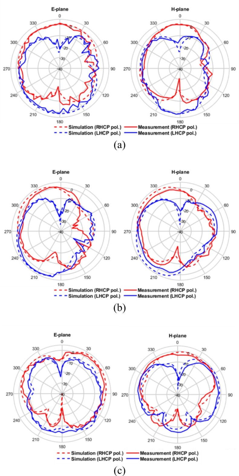
Simulated and measured radiation patterns (a) 6.7 GHz, (b) 8.7 GHz, and (c) 10.2 GHz.
Table 1 presents a comparative analysis of the proposed CP planar monopole antenna with previous CP planar monopole antennas21,22,39–44. The variable λ0 represents the wavelength at the lowest frequency of the operating bandwidth in free space. As summarized in the table, a time-domain analysis was not provided for the antennas except in42–44. Therefore, most of these antennas have not been fully validated for use in UWB applications. In42–44, the authors performed a time-domain analysis for validating UWB performance. However, the overlapped bandwidths for − 10 dB S11 and 3 dB AR of the antennas proposed in42–44 are narrow, and the antenna size in43,44 is large. Considering the overall performances of the antennas, it is evident that the proposed antenna is the most suitable candidate for use in UWB applications.
Table 1.
Comparison of CP planar monopole antennas.
| Ref. | Antenna size ( ) ) |
-10 dB S11 & 3 dB AR overlapping bandwidth (GHz) | Peak gain (dBi) | Average radiation efficiency (%) | Time-domain analysis | Analysis method |
|---|---|---|---|---|---|---|
| 21 | 0.59 0.49 0.49 |
5.91–10.6 (56.8%) | 5.67 | N/A | N/A | Full-wave method |
| 22 | 0.66 0.66 0.66 |
4.75–7.1 (39.6%) | 4 | 70 | N/A | Full-wave method |
| 23 | 0.4 0.3 0.3 |
5.5–8.6 (43.9%) | 6 | 90 | N/A | Modal analysis method |
| 24 | 0.5 0.47 0.47 |
5.95–7.35 (21%) | 4.59 | N/A | N/A | Full-wave method |
| 25 | 0.55 0.46 0.46 |
2.2–3.5, (45.6%) | 3.5 | 82 | N/A | Full-wave method |
| 26 | 0.38 0.45 0.45 |
3.35–4.55 (30.3%) | 4.3 | N/A | Yes | Full-wave method |
| 27 | 1.21 0.9 0.9 |
4.21–5.42 (25%) | 4.92 | 72 | Yes | Full-wave method |
| 28 | 1.16 1.18 1.18 |
7.58–9.79 (25.4%) | 4.32 | 82 | Yes | Full-wave method |
| This work | 0.6 0.48 0.48 |
6–10.78 (56.9%) | 5.4 | 80 | Yes | Modal analysis method |
Conclusion
In this study, the UWB CP planar monopole antenna is proposed to operate in the UWB 5–15 channels (6.24–10.6 GHz). The proposed antenna incorporates a series of shape modifications in a stepwise manner using CMA to achieve CP within the target frequency bandwidth. The proposed antenna demonstrates excellent UWB performance, achieving an overlapped bandwidth of 6 GHz to 10.78 GHz. Measurement results closely align with simulation results, validating the performance of the antenna. The group delay and SFF are demonstrated through face-to-face and side-by-side configurations, emphasizing its practical applicability in the context of UWB applications.
Author contributions
H.H. wrote the paper and performed the simulations. H.H. and M.-J.K. fabricated the antenna and performed the measurement. S.P., J.L., and L.Q. addressed the technical concerns about the antenna simulation and measurement. K.-Y.J. revised the manuscript, and supervised the entire work. All authors contributed to the writing of the manuscript.
Data availability
The datasets used and/or analyzed during the current study are available from the corresponding author upon reasonable request.
Declarations
Competing interests
The authors declare no competing interests.
Footnotes
Publisher’s note
Springer Nature remains neutral with regard to jurisdictional claims in published maps and institutional affiliations.
References
- 1.Coppens, D. et al. An overview of UWB Standards and Organizations (IEEE 802.15.4, FiRa, Apple): interoperability aspects and future research directions. IEEE Access.10, 70219–70241 (2022). [Google Scholar]
- 2.Din, I. U. et al. A novel compact ultra-wideband frequency-selective surface-based antenna for gain enhancement applications. J. Electromagn. Eng. Sci.23 (2), 108–121 (2023). [Google Scholar]
- 3.Xu, Z. et al. Optical generation of UWB pulses utilizing Fano resonance modulation. Front. Optoelectron.14 (4), 426–437 (2021). [DOI] [PMC free article] [PubMed] [Google Scholar]
- 4.Mekki, K., Necibi, O., Lakhdhar, S. & Gharsallah, A. A UHF/UWB monopole antenna design process integrated in an RFID reader board. J. Electromagn. Eng. Sci.22 (4), 479–487 (2022). [Google Scholar]
- 5.Youn, S., Jang, B. J. & Choo, H. Design of a UWB antenna with multiple ports on a single circular radiator for direction-finding applications. J. Electromagn. Eng. Sci.23 (1), 63–68 (2023). [Google Scholar]
- 6.Chilukuri, S. & Gundappagari, S. A wide dual-band metamaterial-loaded antenna for wireless applications. J. Electromagn. Eng. Sci.20 (1), 23–30 (2020). [Google Scholar]
- 7.Saleh, A. A. M. & Valenzuela, R. A statistical model for indoor multipath propagation. IEEE J. Sel. Areas Commun.SAC-5 (2), 128–137 (1987). [Google Scholar]
- 8.Zayets, A. & Steinbach, E. Robust WiFi-based indoor localization using multipath component analysis. In Proc. Int. Conf. Indoor Positioning Indoor Navigat. (IPIN) 1–8 (2017).
- 9.Choi, S. & Sung, Y. Simple dual-feed dual-circular polarization antenna with high isolation. J. Electromagn. Eng. Sci.23 (2), 154–164 (2023). [Google Scholar]
- 10.Nkinbeng, C. H. S., Wang, H., Byun, G., Park, Y. B. & Park, I. Non-uniform metasurface-integrated circularly polarized end-fire dipole array antenna. J. Electromagn. Eng. Sci.23 (2), 109–121 (2023). [Google Scholar]
- 11.Al-Gburi, A. J. A. et al. Broadband circular polarised printed antennas for indoor wireless communication systems: a comprehensive review. Micromachines. 13 (7), 1048 (2022). [DOI] [PMC free article] [PubMed] [Google Scholar]
- 12.Chen, Y. et al. UWB system for indoor positioning and tracking with arbitrary target orientation, optimal anchor location, and adaptive NLOS mitigation. IEEE Trans. Veh. Technol.69 (9), 9304–9314 (2020). [Google Scholar]
- 13.Ullah, U., Al-Hasan, M., Koziel, S. & Mabrouk, I. B. Circular polarization diversity implementation for correlation reduction in wideband low-cost multiple-input-multiple-output antenna. IEEE Access.8, 95585–95593 (2020). [Google Scholar]
- 14.Li, W., Xue, W., Li, Y., Chung, K. & Huang, Z. A wideband differentially fed circularly polarized slotted patch antenna with a large beamwidth. J. Electromagn. Eng. Sci.23 (6), 512–520 (2023). [Google Scholar]
- 15.Brás, L., Carvalho, N. B., Pinho, P., Kulas, L. & Nyka, K. A review of antennas for indoor positioning systems. Int. J. Antennas Propag. 2012, 1–14 (2021).
- 16.Hu, B., Shen, Z. & Nasimuddin & Broadband circularly polarized moon-shaped monopole antenna. Microw. Opt. Technol. Lett.57, 1135–1139 (2015). [Google Scholar]
- 17.Samsuzzaman, M. & Islam, M. Circularly polarized broadband printed antenna for wireless applications. Sensors. 18 (12), 4261 (2018). [DOI] [PMC free article] [PubMed] [Google Scholar]
- 18.Zhang, L., Jiao, Y. C., Ding, Y., Chen, B. & Weng, Z. B. CPW-fed broadband circularly polarized planar monopole antenna with improved ground-plane structure. IEEE Trans. Antennas Propag.61 (9), 4824–4824 (2013). [Google Scholar]
- 19.Ding, K., Guo, Y. X. & Gao, C. CPW-fed wideband circularly polarized printed monopole antenna with open loop and asymmetric ground plane. IEEE Antennas Wirel. Propag. Lett.16, 833–836 (2017). [Google Scholar]
- 20.Chen, Q., Zhang, H. & Yang, L. C. Compact CPW-fed dual-band linearly and circularly polarized monopole antenna for Wimax/WLAN applications. In Proc. Int. Conf. Microw. Millim. Wave Technol. (ICMMT), 1–3 (2018).
- 21.Chaudhary, P. & Kumar, A. Compact ultra-wideband circularly polarized CPW-fed monopole antenna. AEU- Int. J. Electron. Commun.107, 137–145 (2019). [Google Scholar]
- 22.Krishna, R. R., Kumar, R. & Kushwaha, N. A circularly polarized slot antenna for high gain applications. AEU- Int. J. Electron. Commun.68 (11), 1119–1128 (2014). [Google Scholar]
- 23.Ghanbari, L., Keshtkar, A. & Jarchi, S. Characteristic mode analysis of a flexible circularly polarized UWB antenna for wireless body area networks. Wirel. Netw. 1–15 (2024).
- 24.Ma, Z., Chen, J., Chen, P. & Jiang, Y. F. Design of planar microstrip ultrawideband circularly polarized antenna loaded by annular-ring slot. Int. J. Antennas Propag.2021 (10), 1–10 (2021). [Google Scholar]
- 25.Das, S., Islam, H., Bose, T. & Gupta, N. Ultra wide band CPW-fed circularly polarized microstrip antenna for wearable application. Wirel. Pers. Commun.108 (1), 87–103 (2019). [Google Scholar]
- 26.Park, S., Qu, L., Park, M. S. & Jung, K. Y. Design of a circularly polarized planar monopole antenna with a simplified radiator structure for UWB application. J. Electromagn. Eng. Sci.24 (2), 145150 (2024).
- 27.Behera, B. R., Srikanth, P., Meher, P. R. & Mishra, S. K. A compact broadband circularly polarized printed monopole antenna using twin parasitic conducting strips and rectangular metasurface for RF energy harvesting application. Int. J. Electron. Commun.120, 153233 (2020). [Google Scholar]
- 28.Meher, P. R. & Mishra, S. K. Design and development of mathematical equivalent circuit model of broadband circularly polarized semi-annular ring-shaped monopole antenna. Prog Electromagn. Res. C. 129, 73–87 (2023). [Google Scholar]
- 29.Park, S. & Jung, K. Y. Novel compact UWB planar monopole antenna using a ribbon-shaped slot. IEEE Access.10, 61951–61959 (2022). [Google Scholar]
- 30.Khan, R. et al. Enhancing gain and isolation of a quad-element MIMO antenna array design for 5G sub-6 GHz applications assisted with characteristic mode analysis. Sci. Rep.14, 11111 (2024). [DOI] [PMC free article] [PubMed] [Google Scholar]
- 31.Sharma, A. et al. Design of compact wideband circularly polarized hexagon-shaped antenna using characteristics mode analysis. IEEE Trans. Instrum. Meas.70, 1–8 (2021).33776080 [Google Scholar]
- 32.Harrington, R. F. & Mautz, J. R. Theory of characteristic modes for conducting bodies. IEEE Trans. Antennas Propag.AP-19 (5), 622–628 (1971). [Google Scholar]
- 33.Wen, D. L., Hao, Y., Wang, H. Y. & Zhou, H. Design of a wideband antenna with stable omnidirectional radiation pattern using the theory of characteristic modes. IEEE Trans. Antennas Propag.65 (5), 2671–2676 (2017). [Google Scholar]
- 34.Elias, B. B. Q., Soh, P. J., Al-Hadi, A. A., Akkaraekthalin, P. & Vandenbosch, G. A. E. A review of antenna analysis using characteristic modes. IEEE Access.9, 98833–98862 (2021). [Google Scholar]
- 35.Supreeyatitikul, N., Lertwiriyaprapa, T., Krairiksh, M. & Phongcharoenpanich, C. CMA-based four-element broadband circularly polarized octagonal-ring slot antenna array for S-band satellite applications. IEEE Access.10, 130825–130838 (2022). [Google Scholar]
- 36.Supreeyatitikul, N., Janpangngern, P., Lertwiriyaprapa, T., Krairiksh, M. & Phongcharoenpanich, C. CMA-based quadruple-cluster leaf-shaped metasurface-based wideband circularly-polarized stacked-patch antenna array for sub-6 GHz 5G applications. IEEE Access.11, 14511–14523 (2023). [Google Scholar]
- 37.Chen, Y. & Wang, C. F. Characteristic Modes: Theory and Application to Antenna Engineering (Wiley, 2013).
- 38.Han, M. & Dou, W. Compact clock-shaped broadband circularly polarized antenna based on characteristic mode analysis. IEEE Access.7, 159952–159959 (2023). [Google Scholar]
- 39.Newman, E. H. Small antenna location synthesis using characteristic modes. IEEE Trans. Antennas Propag.AP-27 (4), 530–531 (1979). [Google Scholar]
- 40.Brande, Q. V. D., Lemey, S. & Rogier, H. Planar sectoral antenna for IRUWB localization with minimal range estimation biasing. IEEE Antennas Wirel. Propag. Lett.20 (2), 135–139 (2021). [Google Scholar]
- 41.Nejdi, I. H. et al. UWB circular fractal antenna with high gain for telecommunication applications. Sensors. 23 (8), 4172 (2023). [DOI] [PMC free article] [PubMed] [Google Scholar]
- 42.Quintero, G., Zurcher, J. F. & Skrivervik, A. K. System fidelity factor: a new method for comparing UWB antennas. IEEE Trans. Antennas Propag.59 (7), 2502–2512 (2011). [Google Scholar]
- 43.Jiang, Z., Xiao, S. & Li, Y. A wide-angle time-domain electronically scanned array based on energy-pattern reconfigurable elements. IEEE Antennas Wirel. Propag.17 (9), 1598–1602 (2018). [Google Scholar]
- 44.Lasemi, Z. & Atlasbaf, Z. Impact of fidelity factor on breast cancer detection. IEEE Antennas Wirel. Propag. Lett.19 (10), 1649–1653 (2020). [Google Scholar]
Associated Data
This section collects any data citations, data availability statements, or supplementary materials included in this article.
Data Availability Statement
The datasets used and/or analyzed during the current study are available from the corresponding author upon reasonable request.