Abstract
The aim of this research is to develop thermoplastic olefin (TPO) composites containing polypropylene (PP), an elastomeric ethylene-octene copolymer (EOC) and graphene nanoplatelets (GNPs), suitable for material extrusion (MEX). A PP functionalized with amino-pyridine (PP-g-Py) was used as a compatibilizer. The composite blends had droplet-matrix morphology at compositions as high as 40 wt% EOC. Imaging by Transmission Electron Microscopy showed that the GNPs resided at the interface between the blend components. This microstructure promoted higher thermal conductivity of the TPO/GNP composite blends, as compared to the PP/GNP composite (1.54 W/m K, vs 1.3 W/m K respectively). PP/GNP composites processed by MEX exhibited inadequate interfacial fusion between the deposited strands, which resulted in severe delamination during tensile and flexural testing, and consequently poor mechanical properties. In the TPO/GNP composites containing 40 wt% EOC, the slower crystallization of the elongated EOC domains promoted interfacial adhesion between the strands, resulting in better part consolidation, more consistent mechanical properties and improved ductility compared to the PP/GNP composites.
Keywords: Material extrusion, thermoplastic olefin blends, graphene nanoplatelets, nanocomposites, morphology
Introduction
Material extrusion (MEX) 3D printing is used extensively to fabricate thermoplastic parts with complex geometries that cannot be easily produced by conventional manufacturing methods. 1 Processing of thermoplastic-based nanocomposites containing conductive fillers, such as carbon nanotubes (CNTs) and graphene nanoplatelets (GNPs) by MEX, has attracted a lot of interest, because it can produce parts having functional properties, including thermal and electrical conductivity, in combination with good mechanical properties.2,3 Additionally, the aerospace industry’s engagement with additive manufacturing reflects a significant trend towards leveraging these technologies for their efficiency, the potential for intricate designs, and their contribution to lightweighting and sustainability in aerospace components. 4
The GNPs act as reinforcing and nucleating agents when added to thermoplastic matrices. Increases in the elastic modulus and tensile strength were reported in 3D printed composites based on polyamide (PA) 12 and linear low-density polyethylene (LLDPE) matrices containing GNPs.5,6 Incorporating GNPs also increased the electrical and thermal conductivity of polymer composites.5,7,8 Shmueli et al. showed that the thermal conductivity of PP-GNP composites was directional. 8 The conductivity along the in-plane direction was 180 % higher than the through-plane direction and 138% higher than the molded sample. They also showed that the alignment of GNPs during extrusion induced shear thinning behaviour as the composite melt was extruded through the nozzle, and affected the crystallization behaviour.
Thermoplastics with large coefficients of thermal expansion (CTE) can build higher thermal stresses due to excessive expansion or contraction, thus resulting in deformed printed structures during the cooling stage of the MEX process. Wei et al. 9 demonstrated using thermal mechanical analysis (TMA) that composites containing acrylonitrile-butadiene-styrene (ABS) and graphene exhibited less than 1% expansion, which alleviated thermal deformation during printing, therefore enabling better shape retention. 9 This can promote high resolution in printing, and improve the integrity of the resulting printed structures. In parallel, reinforcing PP with graphene has been identified as another effective approach to combat these dimensional instabilities, underlining PP’s potential for 3D printing applications when modified appropriately. 10
The GNP content and dispersion affect significantly the thermorheological properties of the melts, and the selection of processing parameters. Yang et al. and Carmago et al. investigated the printing parameters to achieve smooth extrusion of poly(vinyl alcohol), polylactic acid, and PA6 composites.11–13 However, they encountered challenges during the printing of the composite melts, especially at high filler concentrations. Wei et al. 9 reported that GNP aggregation clogged the nozzle, causing discontinuous extrusion of ABS.
A particular challenge in MEX processing is the poor adhesion between printed strands, and the shrinkage and warpage of the printed structures, which are exacerbated when printing highly crystalline polymers such as PP. Ho and Kontopoulou 14 showed that this can be mitigated by blending PP with a low melting point thermoplastic elastomer, to produce thermoplastic olefin (TPO) blends. Due to its slow crystallization the EOC acted as a binder to improve the fusion between the deposited strands, and prevented excessive warpage. 14
The objective of this research is to develop TPO-GNP composites that are suitable for processing by MEX. We previously demonstrated that using a pyridine-grafted-polypropylene (PP-g-Py) as a compatibilizer facilitated the dispersion of the GNPs within a PP matrix, resulting in significant improvements in the properties of the thermoplastic matrix. 15 In this work, we process these composites by MEX, and we demonstrate that the resulting printed structures suffer from poor adhesion between the strands, resulting in severe delamination during mechanical testing. Adding the elastomeric EOC to the composites facilitated the interfacial fusion between the strands, thus improving the structural integrity of the composites. Given that TPOs have many industrial applications, especially in the automotive industry, 16 the successful processing of their composites with GNPs can result in functional products that have improved mechanical properties.
Experimental
Materials
A homopolymer PP, Pro-faxTM PDC 1274 (MFR = 12 g/10 min @ 230°C/2.16 kg), was supplied from LyondellBasell. Maleic anhydride-modified polypropylene (PP-g-MA, POLYBOND® 3150, maleic anhydride content 0.5 wt%, MFI = 52 g/10 min @230°C/2.16 kg) was purchased from ChemPoint Inc. A poly(ethylene-co-octene) (EOC) polyolefin elastomer, ENGAGETM 8200, 38 wt% comonomer content, density of 0.87 g/cm3, MFI = 5 g/10 min @ 190°C/2.16 kg) was obtained from Dow Inc. Antioxidant (Irganox® 1010, purity 98%), 4-aminomethylpyridine (AMP) (purity >98%, boiling point 230°C), p-xylene (anhydrous, ≥99%), and graphite flakes (−325 mesh, >99% carbon basis) were purchased from Sigma–Aldrich, Canada. All polymer materials and chemicals were used as received.
GNPs were produced from flake graphite (Sigma Aldrich, Canada) using a thermomechanical exfoliation (TME) process, which separates graphite into its constituent layers under the action of shear. 17 This process produces mixtures of few and multi-layered graphene, with minimal defects and no surface functional groups. The resulting GNPs have a specific surface area ranging between 300 and 430 m2/g.
Synthesis of Compatibilizer and Composite Preparation
A Rheomix R600 batch mixer, equipped with two counterrotating roller rotors and connected to a Haake Polylab torque rheometer was used to synthesize PP-g-Py and to melt compound the blends and composites. The synthesis of the PP-g-Py compatibilizer from PP-g-MA was described previously 15 ; a PP/PP-g-Py ratio of 90/10 (noted as PP in the analysis below for simplicity) was used. For the preparation of the blends, ratios of 80/20 and 60/40 by weight PP/EOC were used. To prepare composites and blends, PP/PP-g-Py, EOC and GNPs were added to the preheated chamber together with the antioxidant (0.5 wt%). The compounding time was 7 min, at a temperature of 190°C with a rotor speed of 100 r/min. Table 1 presents the compositions of the resulting blends and composites.
Table 1.
Composition of composites and blends (based on 100 g composite).
| Abbreviations | PP (g) | EOC (g) | GNP (g) |
|---|---|---|---|
| PP a | 100 | 0 | 0 |
| PP-15GNP | 85 | 0 | 15 |
| PP-20EOC | 80 | 20 | 0 |
| PP-40EOC | 60 | 40 | 0 |
| PP-20EOC-15GNP | 68 | 17 | 15 |
| PP-40EOC-15GNP | 51 | 34 | 15 |
aDenotes PP/PP-g-Py 90/10.
Material Extrusion
An Allevi 1 Bioprinter by Allevi Inc. was used for the MEX processing. An air compressor (Senco, model PC1010) was used to supply compressed air to the printer. Based on previous work, 14 a pneumatic extrusion pressure of 80 lbf/in2(552 kPa) was used, which is the maximum pressure that can be achieved by the instrument. The extrusion temperature was chosen as 210°C; this temperature is low enough to avoid excessive degradation of the PP, while allowing for lower viscosity and reasonable extrusion rates. 14
The blends and composites produced by melt compounding were chopped, loaded into the metal syringe, and preheated at 210°C. The thermoplastic melt was extruded through the conical reservoir to the needle before exiting the nozzle. The nozzle consists of a tapered reservoir and a cylindrical needle with an inside diameter of 600 μm, 14 and is connected to the metal syringe through a threaded luer lock. A heat gun was used to blow hot air to the build platform below the nozzle and maintain its temperature at 120°C.
The following control parameters and settings were selected: layer height of 0.6 mm, infill distance of 0.6 mm, and a print speed (speed of the nozzle moving in the horizontal directions) in the 2.5–5.0 mm/s range. Digital designs of the structures were built using the Allevi Bioprint software or loaded to the software in GCODE or STL formats.
Tensile and Interfacial Shear Strength Tests
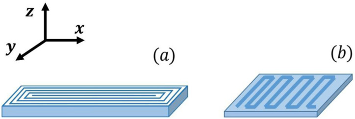
A Universal Tester (Instron 3369) was used to carry out the tensile tests at room temperature, according to the ASTM D638 standard. The test speed was 10 mm/min. A concentric print pattern, illustrated in Figure 1(a) was followed under the conditions mentioned in Section 2.3 to print samples with dimensions 70 mm × 10 mm × 3.2 mm. A Type V die was used to punch dumbbell-shaped specimens out from the printed samples. Five replicates were tested for each composition.
Figure 1.
Illustration of printing patterns in a specimen for (a) the tensile test (b) and flexural test.
A modified flexural test protocol was adopted to measure the flexural strength of the MEX printed samples, using the model 3369 Instron universal testing machine. According to the ASTM D1184 standard,18,19 rectangular specimens with the dimensions of 31 mm 19 mm 3 mm (length depth thickness) were used, with a span of 30 mm between the supports, and the test speed was 0.321 mm/min. The specimens were printed in a zigzag pattern along the length of 19-mm width (y-direction, Figure 1(b)). This printing pattern was chosen, because it demonstrates the sensitivity of the printed specimens to interfacial failure, as suggested by Wang and Gardner. 19
Rheological Characterization
Compression molded samples 20 mm in diameter and 1 mm in thickness were prepared at 190°C, under 12 bar for 1 min using a Carver Press. Rheological characterization was conducted in a stress-controlled rheometer, ViscoTech by Reologica, equipped with 20-mm parallel plate fixtures. Samples were loaded to the chamber, and pre-heated at test temperatures to a gap of 1 mm, followed by a wait time of 3 min to allow uniform melting. The linear viscoelasticity region was determined through stress sweeps from 0.1 Pa to 1000 Pa, at an angular frequency of 1 rad/s. Frequency sweeps were performed in the oscillatory mode at a frequency range of 0.06–150 rad/s and at 210°C.
Imaging
Scanning and Transmission electron microscopy (SEM, and TEM) were employed to observe the morphology of the composites. Surfaces were prepared by sectioning using a Leica Microsystems EM UC7/RC7 cryo-ultramicrotome at −100°C equipped with a diatom diamond knife (Diatome, Nidau, Switzerland).
For TEM, ultrathin sections of ∼50 to 70 nm thickness were transferred onto 200-mesh Cu grids with Formvar support film (Electron Microscopy Sciences, Hatfield, PA, USA). The grids were vapour stained with RuO4 (Structure Probe, Inc. West Chester, PA, USA) in a covered glass Petri dish. Two hours of staining at room temperature was determined as the optimum duration to obtain good contrast. The RuO4 solution was replaced every 30 min to maintain a constant reaction rate. The grids were imaged by the Thermo Scientific Talos F200X G2 (S)TEM equipped with a Ceta 16M CMOS camera at an accelerating voltage of 200 keV (Thermo Scientific, Hillsboro, OR, USA).
The flat cryo-sectioned surfaces were also imaged by an FEI Helios Nanolab 660 DualBeam (Thermo Scientific, Hillsboro, OR USA) Scanning Electron Microscope (SEM) at an accelerating voltage of 2 kV, beam current of 0.40 nA and working distance of 4 mm in secondary electron (SE) mode with Everhart-Thornley SE Detector (ETD) and Through the Lens Detector (TLD).
A color video camera Sony 3CCD connected to an optical stereomicroscope (Olympus SZ-PT, Japan) was used to observe the specimens after tensile tests.
Differential Scanning Calorimetry
Differential scanning calorimetry (DSC) measurements were conducted using a DSC Q1000 by TA Instruments. Samples weighing 5–15 mg, were placed in a sealed airtight pan. The heating and cooling sequences were conducted at a rate of 10°C·min−1 (for the first heating), 5°C·min−1 (for the cooling), 5°C·min−1(for the second heating) as follows: First, heating from 25°C to 200°C, followed by cooling from 200°C to –20°C, and lastly, heating to 200°C.
Thermal Conductivity
The thermal conductivity of compression molded samples was measured using the transient plane source (TPS) method on a TRIDENT instrument from C-Therm, with a 6 mm diameter Flex TPS sensor. The samples (20 mm in diameter and 1.5 mm in thickness) were prepared by compression molding under 12 bar for 1 min.
Results and Discussion
Morphology and Thermorheological Properties of the Composites
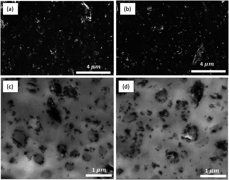
SEM images (Figure 2(a) and (b)) show well dispersed and distributed GNPs throughout the sample, together with some micron-sized aggregates. Overall, the GNPs appear well integrated within the polymer, showing good adhesion. Closer examination of the morphology of the TPO composites by TEM (Figure 2(c) and (d)), reveals a segregated morphology, demonstrating a typical droplet-matrix morphology containing dispersed droplets of EOC, within the PP matrix. The GNPs exhibit preferential partitioning at the interface and the dispersed EOC phase. Petrie et al. 20 reported that carbonaceous additives, such as multi-walled carbon nanotubes (MWCNTs), tend to localize preferentially in the dispersed phase of TPO blends. This is attributed to the fact that the EOC has lower melting point, and during melt compounding the fillers tend to be encapsulated within the EOC component, which melt first. However, in the presence of the PP-g-Py compatibilizer, there is a thermodynamic driving force for these fillers to migrate towards the interface and the PP phase during compounding.
Figure 2.
SEM (a and b) and TEM (c and d) images of compression molded TPO samples: PP-20EOC-15GNP (a and c) and PP-40EOC-15GNP (b and d).
This can be explained on the basis of the wetting coefficient (ω a ), which can be expressed in terms of the interfacial tensions between the various ternary blend components (γ i/j ), as shown in equation (1) 20 :
| (1) |
If > 1, the GNPs will distribute within the PP phase; if −1 < < 1, the GNPs will reside at the interface; if < −1, the GNPs are expected to distribute within the EOC phase.
The surface energy values of all the ternary blend components are summarized in Table 2.
Table 2.
Surface energy values (mJ/m2), including the total, γtotal, dispersive, γd and polar, γp components, estimated at 190°C.
aEstimated according to the data provided in Ref 20 , assuming 10 wt% PP-g-Py content in the PP.
The interfacial tension can be estimated from equation (2) below:
| (2) |
where the subscripts 1 and 2 stand for components 1 and 2 respectively.
Using the resulting values of γGNP/EOC = 6.9 mJ/m2, γGNP/PP = 6 mJ/m2, γPP/EOC = 0.73 mJ/m2, in equation (1) results in a partition coefficient of 1.2, indicative of the thermodynamic tendency for the GNPs to migrate from the EOC phase toward the interface, and eventually towards the PP at long compounding times. Since the process is controlled by kinetic considerations, maintaining a relatively short compounding time results in the GNPs residing mainly at the interface.
The presence of the GNPs at the interface stabilizes the morphology, and suppresses the coalescence of the dispersed phase at high concentrations. Therefore, the blends containing 40 wt% EOC maintain a fine droplet-matrix morphology, unlike in our previous work, which showed that the corresponding unfilled blends demonstrated increased coalescence and coarse morphology. 14
Given that the processability of the melt during MEX depends mainly on the rheological and thermal properties,14,21,22 this morphology dictates the processability of the blend during MEX. Given that MEX in the present work is driven by pneumatic pressure, high viscosities generally result in significant pressure drops, and low extrusion rates. The addition of fillers such as GNPs in PP generally causes significant increases in the viscosity above the rheological percolation threshold of about 10–17 vol% (corresponding to 20–31 wt%). 15 To avoid excessive viscosity increases, which would result in pressure drops that would exceed the capacity of the instrument, we have chosen a GNP content of 15 wt% which is below the percolation threshold.
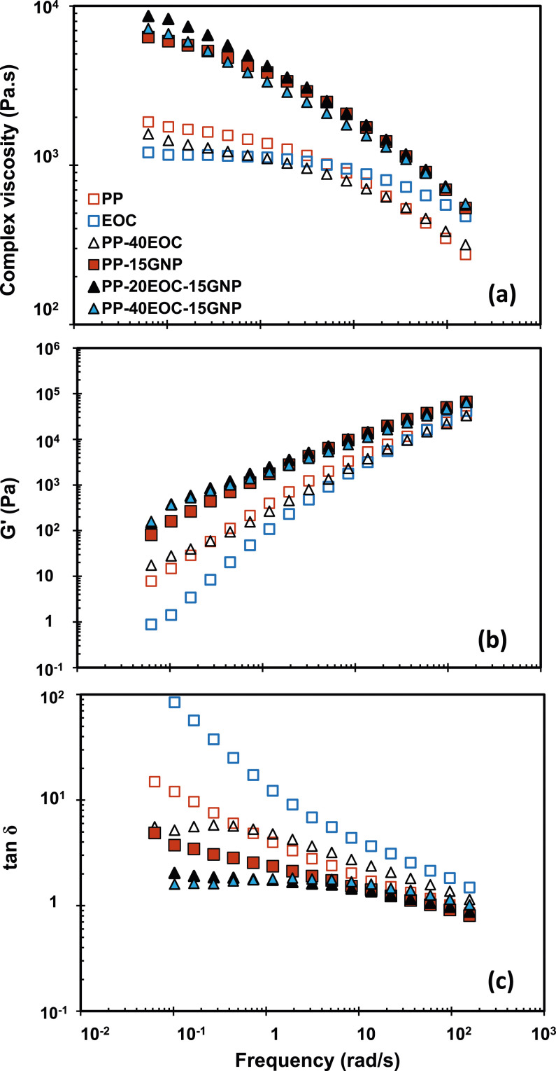
Furthermore, we decided on a PP with MFR of 12 to avoid excessive viscosity increases upon adding GNPs. The EOC grade was chosen to match the viscosity of the PP, as shown in the results of the frequency sweeps for PP, PP-GNP composites and blends, in Figure 3. In all cases, the addition of the GNPs increased the viscosity, however, a Newtonian plateau was still present, and the material preserved a viscoelastic liquid consistency, and shear thinning (Figure 3). Despite the significant increase in viscosity at low shear rates, the values in the shear rates that are relevant to the MEX processing (10–100 s−1) remained within acceptable limits for the operation of the instrument. 14
Figure 3.
(a) Complex viscosity, (b) storage modulus, (c) loss tangent at 210°C.
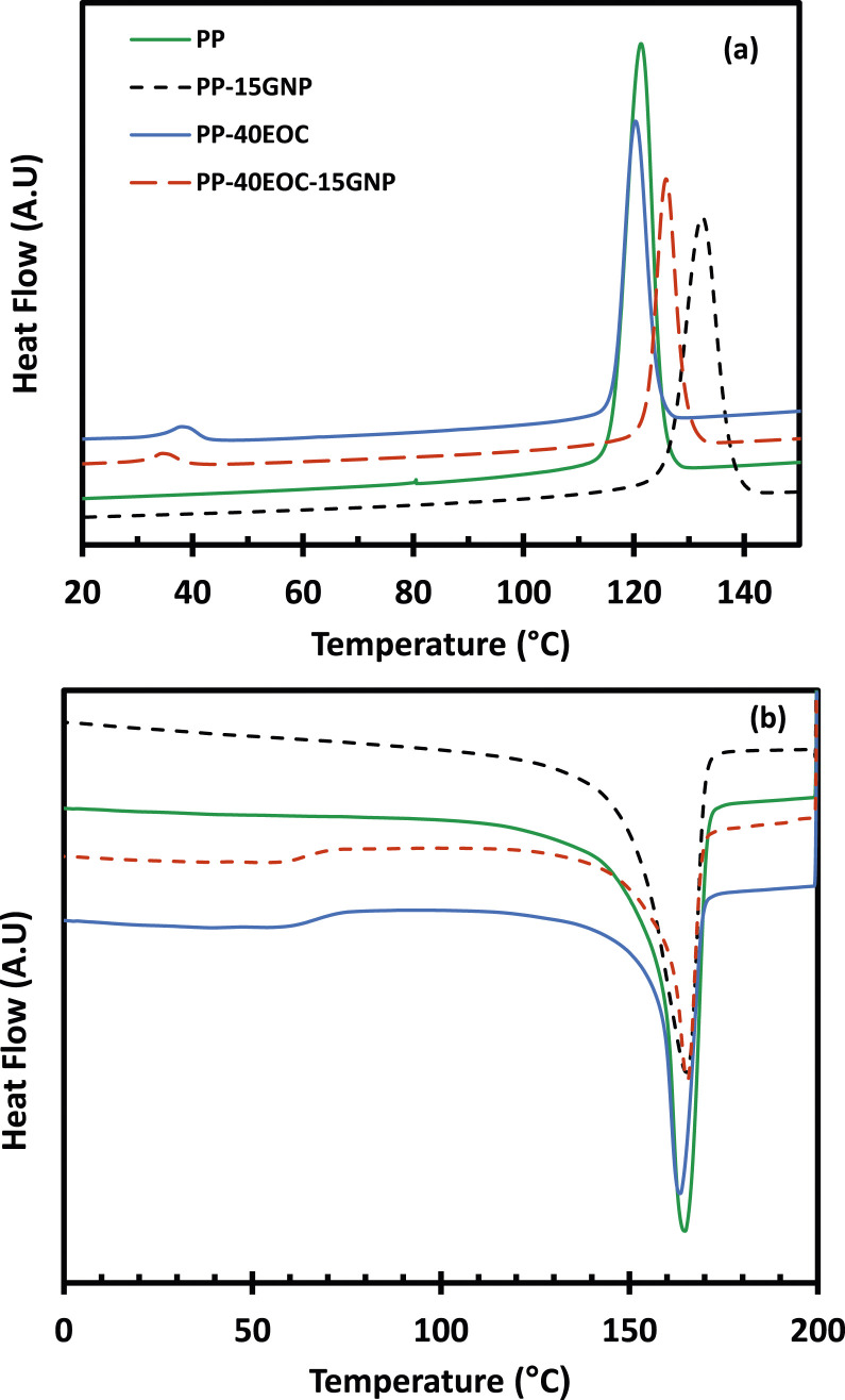
The presence of the low-crystallinity elastomeric EOC phase in the PP matrix is reflected in the DSC curves through the appearance of minor melting and crystallization peaks, as shown in Figure 4 and Table 3. Introduction of the GNPs in PP induced nucleation, resulting in higher crystallization temperatures. It is interesting to note that the shift is more significant in the PP-15GNP composites (a shift of 11°C), whereas it is smaller in the TPO composites (shifts of 5 and 6°C in PP-20EOC-15GNP and PP-40EOC-15GNP respectively). This is likely because in the TPO blends the GNPs are localized at the interface, therefore they do not affect as significantly the crystallization properties of the bulk PP phase.
Figure 4.
DSC curves of PP, TPOs and their composites with GNPs (a) cooling exotherm and (b) second heating endotherm.
Table 3.
Melting temperature (Tm) obtained from second heating endotherm and crystallization temperature (Tc) of the PP, TPO blends and composites.
| Sample | Tm, EOC (°C) | Tm, PP (°C) | Tc, EOC (°C) | Tc, PP (°C) |
|---|---|---|---|---|
| PP a | - | 164 | - | 122 |
| PP-15GNP | - | 165 | - | 133 |
| PP-20EOC | 60 | 165 | 34 | 119 |
| PP-20EOC-15GNP | 58 | 167 | 32 | 126 |
| PP-40EOC | 61 | 164 | 39 | 120 |
| PP-40EOC-15GNP | 59 | 165 | 36 | 126 |
aCorresponds to PP/PP-g-Py 90/10.
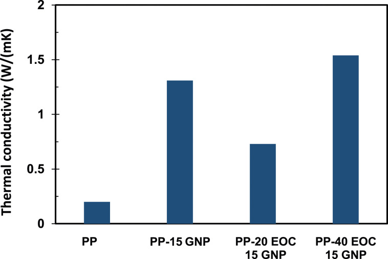
Even though these composites are below the electrical percolation threshold, 15 the composites exhibited a significant increase in their thermal conductivity, up to 1.3 W/m K for PP/GNP composites containing 15 wt% GNPs (Figure 5). The introduction of 20 wt% EOC reduced thermal conductivity to 0.73 W/(m K), presumably because the localization of the GNPs at the interface disrupted the conductive pathways. At 40 wt% EOC, there are more interfaces, given the higher amount of the dispersed EOC phase, which results in an increase of the thermal conductivity to 1.54 W/m K. These values are significantly higher than previous literature reports,23–25 and the reasons behind the mechanism of this increase merits further investigation in the future. Higher thermal conductivity may be beneficial, because it facilitates heat transfer between the phases during MEX processing.
Figure 5.
Comparison of thermal conductivity of PP and TPO composites.
Properties of Composites Processed by MEX
The addition of the GNPs is generally expected to have a reinforcement effect, thus improving the composites’ modulus.4,5,14,24,25 However, MEX differs from traditional processing methods, which produce solid parts, which have properties that are representative of the bulk material; depending on the degree of filling, 3D printed structures have voids, resulting in trapped air, and they frequently suffer from incomplete fusion between the deposited strands. The resulting interfaces and voids among layers become weak points, which can initiate cracks and result in premature breakage. 19
Furthermore, our previous work demonstrated that parts prepared by processing unfilled PP by MEX suffered from warpage, and strand debonding due to poor interfacial adhesion, which resulted from incomplete fusion between the strands. 14 These observations were attributed to the fast crystallization rate of PP that hindered the fusion between the printed strands.
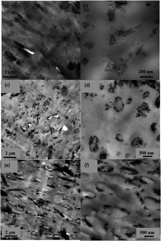
Using the PP-g-Py as a compatibilizer facilitates uniform dispersion of the GNPs within the PP matrix. 15 The GNPs, which were evenly distributed throughout the matrix of the 3D printed specimens (Figure 6(a) and (b)) induced nucleation, increased the crystallization temperature (see also Table 3), and thus further exacerbated the problem by accelerating the crystallization kinetics of PP. Fast solidification of the strands and higher viscosity prevented chain interdiffusion between the deposited strands and, therefore, had a detrimental effect on the interfacial fusion.
Figure 6.
TEM micrographs of composites processed by MEX (a and b) PP-15 GNP; (c and d) PP-20 EOC-15 GNP; (e and f) PP-40 EOC-15 GNP.
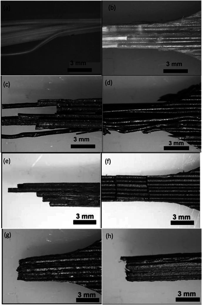
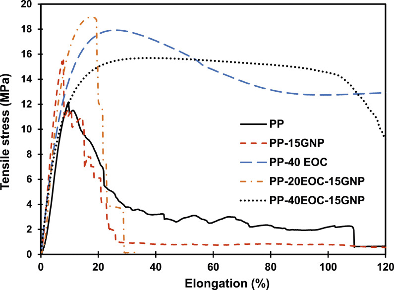
This effect can be demonstrated by examining images of the tensile test specimens after the completion of the test, obtained by using a stereomicroscope. Figures 7(a), (c) and (d) show severe strand delamination in PP and PP/GNP specimens, and adhesive failure between strands during the test, stemming from poor intralayer bonding (adhesion between strands). This caused a noisy step-wise decrease in the tensile stress curves (Figure 8), brittle fracture and extremely low elongation at break. For these samples, estimating the tensile properties becomes meaningless, and therefore we do not report them.
Figure 7.
Images of 3D printed tensile specimens obtained using a stereomicroscope (a) PP; (b) PP-40 EOC; (c and d) PP-15 GNP; (e and f) PP-20EOC-15GNP; (g and h) PP-40EOC-15GNP.
Figure 8.
Tensile stress versus strain curves of MEX printed specimens.
The positive effect of adding EOC can be seen by examining the behaviour of the TPO blends during tensile testing. The MEX-processed parts exhibited better intralayer and interlayer adhesion than the neat PP (Figure 7(b)). As demonstrated previously, 14 the EOC domains elongate towards the direction of the flow upon processing by MEX. These elongated EOC strands have lower crystallization temperature compared to the PP (see Table 3), and thus remain in the melt state longer, acting as an adhesive, and allowing for improved fusion between the extruded strands, and improved part consolidation (Figure 7(b)). The TPO samples show typical ductile behaviour, exhibiting yield stress during tensile testing (Figure 8), with elongations at break that are higher than 1500%.
Compared to the adhesive failure and strand delamination seen in PP-15GNP (Figure 7(c) and (d)), the TPO composites showed clearly improved strand consolidation, more uniform strand elongation and evidence of cohesive failure during the tensile tests. This is the result of better interfacial bonding in the presence of EOC (Figure 7(e)–(h)). The amount of EOC plays a role in the response during the tensile testing of the composites. Figure 6(c)–(g) show the EOC domains dispersed within the PP matrix in the 3D printed specimens. At 20 wt% EOC, the domains are small, and there is not enough EOC to influence interfacial bonding positively. The response during the tensile tests was still brittle, albeit improved compared to the PP/GNP composite (Figure 8), and there is evidence of the mechanism switching to cohesive failure, as shown in Figure 7(e)–(h).
Increasing the amount of EOC to 40 wt% increased the surface area of the elongated domains (Figure 6(e) and (f)), therefore ensuring better adhesion, and a more uniform response, demonstrating considerable ductility during the tensile test (Figure 8). Careful examination of the fracture surface shows some fibrils protruding from the fractured surface. The elongation at break increased from less than 10% in the PP-15GNP composite, to 20% for the PP-20EOC-15 GNP and 105% for the PP-40EOC-15GNP composites, while the modulus dropped, as expected in the presence of the softer EOC phase, from 3207 ± 902 MPa for PP-GNP to 2593 ± 529 MPa for PP-20EOC-15 GNP and 1524 ± 78 MPa for the PP-40EOC-15GNP composites. It is important to note, however, that given the nature of the MEX parts and the degree of inhomogeneity in the samples, it is impossible to extract useful information about the modulus using tensile tests.
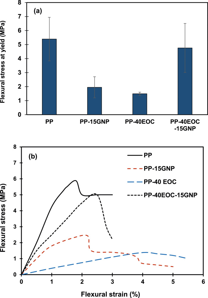
The flexural tests provide another means to not only assess the reinforcement potential of the GNPs in MEX-printed parts, but also to quantify the level of adhesion between strands. 19 For these tests, the printing pattern was chosen to be parallel to the direction of the force during the flexural test (see also Figure 1(b)), to better assess the extent of strand debonding during the test. The flexural stress at yield is reported in Figure 9, as in the present case we can assume that the yield point coincides with the point where the strands begin to be separated. As such, the flexural stress reported is lower than what would be reported for the corresponding bulk polymer, since the 3D printed specimens are not fully consolidated. As seen in Figure 9(a), the PP-GNP15 composite exhibits lower flexural strength than the neat PP. As explained earlier, this is attributed to the poor interfacial bonding, resulting in easy delamination of the strands and adhesive failure during the test. In the flexural test, the load is applied perpendicular to the print layers, creating stresses that cause layer delamination and premature adhesive failure in the PP-GNP15 composite parts, which are very poorly consolidated. This results in a noisy response, as shown in Figure 9(b). Therefore, this test does not represent the actual bulk strength of the composite, but rather it reflects the interfacial failure between strands.
Figure 9.
(a) Flexural stress at yield of PP and TPO composites prepared by MEX; (b) Flexural stress versus strain curves.
The PP-40 EOC blend had lower flexural stress than the neat PP, as expected, because of the addition of the softer EOC phase. In these blends, the introduction of GNPs increased the flexural stress, showing that the GNPs had the desired effect of reinforcing the blend. The fact that the flexural strength of the PP-40EOC-15GNP composite improved significantly, compared to the unfilled PP-40 EOC as shown in Figure 9, is attributed to the presence of the elongated EOC domains between the strands that facilitate their consolidation, while the GNPs reside at the interface (see also Figure 6(f)), providing a reinforcement effect. This demonstrates the beneficial effect of this segregated morphology in terms of strengthening the TPO matrix while maintaining good consolidation in the 3D-printed parts.
Conclusions
This study investigated the material extrusion of PP and TPO composites containing GNPs. Addition of 15 wt% GNPs to the PP increased the crystallization temperature and viscosity of the composite, compared to the neat PP. The printed strands exhibited poor interfacial adhesion, and the tensile and flexural specimens experienced brittle fracture and severe delamination. Blending of PP with an elastomeric impact modifier, EOC, resulted in TPO blends having droplet-matrix morphology at compositions up to 40 wt% EOC, with the GNPs localized mostly at the interface. The composites containing GNPs exhibited significant increases in the thermal conductivity with respect to the neat PP, with the highest increase, by 670%, corresponding to the PP-40EOC-15GNP composites. The EOC had lower crystallization temperature, and therefore remained in the melt state for longer time during the deposition process, following extrusion of the strands. This promoted significant improvements in the interfacial bonding, resulting in more consistent mechanical properties, improved ductility and flexural properties of the parts that were printed out of the TPO composites containing 40 wt% EOC, compared to the PP/GNP composites. We conclude that the segregated morphology, comprising high contents of a dispersed EOC elastomer and GNPs residing at the interface of the two blend components, promotes interfacial fusion between strands and part consolidation, leading to improved processability and structural integrity compared to the PP/GNP composites.
Acknowledgments
The authors gratefully acknowledge funding received from the Natural Sciences and Engineering Research Council of Canada (NSERC), MITACS and a Dean’s Research Fund from the Faculty of Engineering and Applied Science, Queen’s University.
Footnotes
The author(s) declared no potential conflicts of interest with respect to the research, authorship, and/or publication of this article.
Funding: The author(s) disclosed receipt of the following financial support for the research, authorship, and/or publication of this article: This work was supported by the Mitacs and Natural Sciences and Engineering Research Council of Canada.
ORCID iD
Marianna Kontopoulou https://orcid.org/0000-0002-0297-5966
References
- 1.Pereira T, Kennedy JV, Potgieter J. A comparison of traditional manufacturing vs additive manufacturing, the best method for the job. Procedia Manuf 2019; 30: 11–18. DOI: 10.1016/j.promfg.2019.02.003. [DOI] [Google Scholar]
- 2.Gnanasekaran K, Heijmans T, van Bennekom S, et al. 3D printing of CNT- and graphene-based conductive polymer nanocomposites by fused deposition modeling. Appl Mater Today 2017; 9: 21–28. DOI: 10.1016/j.apmt.2017.04.003. [DOI] [Google Scholar]
- 3.Xu W, Jambhulkar S, Ravichandran D, et al. 3D printing-enabled nanoparticle alignment: a review of mechanisms and applications. Small 2021; 17: 2100817. DOI: 10.1002/smll.202100817. [DOI] [PubMed] [Google Scholar]
- 4.Ozturk F, Cobanoglu M, Ece RE. Recent advancements in thermoplastic composite materials in aerospace industry. J Thermoplast Compos Mater In press. DOI: 10.1177/08927057231222820. [DOI]
- 5.Zhu D, Ren Y, Liao G, et al. Thermal and mechanical properties of polyamide 12/graphene nanoplatelets nanocomposites and parts fabricated by fused deposition modeling. J Appl Polym Sci 2017; 134: 1–13. DOI: 10.1002/app.45332. [DOI] [Google Scholar]
- 6.Mohan VB, Bhattacharyya D. Mechanical, electrical and thermal performance of hybrid polyethylene-graphene nanoplatelets-polypyrrole composites: a comparative analysis of 3D printed and compression molded samples. Polymer-Plastics Technology and Materials 2020; 59: 780–796. DOI: 10.1080/25740881.2019.1695272. [DOI] [Google Scholar]
- 7.Jia Y, He H, Geng Y, et al. High through-plane thermal conductivity of polymer based product with vertical alignment of graphite flakes achieved via 3D printing. Compos Sci Technol 2017; 145: 55–61. DOI: 10.1016/j.compscitech.2017.03.035. [DOI] [Google Scholar]
- 8.Mardlin K, Osazuwa O, Kontopoulou M, et al. Polyamide composites containing graphene nanoplatelets produced via thermomechanical exfoliation. Compos Sci Technol 2022; 225: 109493. DOI: 10.1016/j.compscitech.2022.109493. [DOI] [Google Scholar]
- 9.Wei X, Li D, Jiang W, et al. 3D printable graphene composite. Sci Rep 2015; 5: 1–7. DOI: 10.1038/srep11181. [DOI] [PMC free article] [PubMed] [Google Scholar]
- 10.Mishra V, Negi S, Kar S, et al. Recent advances in fused deposition modeling based additive manufacturing of thermoplastic composite structures: a review. J Thermoplast Compos Mater 2023; 36: 3094–3132. DOI: 10.1177/08927057221102857. [DOI] [Google Scholar]
- 11.Yang L, Chen Y, Wang M, et al. Fused deposition modeling 3D printing of novel poly(vinyl alcohol)/graphene nanocomposite with enhanced mechanical and electromagnetic interference shielding properties. Ind Eng Chem Res 2020; 59: 8066–8077. DOI: 10.1021/acs.iecr.0c00074. [DOI] [Google Scholar]
- 12.Camargo JC, Machado ÁR, Almeida EC, et al. Mechanical properties of PLA-graphene filament for FDM 3D printing. Int J Adv Manuf Technol 2019; 103: 2423–2443. DOI: 10.1007/s00170-019-03532-5. [DOI] [Google Scholar]
- 13.Guo H, Lv R, Bai S. Recent advances on 3D printing graphene-based composites. Nano Materials Science 2019; 1: 101–115. DOI: 10.1016/j.nanoms.2019.03.003. [DOI] [Google Scholar]
- 14.Ho QB, Kontopoulou M. Improving the adhesion and properties in the material extrusion of polypropylene by blending with a polyolefin elastomer. Addit Manuf 2022; 55: 102818. DOI: 10.1016/j.addma.2022.102818. [DOI] [Google Scholar]
- 15.Ho QB, Kontopoulou M. Compatibilized polypropylene nanocomposites containing expanded graphite and graphene nanoplatelets. Polym Eng Sci 2021; 61: 1116–1128. DOI: 10.1002/pen.25647. [DOI] [Google Scholar]
- 16.Kontopoulou M, Wang W, Gopakumar TG, et al. Effect of composition and comonomer type on the rheology, morphology and properties of ethylene-α-olefin copolymer/polypropylene blends. Polymer (Guildf) 2003; 44: 7495–7504. DOI: 10.1016/j.polymer.2003.08.043. [DOI] [Google Scholar]
- 17.Mardlin K, Osazuwa O, Kontopoulou M. Solvent-free thermomechanical exfoliation of graphite into graphene nanoplatelet flakes: implications for conductive composites. ACS Appl Nano Mater 2022; 5: 4938–4947. DOI: 10.1021/acsanm.1c04517. [DOI] [Google Scholar]
- 18.ASTM International . Standard test method for flexural strength of adhesive bonded laminated. West Conshohocken: ASTM, 2020. DOI: 10.1520/D1184-98R20.1. [DOI] [Google Scholar]
- 19.Wang L, Gardner DJ. Contribution of printing parameters to the interfacial strength of polylactic acid (PLA) in material extrusion additive manufacturing. Prog Addit Manuf 2018; 3: 165–171. DOI: 10.1007/s40964-018-0041-7. [DOI] [Google Scholar]
- 20.Petrie KG, Osazuwa O, Docoslis A, et al. Controlling MWCNT partitioning and electrical conductivity in melt compounded polypropylene/poly(ethylene-co-octene) blends. Polymer (Guildf) 2017; 114: 231–241. DOI: 10.1016/j.polymer.2017.02.087. [DOI] [Google Scholar]
- 21.Gopi S, Kontopoulou M. Investigation of thermoplastic melt flow and dimensionless groups in 3D bioplotting. Rheol Acta 2020; 59: 83–93. DOI: 10.1007/s00397-019-01186-4. [DOI] [Google Scholar]
- 22.Gopi S, Ramsay BA, Ramsay JA, et al. Preparation, characterization and processing of PCL/PHO blends by 3D bioplotting. Int Polym Process 2020; 35: 458–470. DOI: 10.3139/217.3971. [DOI] [Google Scholar]
- 23.Krause B, Rzeczkowski P, Pötschke P. Thermal conductivity and electrical resistivity of melt-mixed polypropylene composites containing mixtures of carbon-based fillers. Polymers 2019; 11: 1073. DOI: 10.3390/POLYM11061073. [DOI] [PMC free article] [PubMed] [Google Scholar]
- 24.Krause B, Pötschke P. Electrical and thermal conductivity of polypropylene filled with combinations of carbon fillers. AIP Conf Proc 2016; 1779: 1–6. DOI: 10.1063/1.4965494. [DOI] [Google Scholar]
- 25.Chen RS, Mohd Ruf MFH, Shahdan D, et al. Enhanced mechanical and thermal properties of electrically conductive TPNR/GNP nanocomposites assisted with ultrasonication. PLoS One 2019; 14: 1–16. DOI: 10.1371/journal.pone.0222662. [DOI] [PMC free article] [PubMed] [Google Scholar]


