Abstract
The integrity of dissimilar Al-Ti welds during conventional friction stir welding (CFSW) is compromised by excessive material mixing, leading to thick intermetallic layers. Underwater friction stir welding (UWFSW) mitigates these effects by inhibiting material mixing due to lower thermal conditions. Scanning electron microscopy revealed substantial Ti particles, appearing as blocks and strips, within the stir zone during CFSW. Static recrystallization, driven by exothermic reactions between Ti blocks and the Al matrix, resulted in over 93% recrystallized grains along stir zone, 10.7% higher than in UWFSW. In contrast, UWFSW resulted in a finer dispersion of Ti particles with reduced density due to lower frictional heat. The average grain size at the Ti interface of CFSW was 1.0 μm, compared to 2.6 μm in UWFSW. The inhomogeneous distribution of Ti particles in CFSW led to uneven dislocation distribution and increased stress concentrations, while finer Ti particles in UWFSW promoted a uniform grain structure, enhancing joint strength to 267 MPa, 13.4% higher than CFSW. Additionally, the γ-fibre and basal fibre texture in UWFSW increased joint ductility. The study highlights UWFSW’s effectiveness in joining dissimilar metals, offering significant advantages for industries such as aerospace and automotive.
Keywords: Submerged FSW, Dissimilar materials, Microstructure evolution, Texture analysis, Mechanical properties
Subject terms: Mechanical engineering, Materials science
Introduction
Joining dissimilar materials has become an increasingly important area of research in recent years as the demand for lightweight and high-performance materials continues to grow. This is especially true in industries such as aerospace, automotive, and biomedical, where the need for unique material properties has prompted the use of combinations like, magnesium-titanium, aluminum-magnesium, aluminum-titanium, aluminum-steel, magnesium-steel, and aluminum-copper. For instance, in the aerospace industry, landing gear components often incorporate both aluminum and titanium to achieve a balance of strength, durability, and lightweight design. However, joining Al to Ti is particularly challenging because of the disparities in their chemical, mechanical and physical properties, which can lead to residual stresses and distortion in the joint1. Moreover, the formation of brittle intermetallic compounds (IMCs) during welding can reduce the strength and durability of the joint. This, in turn, may compromise the quality and consistency of the joint and potentially lead to premature failure2. Therefore, the development of reliable and efficient methods for joining dissimilar Al to Ti is crucial for the advancement of these industries.
Numerous research has suggested that solid-state welding techniques, such as friction stir welding (FSW), are highly effective for joining dissimilar metals such as Al and Ti3,4. Consequently, there have been many investigations on the dissimilar joining of Al to Ti using FSW, with a focus on optimizing process parameters5. Taher et al.6 observed that increasing the rotational speed during FSW of Al to Ti activates the superplastic deformation of the Al-Ti intermetallic phase, leading to the thickening of the intermetallic layer. Similarly, Kumar et al.7 noted that raising the peak temperature results in a more diffusive reaction, resulting in the formation of thick intermetallic layers. Previous research by Hou et al.8 and Song et al.9 demonstrated that offsetting the welding tool on the Al matrix can reduce material flow; however, this approach alone does not fully mitigate the detrimental effects of IMCs. For instance, Sundar et al.10 observed that even with a 2 mm offset while joining Al6061 to Ti6Al4V, Ti layers were still present at the interface. This was attributed to the shoulder’s rotational action, which continued to engage the Ti layers actively. Additionally, the lower melting point of Al compared to Ti causes premature softening of aluminum, resulting in voids, cracks, and flash defects in the weld nugget. The literature clearly indicates that the formation of IMCs significantly impacts the strength and other mechanical properties of weldments. A study by Kim et al.11, found that mechanical properties degrade when the IMC layer thickness exceeds 5 μm. Therefore, it is essential to choose process conditions that prevent the formation of a continuous, thick IMC layer to avoid detrimental effects on the interfacial microstructure.
Underwater Friction Stir Welding (UWFSW) is an adaptation of FSW that employs water as a cooling medium to regulate temperature profiles and reduce the peak weld temperature12. By immersing the base materials in a water-filled container or applying a constant water flow, UWFSW creates a controlled thermal environment that enhances mechanical properties3,13. According to Papahn et al.14, the thermal cycle in UWFSW shows a peak temperature reduction of about 40% compared to conventional FSW (CFSW). This water circulation technique effectively lowers welding temperatures, resulting in decreased heat input in UWFSW, which in turn leads to finer grain structures and smaller precipitates that enhance the strength and other physical properties of the weld joint. Derazkola et al.15 successfully joined AA5083 alloy and A441 AISI steel, employing underwater cooling mediums at temperatures of 0, 25, and 50 °C, in conjunction with ambient air processing. They observed an outstanding combination of tensile strength and elongation, achieving a maximum joint strength ratio of around 97%. Importantly, several researchers16–18 have substantiated that immersing the dissimilar joint in lower-temperature water plays a pivotal role in decreasing the peak temperatures during FSW. Consequently, this practice effectively mitigates undesirable effects such as metal intermixing, grain coarsening, and the formation of IMCs19. Lader et al.20 used UWFSW to join aluminium to brass and observed a 68.86% reduction in weld temperature compared to CFSW. This substantial reduction in temperature led to the formation of finer recrystallized grains and an increased proportion of high-angle grain boundaries. Additionally, UWFSW effectively suppresses the formation of IMCs, thereby improving the hardness and strength of the weldment21. Similarly, Mao et al.22 found that UWFSW of Al to Cu reduced the IMC layer thickness, leading to a 41.7% increase in tensile strength compared to weldments produced by CFSW. However, previous investigations have not focused on the significance of UWFSW when applied to different material combinations, and there is no prior research on UWFSW of Al to Ti.
Consequently, our study employs UWFSW to effectively join Al and Ti, aiming to significantly reduce material mixing and welding heat input. By conducting comprehensive analyses including temperature measurements, interface reactions, and interface microstructure, this research article elucidate the mechanisms that enhance the microstructural and mechanical properties of dissimilar Al-Ti joints. Our findings are expected to highlight the advantages of UWFSW in producing superior weld quality, characterized by finer grain structures, reduced IMC layer thickness, and improved tensile strength, thereby offering valuable insights for industrial applications where dissimilar metal joining is crucial.
Methods and materials
In this investigation, plates of Al6061-T6 and Ti6Al4V were subjected to CFSW and UWFSW with process parameters described in Table 1, according to the joint detailed in Fig. 1. For underwater welding setup, still water was used to create a stable thermal environment. This approach was chosen to avoid the potential variability introduced by flowing water. For precise temperature monitoring during welding, three K-type thermocouples were placed at 15, 20 and 25 mm from the abutting edges on the Al side, as shown in Fig. 1a and b. The Al6061-T6 plate was placed on the advancing side, and the Ti6Al4V plate was positioned on the retreating side to optimize material flow during the welding process. The detailed tool description of the tapered tool along with the dimensions are given in Fig. 1c. Upon welding, the samples were sectioned transversely with a wire cut EDM machine for detailed analysis. Macrostructural features were studied using an optical microscope and field emission scanning electron microscope (Fe-SEM) equipped with energy-dispersive spectroscopy (EDS) for elemental analysis. Microstructural changes along the weldment were examined using electron backscatter diffraction (EBSD). Interfacial characteristics were assessed through X-ray diffraction (XRD) analysis. Vickers microhardness test was conducted in accordance with ASTM E384 standards, and tensile strength assessments were conducted on a universal tensile testing machine at room temperature, as outlined in ASTM E8 guidelines.
Table 1.
Process parameters used to weld Al6061 to Ti6Al4V by UWFSW & CFSW.
| Process parameters | CFSW10 | UWFSW |
|---|---|---|
| Rotational speed(rpm) | 1200 | 1200 |
| Feed rate(mm/min) | 45 | 45 |
| Tool offset (mm) | 2 (on Al side) | 2 (on Al side) |
| Tilt angle (°) | ≈ 1 | ≈ 1.5 |
| Plunge depth (mm) | 0.2 | 0.2 |
Fig. 1.
Joint configuration used in this study: (a) CFSW and (b) UWFSW; (c) Schematic of FSW tool used in the study.
Results and discussions
Weld formation
Figure 2 illustrates the cross-sectional macrostructures of joints welded through CFSW (Fig. 2a) and UWFSW (Fig. 2b) under optimal process conditions, both exhibiting a lamellar flow pattern near the Ti interface. During FSW, the tool plunges into the abutting edges of the base materials, with the pin entering first, followed by the shoulder. This contact generates significant heat, causing plasticization of the surrounding material. However, the thermal conditions achieved in this study were insufficient to induce plastic deformation in Ti, as its yield strength at the examined temperature range is approximately 353MPa23. Under these conditions, Ti experiences higher strain rates at low homologous temperatures. During FSW, Al reaches a fully plasticized state, and the deformed Ti layer near the interface breaks down under the pressure applied by the tool shoulder, causing it to adhere to the pin surface. As the tool progresses, the plasticized aluminium at the leading edge is moved to the trailing edge, bringing the adhered Ti with it. With continued transverse movement of the tool, the heat intensity decreases, resulting in the shearing of the adhered material just behind the tool, leading to the formation of lamellae at the Ti Interface. In CFSW welds, the lamellar flow pattern is characterized by Ti strips (Fig. 2c), whereas in UWFSW, it consists of smaller Ti particles, as highlighted in Fig. 2d. This distinction is due to the lower temperatures generated during UWFSW, which result in less interaction and material flow of Ti, leading to a finer dispersion of Ti particles compared to the larger Ti strips formed during CFSW.
Fig. 2.
(a) Optical macrostructure of CFSW joint10, (b) Optical microstructure of UWFSW joint42, (c) Fe-SEM micrographs of CFSW joint at Ti-interface42 and (d) Fe-SEM micrographs of UWFSW joint at Ti interface.
The dispersed Ti particles within the Al matrix contribute to additional deformation resistance, thereby impeding the movement of dislocations induced by the tool. As a result, the finer Ti particles in UWFSW are less effective in impeding dislocation movement compared to the larger Ti particles in CFSW, leading to higher plastic deformation and strain in UWFSW joints. Closer examination of the Fe-SEM micrographs reveals that the size of Ti particles decreases progressively from the advancing side towards the centre of the stir zone (CSZ). This phenomenon can be attributed to continuous deformation and further fragmentation of larger Ti strips initially present near the Ti interface. During the processes of fragmentation and material flow, the softened Al flows all through the stir zone (SZ), leading to the creation of a hook-like structure at Al interface, as shown in Fig. 2a and b. This interlocking structure serves as a bonding mechanism between the two dissimilar materials.
Thermal history and intermetallic formation
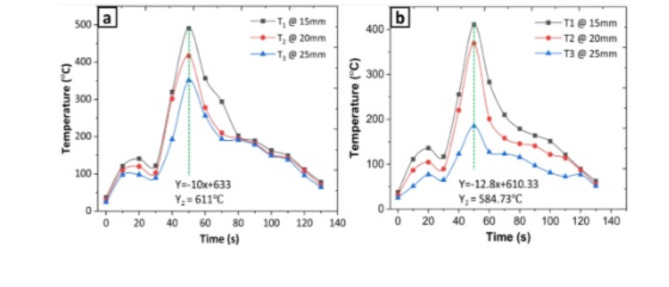
The temperature profiles for UWFSW and CFSW were recorded and compared, as shown in the Fig. 3. The welding process started at an initial temperature of 28.4℃ (room temperature), with the tool dwelling for 60 s. During this dwell period, a moderate increase in temperature was detected by all thermocouples for both welding conditions. In UWFSW (Fig. 3b), the recorded temperatures at thermocouples (T1, T2, and T3) were 473, 391, and 347℃, respectively. In contrast, the CFSW (Fig. 3a) recorded temperatures were 481, 407, and 381℃ at the same thermocouples. By estimating the linear extrapolation of the slope between peak temperature and offset of 2 mm from the frayed surface, the weld temperatures were predicted as 584℃ for UWFSW and 611℃ for CFSW. The higher temperatures observed in CFSW are due to the increased frictional heat produced during the process. In contrast, UWFSW effectively mitigates this heat with circulating water. The lower welding temperatures in UWFSW result from the water’s higher specific heat capacity and convective heat transfer coefficient, which allow it to absorb heat more efficiently. This efficient heat absorption not only limits the peak temperature but also promotes a more controlled and uniform temperature distribution, thereby improving material flow characteristics.
Fig. 3.
(a) Temperature distribution profile of CFSW and (b) Temperature distribution profile of UWFSW.
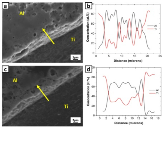
To investigate the elemental diffusion behaviour at the interface, an EDS line scan and the elemental mapping were plotted for the weldments under both conditions. The EDS line scanning direction was from unreacted Ti to unreacted Al, as shown in the Fig. 4a and c. The concentration gradients of Al and Ti exhibited unsteady upward and downward trends in both CFSW (Fig. 4b) and UWFSW (Fig. 4d), indicating a complex interface reaction with the presence of numerous Ti strips and particles. It is important to note that the elemental diffusion distance in CFSW is much larger than that in the UWFSW joint. At elevated temperatures, the diffusion rates of Al and Ti are significantly increased, facilitating more extensive interdiffusion of these elements across the interface. This elevated atomic mobility reduces the activation energy required for diffusion, thereby accelerating the growth of IMCs24. Additionally, the exothermic reactions between Al and Ti generate further thermal energy, which enhances the reaction kinetics and promotes the formation of a thicker IMC layer. Consequently, the combination of higher thermal input and, enhanced atomic diffusion results in the formation of a substantially thicker IMC layer in CFSW compared to UWFSW, where the cooling effect of water limits the thermal input and thus the extent of interdiffusion.
Fig. 4.
(a) Fe-SEM micrographs at the Ti interface of CFSW, (b) EDS line scan analysis at Ti interface of CFSW, (c) Fe-SEM micrographs at the Ti interface of UWFSW, and (d) EDS line scan analysis at Ti interface of UWFSW.
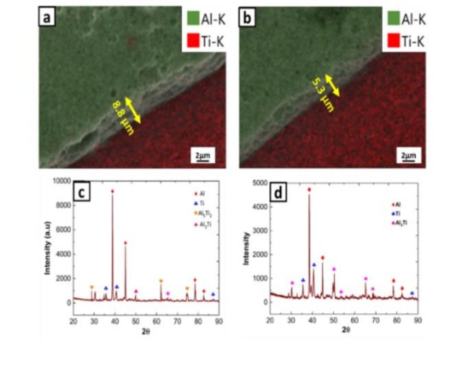
To verify the composition of IMCs, XRD analysis was performed at the interface, with results shown in Fig. 5c and d. The XRD patterns for both UWFSW and CFSW indicated the occurrence of Al, Ti, Al5Ti2 and Al3Ti. According to the reports by Kattner et al.25, five stable equilibrium phases occur from Al-Ti binary system: Ti3Al, AlTi, Al3Ti, Al2Ti, Al5Ti2. Among these intermetallic phases, Ti3Al, AlTi, Al3Ti can form by the reactions involving solid Ti and solid Al as starting phases and Al2Ti, Al5Ti2 can form by a series of reactions occurring with AlTi as starting phase26,27. Generally, the atomic interactions between two materials depend on Gibb’s free energy of formation. Based on the study by Sujatha et al.28, the Gibbs free energy of formation for these IMCs was calculated for the temperatures observed in our study, 584 °C and 611 °C, and is presented in the Table 2.
Fig. 5.
Fe-SEM elemental mapping at Ti interface: (a) CFSW, (b) UWFSW and XRD phase analysis results at Ti interface: (c) UWFSW, (d) CWFSW.
Table 2.
Temperature dependence of free energy of formation of various Ti-Al compounds and their values at process temperatures.
| Compounds | Gibbs free energy of formation (ΔGf) (J/mole) |
(ΔGf) 857 K (J/mole) |
(ΔGf) 884 K (J/mole) |
|---|---|---|---|
| Ti3Al | -29,633 + 6.708T | -23,884.244 | -23703.128 |
| TiAl | -37,445 + 16.793T | -23,053.399 | -22,599.988 |
| Al2Ti | -40,349 + 10.365T | -31,466.195 | -31,186.34 |
| Al3Ti | -43,858 + 11.021T | -34,413.515 | -34,115.436 |
| Al5Ti2 | -40,495 + 9.529T | -32,328.647 | -32,071.364 |
Among these phases, Al3Ti exhibits the lowest Gibbs free energy of formation at both 584 °C and 611 °C, making it the most thermodynamically favourable phase to form under the conditions studied in both CFSW and UWFSW. The formation of Al3Ti is facilitated by the interdiffusion of Al and Ti atoms, a temperature-dependent process driven by exothermic chemical reactions occurring around 600 °C. Although Al3Ti was expected to form based on the lowest Gibbs free energy, the XRD plots of UWFSW revealed the occurrence of Al5Ti2. This can be attributed to local compositional variations and temperature gradients induced by the stirring action during the welding process, which promote the formation of additional intermetallic phases like Al5Ti2.
The interface exhibited a clear transition, with differences in the width of the transition layers between CFSW (Fig. 5a) and UWFSW (Fig. 5b). CFSW exhibited a thicker layer of 8.8 μm, while UWFSW showed a comparatively thinner layer of 5.3 μm. The increased IMC layer thickness in CFSW is due to higher temperatures and enhanced frictional heat generated during the process. The thermal environment during welding significantly influences the thickness of the IMC layer. In UWFSW, the circulating water effectively reduces the peak welding temperature, leading to a thinner IMC layer compared to CFSW. This reduction in IMC layer thickness is beneficial because excessive growth of IMCs, particularly beyond 5 μm, can significantly degrade the mechanical properties of the weld due to increased brittleness. Therefore, although the predominant type of IMC formed remains the same, UWFSW resulted in a thinner IMC layer compared to CFSW, highlighting the significance of UWFSW in controlling IMC formation for improved weld performance.
Grain morphology and recrystallization behavior
At Ti interface
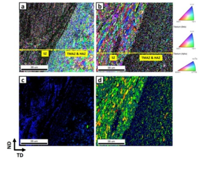
Zhao et al.29, highlighted the importance of both interface metallurgical bonding and material mixing in achieving successful dissimilar welds. Accordingly, a detailed analysis was conducted using EBSD at the Ti interface of the welds. The Fig. 6a and b illustrates the IPF map at the Ti interface of both CFSW and UWFSW, clearly showing the transition from the SZ to the heat affected zone (HAZ). In both cases, the grains closer to the HAZ maintained the same primitive rolling orientation of < 10 0>//TD, while the grains closer to the SZ were rotated to < 2
 0>//TD. The slight change in orientation of the base Ti6Al4V grains near the SZ is attributed to low thermo-mechanical coupling under the shear action of the pin, whereas the grains near the HAZ retained the same orientation as the base Ti6Al4V due to being subjected only to the welding thermal cycle rather than the stirring action of the tool. At InterfaceUWFSW, the average grain size was 2.6 μm, which decreased to 1.0 μm at InterfaceCFSW, despite the fact that the heat generated during UWFSW was comparatively lower than in CFSW. Furthermore, the grain orientation spread (GOS) revealed that 91.2% and 83.9% of the grains were completely recrystallized in CFSW and UWFSW, respectively, as shown in Fig. 6c and d. Interestingly, these results contradict previous literature on submerged FSW, which reported a reduction in grain size during UWFSW. The mechanisms leading to these results are explained below.
Fig. 6.
IPF map at Ti interface of (a) CFSW10, (b) UWFSW42; GOS map at Ti interface of (c) CFSW10, (d) UWFSW.
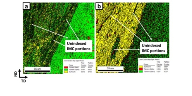
The phase map, as shown in Fig. 7, illustrates the presence of Al in yellow and Ti in green, while the black spots represent unindexed areas that are believed to be IMCs. As observed in the Fig. 7a, a higher number of black spots are seen in CFSW, indicating a greater formation of IMCs. Additionally, it is important to note from the phase map that in CFSW welds, long Ti strips (green strips) are present near the interface, whereas during UWFSW, these strips disappear, and small Ti particles are observed. This suggests that Ti offers greater resistance to shear deformation during UWFSW, which minimizes material flow near the interface.
Fig. 7.
EBSD phase map at Ti interface of (a) CFSW10 and (b) UWFSW.
Upon closer examination of the GOS maps, it was observed that the grains near the black spots, believed to be IMCs, were fully recrystallized. The formation of IMCs can lead to localized heating and an increase in temperature in the surrounding area, resulting in material softening and increased plasticity, which can facilitate static recrystallization. The plastic deformation of the material near the intermetallic layers generates dislocations, further promoting the formation of new recrystallized grains. The combination of these effects results in a higher percentage of recrystallized grains near the intermetallic layers. This process of static recrystallization predominates in areas near the interface, and since UWFSW inhibits material flow and intermetallic formation, the percentage of recrystallized grains in UWFSW is comparatively lower than in CFSW. This indicates that the rate of recrystallization during the joining of highly dissimilar Al to Ti is influenced by the extent of static recrystallization promoted by intermetallic formation.
At stir zone
The figure shows the IPF map at CSZ of CFSW and UWFSW, where the primitive orientation of the grains was completely replaced by equiaxed grains with the majority of them oriented along < 001>//TD in both cases, as shown in the Fig. 8a and b. The average grain size at CSZCFSW and CSZUWFSW dropped down to 0.6 μm and 1.4 μm, respectively, and their corresponding GOS map (Fig. 8c and d) showing 77% and 87% as recrystallized grains. The continuous deformation and fragmentation of larger Ti strips/blocks near the Ti interface result in a composite structure in the CSZ, where the Ti particles act as reinforcements over the Al matrix. These Ti particles serve as nuclei for particle-stimulated nucleation (PSN), and hinder the growth of existing grains by acting as physical barriers, resulting in a reduced grain size in the CSZ. As the tool traverses over the Ti particles, it initiates plastic deformation and induces a localized temperature rise through contact with the particles30. This interaction between the particle and the tool leads to increased temperature and pressure in the vicinity of the particle. The elevated temperature and pressure facilitate the formation of a molten zone, which, in turn, promotes the nucleation of new grains31. The presence of finer Ti particles in UWFSW provides more nucleation sites, leading to a higher nucleation density and smaller grain size. Conversely, as the particle size increases, the grain-refining effect diminishes, resulting in coarser grains in CFSW. Consequently, UWFSW accommodates more recrystallization due to PSN, contributing to the observed differences in microstructure between CFSW and UWFSW.
Fig. 8.
IPF map at centre of SZ of (a) CFSW10, (b) UWFSW; GOS map at centre of SZ (c) CFSW10, (d) UWFSW.
The complex action of the tool causes the material to experience a combination of stretching, compression, and torsion, which leads to the generation of lattice defects such as dislocations32. As the tool continuously deforms the material, the number of dislocations increases, consequently elevating the dislocation density33. In the case of Al, which possesses a high stacking fault energy, the accumulating dislocations begin to reorganize through the slip-and-climb mechanism34. During the subsequent cooling stages of FSW, these dislocations are absorbed by the grain boundaries, leading to the formation of dislocation-free recrystallized grains. Following this phase, the weld pool gradually cools down in an attempt to attain the annealing temperature specific to Aluminium35. However, due to the higher temperature and prolonged thermal exposure time in CFSW compared to UWFSW, it takes more time for CFSW to reach the annealing temperature. Consequently, a greater number of dislocations are absorbed during this extended period in CFSW. This phenomenon results in the conversion of previously recrystallized grains back into deformed grains, indicating a significant grain growth occurrence within the CFSW microstructure.
Texture development
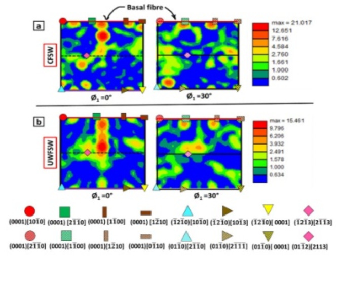
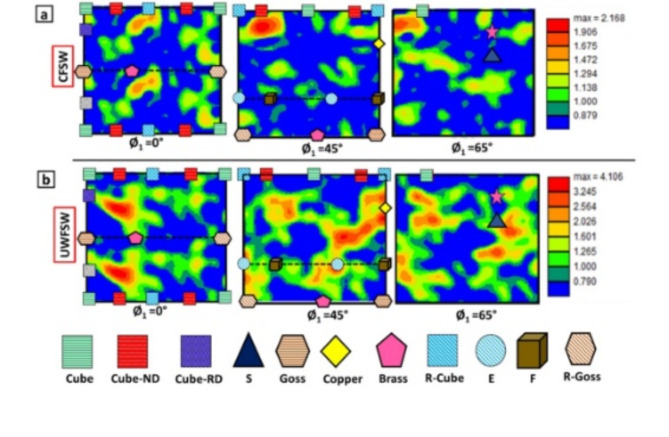
During FSW, three important texture components such as shear, deformation and recrystallization are formed in the weld affected region which plays an important role in determining the mechanical properties of the weld. For instance, the shear components provide high strength and ductility while other components affect the formability and anisotropy of the weld. So, in this study, for better interpretation of the various texture components formed, orientation distribution function (ODF) has been plotted at three Euler angles (Ø =0°, 45°, 65°) for Al6061 and at two Euler angles (Ø =0°, 30°) for Ti6Al4V. The obtained ODF maps at Ti-interface and CSZ has been overlapped in with ideal ODFs and the results are in the Figs. 9 and 10 respectively.
Fig. 9.
ODF maps of Ti6Al4V at Ti interface of: (a) CFSW and (b) UWFSW.
Fig. 10.
ODF maps of Al6061 at SZ of: (a) CFSW and (b) UWFSW.
Figure 9 depicts the ODF maps, superimposed with ideal maps for both InterfaceCFSW (Fig. 9a) and InterfaceUWFSW (Fig. 9b). At the InterfaceUWFSW, Ti6Al4V displays weak presence of (0001) [2 0], (0001) [1
 00] and (0001) [0
 10] with maximum intensity of 15.4. The formation of weak basal texture indicates the reduced degree of recrystallization. As previously discussed in the microstructure section, the reduced material flow near interface of UWFSW contributed less Ti particles and intermetallics, which directly reduced the occurrence of recrystallization due to PSN and SRX. The evolution of Ti6Al4V texture in InterfaceCFSW is completely different from the that of InterfaceUWFSW as shown in the Fig. 10b. Ti6Al4V develops a dominant basal texture, such as (0001) [1
 10] and (0001) [2
 0], reaching a peak intensity of 21.1. This basal texture formation in hexagonal closely packed materials is primarily due to the recrystallization of Ti, which is facilitated by the easy slip of dislocations on the basal plane36,37.
The CSZ of both the conditions mainly composed of recrystallization textures as shown in Fig. 10. CSZUWFSW (Fig. 11b) exhibited Cube-ND {001} <310>, Cube {001} <100 > and Cube-RD {013} <100 > components complemented by the significant presence of shear components such as {111} <110>, {111} <112>, and R- Goss {110} <110>. The development of equiaxed grains at the CSZ completely replace the initial grain growth direction and significantly reduce the texture intensity to 4.1. The development of strong recrystallization components can be attributed to occurrence of PSN. The generation of heat and plastic deformation through stirring pins results in the formation of recrystallization nuclei around Ti particles, leading to the development of recrystallization textures. It has to be noted that intense γ-fibre is observed at CSZUWFSW, indicating the improved formability of the UWFSW-ed Al-Ti joints. The texture obtained at CSZCFSW (Fig. 10a) appears to be random, with significant presence of R-cube {001} <110 > component at intensity of 2.1. The weaking of texture at CSZCFSW is due to complex material flow at high temperatures closer to melting point of Al. The random distribution of Ti particles in varying sizes at CSZCFSW contributed to the inhomogeneity, leading to random distribution of texture.
Fig. 11.
Microhardness distribution map of both CFSW and UWFSW.
Influence of UWFSW on mechanical properties
Microhardness distribution
The microhardness distribution profile of both UWFSW and CFSW is presented in the Fig. 11. The hardness test was conducted at three different layers (top, middle, bottom) along the transverse section of the weld, and the average values were used to plot the distribution profile. Al6061 and Ti6Al4V exhibited typical microhardness values of 98 HV and 334 HV, respectively. In the weld regions, hardness values remained below these baselines, largely because of the dissolution of strengthening precipitates and the formation of IMCs during FSW process38. It is notable that the range between minimum and maximum hardness values was narrower in UWFSW compared to CFSW. The increased hardness in the SZ of UWFSW is attributed to its uniform grain structure and the presence of small Ti particles. On the other hand, CFSW exhibited lower hardness, primarily due to the existence of intercalated IMC particles.
A notable decrease in hardness was observed at the transition from the Ti interface to SZ is observed at both conditions. The Ti interface is characterized by the presence of IMCs with a maximum microhardness of 332 HV and 319 HV for UWFSW and CFSW respectively. This is because the specific IMC Al3Ti, formed during FSW, is reported to have a higher hardness value26. Conversely, the Al interface displayed lower hardness than the base metals, a consequence of precipitate dissolution and grain coarsening induced by the welding thermal cycle. Overall, UWFSW demonstrated uniform microhardness distribution due to the presence of fewer hard intermetallics and the presence of fine Ti particles in the weld region, indicating a more homogeneous microstructure within the SZ.
Cross tensile test
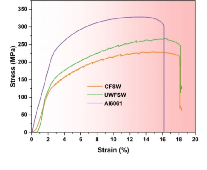
Tensile tests were conducted for both CFSW and UWFSW, with the findings and fracture locations for each condition detailed in Fig. 12; Table 3, respectively. The tensile strength achieved for CFSW and UWFSW were 267 MPa and 231 MPa respectively.
Fig. 12.
Stress Vs Strain Tensile plots under different conditions.
Table 3.
Summary of tensile test results.
| Tool Offset condition (mm on Al side) | UTS (MPa) | % Elongation | UTS of as- received Al6061 (MPa) | Failure Zone |
|---|---|---|---|---|
| UWFSW | 267 | 15.6 ± 0.7 | 328.4 | Weld nugget |
| CFSW | 231 | 7.7 ± 0.2 | Weld Interface |
The enhanced tensile strength observed in UWFSW can be attributed to several metallurgical and thermomechanical factors inherent to the underwater welding process. The underwater environment in UWFSW facilitates a more homogeneous distribution of fine Ti particles within the Al matrix. These finely dispersed Ti particles act as effective barriers to dislocation movement, thereby enhancing the strength of the weld through mechanisms such as grain boundary strengthening and Orowan strengthening39,40. The presence of these particles improves the load-bearing capacity of the weld, contributing to its higher tensile strength. In contrast, the higher temperatures in CFSW promote the formation of intercalated IMCs at the interface, which can create brittle phases and stress concentrators within the weld. These IMCs compromise the integrity of the weld by acting as initiation sites for crack propagation under tensile loading41, ultimately reducing the tensile strength of CFSW compared to UWFSW.
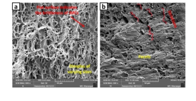
The Fig. 13 presents cross-sectional SEM micrographs of the fractured surfaces, revealing distinct differences in fracture morphology between UWFSW (Fig. 13a) and CFSW (Fig. 13b). The micrograph of the UWFSW joint clearly displays a higher density of dimples, which are characteristic of ductile fracture. These dimples are aligned parallel to the tensile axis, indicating that the material underwent significant plastic deformation before failure. In contrast, the CFSW joint exhibits numerous facets accompanied by striations, suggesting that the fracture occurred after limited plastic deformation. This fracture morphology is indicative of a brittle failure mechanism, where the material fails with minimal energy absorption. The increased presence of dimples in UWFSW compared to the more faceted structure in CFSW underscores the enhanced ductility of the UWFSW joint, resulting from the more controlled thermal environment and refined microstructure achieved through the underwater welding process.
Fig. 13.
SEM micrographs at the cross section of fracture surface of: (a) UWFSW and (b) CFSW.
Conclusions
This study examined the effects of underwater welding media on the joining process of Al to Ti, focusing on material flow and resulting mechanical properties. The following conclusions can be drawn from the experimental results:
Temperature measurements using thermocouples revealed that UWFSW effectively reduced welding temperatures and shortened thermal cycling time compared to CFSW. This reduction is achieved due to the cooling effect of the circulating water, which dissipates heat more efficiently. The predicted peak welding temperatures were 611℃ for CFSW and 584℃ for UWFSW.
Fe-SEM micrographs at the interface revealed that CFSW produced a thicker IMC layer (8.8 μm) compared to UWFSW (5.3 μm). This is due to higher temperatures and enhanced frictional heat in CFSW, which increased the diffusion rates of Al and Ti. Even though XRD confirmed the presence of the Al3Ti IMC phase in both processes, the IMC layer thickness critically influenced the mechanical properties of the weld.
EBSD analyses revealed distinct microstructural evolution at the Ti and Al interfaces and in the SZ. The Ti interface exhibited high recrystallization (83.97%) with localized heating from IMCs. The Al interface showed significant grain growth due to prolonged thermal exposure, with only 54% recrystallization. In the CSZUWFSW, fine equiaxed grains (1.4 μm) and 87% recrystallization were observed, with Ti particles acting as nuclei for particle-stimulated nucleation, reducing grain size and enhancing mechanical properties.
Texture analysis revealed that UWFSW produces more favourable recrystallization and shear textures, enhancing the mechanical properties and formability of Al-Ti welds. UWFSW exhibited weak basal textures at the Ti interface and strong recrystallization textures in the stir zone, while CFSW showed dominant basal textures and random stir zone textures due to complex material flow and inhomogeneous Ti particle distribution. These differences highlight the superior microstructural and mechanical properties achieved with UWFSW compared to CFSW.
UWFSW demonstrated greater microhardness in SZ due to its consistent fine-grain structure and finely dispersed Ti particles. In contrast, CFSW exhibited the lowest hardness, primarily because of the influence of intercalated IMC particles. Additionally, Al-Ti joints created using UWFSW achieved a maximum tensile strength of 267 MPa, approximately 13.4% higher than the 231 MPa achieved with CFSW, resulting in a joint efficiency of around 88%.
Author contributions
Conceptualization: Dr. Adepu Kumar and Dr. Saravana SundarMethodology: Dr. Adepu Kumar and Dr. Saravana SundarExperimental Work: Dr. Saravana SundarPost experimental analysis: Dr. Saravana SundarWriting and original draft preparation: Dr. Saravana Sundar and Dr. Radhika Review and editing of the initial draft: Dr. Adepu Kumar and Dr. RadhikaSupervision: Dr. Adepu Kumar and Dr. RadhikaAll authors have read and agreed to the submit the present version of the manuscript.
Data availability
The datasets used and/or analysed during the current study available from the corresponding author on reasonable request.
Declarations
Competing interests
The authors declare no competing interests.
Footnotes
Publisher’s note
Springer Nature remains neutral with regard to jurisdictional claims in published maps and institutional affiliations.
References
- 1.Wu, A. P., Song, Z. H., Nakata, K. & Liao, J. S. Defects and the properties of the dissimilar materials FSW joints of titanium alloy TC4 with aluminum alloy 6061. in Proceedings of the 1st International Joint Symposium on Joining and Welding 243–248 (2013). 10.1533/978-1-78242-164-1.243.
- 2.Dressler, U., Biallas, G. & Alfaro Mercado, U. Friction stir welding of titanium alloy TiAl6V4 to aluminium alloy AA2024-T3. Mater. Sci. Eng. A526, 113–117 (2009). [Google Scholar]
- 3.Sundar A, S., N, R. & Kumar, A. Optimizing tool offset in static shoulder friction stir welding of Al6061 to Ti6Al4V for enhanced joint integrity. J. Mater. Res. Technol.33, 1494–1503 (2024).
- 4.Ragunath, S., Radhika, N., Aravind Krishna, S. & Jeyaprakash, N. Synthesis of high entropy alloy for surface modification by friction stir process: Recent advances and future directions. Met. Mater. Int.30, 1170–1199 (2023). [Google Scholar]
- 5.Ambrosio, D., Morisada, Y., Ushioda, K. & Fujii, H. Extremely thin intermetallic layer in dissimilar AA6061-T6 and mild steel friction stir lap welding using a hemispherical tool. Sci. Rep.14, 1–8 (2024). [DOI] [PMC free article] [PubMed] [Google Scholar]
- 6.Shehabeldeen, T. A. et al. Investigation of the microstructure, mechanical properties and fracture mechanisms of dissimilar friction stir welded aluminium/titanium joints. J. Market. Res.11, 507–518 (2021). [Google Scholar]
- 7.A, S. S., Mugada, K. K. & Kumar, A. Enhancing microstructural, textural, and mechanical properties of Al-Ti dissimilar joints via static shoulder friction stir welding. J. Manuf. Sci. Eng. 1–32 (2023). 10.1115/1.4063358.
- 8.Hou, W., Ahmad Shah, L. H., Huang, G., Shen, Y. & Gerlich, A. The role of tool offset on the microstructure and mechanical properties of Al/Cu friction stir welded joints. J. Alloys Compd.825, 154045 (2020). [Google Scholar]
- 9.Song, Z., Nakata, K., Wu, A., Liao, J. & Zhou, L. Influence of probe offset distance on interfacial microstructure and mechanical properties of friction stir butt welded joint of Ti6Al4V and A6061 dissimilar alloys. Mater. Des.57, 269–278 (2014). [Google Scholar]
- 10.A, S. S., Kumar, A. & Kishore, K. Investigation of material flow , microstructure evolution , and texture development in dissimilar friction stir welding of Al6061 to Ti6Al4V. Mater Today Commun33, 104424 (2022).
- 11.Kim, Y. C. & Fuji, A. Factors dominating joint characteristics in Ti-Al friction welds. Sci. Technol. Weld. Join.7, 149–154 (2002). [Google Scholar]
- 12.Vijay, A. & Radhika, N. A comprehensive review on underwater welding: Methods, property evaluations and challenges. Adv. Mater. Process. Technol.10.1080/2374068X.2023.2184582 (2024). [Google Scholar]
- 13.Abdollahzadeh, A., Bagheri, B., Abassi, M., Kokabi, A. H. & Moghaddam, A. O. Comparison of the weldability of AA6061-T6 joint under different friction stir welding conditions. J. Mater. Eng. Perform.30, 1110–1127 (2021). [Google Scholar]
- 14.Papahn, H., Bahemmat, P., Haghpanahi, M. & Sommitsch, C. Study on governing parameters of thermal history during underwater friction stir welding. Int. J. Adv. Manuf. Technol.78, 1101–1111 (2015). [Google Scholar]
- 15.Derazkola, H. A. & Khodabakhshi, F. Underwater submerged dissimilar friction-stir welding of AA5083 aluminum alloy and A441 AISI steel. Int. J. Adv. Manuf. Technol.102, 4383–4395 (2019). [Google Scholar]
- 16.Chen, K., Liu, X. & Ni, J. A review of friction stir–based processes for joining dissimilar materials. Int. J. Adv. Manuf. Technol.104, 1709–1731 (2019). [Google Scholar]
- 17.Beygi, R. et al. Effect of alloying elements on intermetallic formation during friction stir welding of dissimilar metals: A critical review on aluminum/steel. Metals13, 768 (2023). [Google Scholar]
- 18.Shravan, C., Radhika, N., Deepak Kumar, N. H. & Sivasailam, B. A review on welding techniques: Properties, characterisations and engineering applications. Adv. Mater. Process. Technol.10.1080/2374068X.2023.2186638 (2024). [Google Scholar]
- 19.Mahto, R. P., Kinjawadekar, M., Gupta, C. & Pal, S. K. Effect of pin diameter in underwater friction stir lap welding of dissimilar materials: AA6061-T6 and AISI304. Lect. Not. Multidiscip. Ind. Eng. PartF164, 487–496 (2020). [Google Scholar]
- 20.Lader, S. K., Baruah, M. & Ballav, R. Significance of underwater friction stir welding on the weld integrity of thin sheets of aluminum (AA1050-O) and brass (CuZn34) joints. Mater. Sci. Eng. A865, 144627 (2023). [Google Scholar]
- 21.Lader, S. K., Baruah, M. & Ballav, R. Improvement in the weldability and mechanical properties of CuZn40 and AA1100-O dissimilar joints by underwater friction stir welding. J. Manuf. Process.85, 1154–1172 (2023). [Google Scholar]
- 22.Mao, Y., Qin, D., Xiao, X., Wang, X. & Fu, L. Achievement of high-strength Al/Cu dissimilar joint during submerged friction stir welding and its regulation mechanism of intermetallic compounds layer. Mater. Sci. Eng. A865, (2023).
- 23.Ji, S. M. et al. Characterization of Ti-6Al-4V alloy in the temperature range of warm metal forming and fracture analysis of the warm capping process. J. Mater. Res. Technol.18, 1590–1606 (2022). [Google Scholar]
- 24.Jiangwei, R., Yajiang, L. & Tao, F. Microstructure characteristics in the interface zone of Ti/Al diffusion bonding. Mater. Lett.56, 647–652 (2002). [Google Scholar]
- 25.Kattner, U. R., Lin, J. C. & Chang, Y. A. Thermodynamic assessment and calculation of the Ti-Al system. Metall. Trans. A Phys. Metall. Mater. Sci.s23, 2081–2090 (1992). [Google Scholar]
- 26.van Loo, F. J. J. & Rieck, G. D. Diffusion in the titanium-aluminium system—I. Interdiffusion between solid Al and Ti or Ti-Al alloys. Acta Metall. 21, 61–71 (1973).
- 27.Illeková, E. et al. Kinetics of intermetallic phase formation in the Ti/Al multilayers. Thermochim Acta469, 77–85 (2008). [Google Scholar]
- 28.Sujata, M., Bhargava, S. & Sangal, S. On the formation of TiAl3 during reaction between solid Ti and liquid Al. J. Mater. Sci. Lett.16, 1175–1178 (1997). [Google Scholar]
- 29.Zhao, H., Yu, M., Jiang, Z., Zhou, L. & Song, X. Interfacial microstructure and mechanical properties of Al/Ti dissimilar joints fabricated via friction stir welding. J. Alloys Compd.789, 139–149 (2019). [Google Scholar]
- 30.P., A. K., Yadav, D., Perugu, C. S. & Kailas, S. V. Influence of particulate reinforcement on microstructure evolution and tensile properties of in-situ polymer derived MMC by friction stir processing. Mater. Des.113, 99–108 (2017).
- 31.Lee, I. S., Hsu, C. J., Chen, C. F., Ho, N. J. & Kao, P. W. Particle-reinforced aluminum matrix composites produced from powder mixtures via friction stir processing. Compos. Sci. Technol.71, 693–698 (2011). [Google Scholar]
- 32.Satish Kumar, T., Shalini, S. & Thankachan, T. Friction stir processing based surface modification of AZ31 magnesium alloy. Mater. Manuf. Process.38, 1426–1435 (2023). [Google Scholar]
- 33.Kar, A., Yadav, D., Suwas, S. & Kailas, S. V. Role of plastic deformation mechanisms during the microstructural evolution and intermetallics formation in dissimilar friction stir weld. Mater. Charact.164, 110371 (2020). [Google Scholar]
- 34.Theyssier, M. C. & Driver, J. H. Recrystallization nucleation mechanism along boundaries in hot deformed Al bicrystals. Mater. Sci. En. A272, 73–82 (1999). [Google Scholar]
- 35.Magesh, M., Sathiskumar, R. & Kumar, T. S. Effect of tool pin profile on grain refinement, microstructure, and mechanical properties of AA2219-T62/Incoloy 800 joints developed via friction stir welding process. Trans. Indian Inst. Met.77, 737–746 (2024). [Google Scholar]
- 36.Liu, F. C., Liao, J., Gao, Y. & Nakata, K. Influence of texture on strain localization in stir zone of friction stir welded titanium. J. Alloys Compd.626, 304–308 (2015). [Google Scholar]
- 37.Yoon, S., Ueji, R. & Fujii, H. Microstructure and texture distribution of Ti-6Al-4V alloy joints friction stir welded below β-transus temperature. J. Mater. Process. Technol.229, 390–397 (2015). [Google Scholar]
- 38.Singh, R. K. R., Sharma, C., Dwivedi, D. K., Mehta, N. K. & Kumar, P. The microstructure and mechanical properties of friction stir welded Al–Zn–Mg alloy in as welded and heat treated conditions. Mater. Des.32, 682–687 (2011). [Google Scholar]
- 39.Hansen, N. Hall-Petch relation and boundary strengthening. Scr. Mater.51, 801–806 (2004). [Google Scholar]
- 40.Zhang, Z. & Chen, D. L. Contribution of Orowan strengthening effect in particulate-reinforced metal matrix nanocomposites. Mater. Sci. Eng. A483–484, 148–152 (2008). [Google Scholar]
- 41.Li, R. et al. Investigation of strengthening mechanism of commercially pure titanium joints fabricated by autogenously laser beam welding and laser-MIG hybrid welding processes. Int. J. Adv. Manuf. Technol.101, 377–389 (2019). [Google Scholar]
- 42.SaravanaSundar, A., Kumar, A. & Mugada, K. K. Minimizing material flow in the dissimilar joining of Al6061 and Ti6Al4V to mitigate the adverse effects of intermetallic compounds. Mater. Lett.350, 134956 (2023). [Google Scholar]
Associated Data
This section collects any data citations, data availability statements, or supplementary materials included in this article.
Data Availability Statement
The datasets used and/or analysed during the current study available from the corresponding author on reasonable request.


