Abstract
Magnetic resonance (MR) microscopy typically employs microcoils for enhanced local signal-to-noise ratio (SNR). Planar (surface) microcoils, in particular, offer the potential to be configured into array elements as well as to enable the imaging of extremely small samples because of the uniformity and precision provided by microfabrication techniques. Microcoils, in general, however, are copper-loss dominant, and cryo-cooling methods have been successfully used to improve the signal-to-noise ratio (SNR). Cryo-cooling of the matching network elements, in addition to the coil itself, has shown to provide the most improvement, but can be challenging with respect to cryostat requirements, cabling, and tuning. Here we present the development of a microfluidically cryo-cooled spiral microcoil with integrated microfabricated parallel plate capacitors, allowing for localized cryo-cooling of both the microcoil and the on-chip resonating capacitor to increase the SNR, while keeping the sample-to-coil distance within the most sensitive imaging range of the microcoil. Inductive coupling was used instead of a direct transmission line connection to eliminate the physical connection between the microcoil and the tuning network so that a single cryo-cooling microfluidic channel could enclose both the microcoil and the on-chip capacitor with minimum loss in cooling capacity. Comparisons between the cooled and uncooled cases were made via factor measurements and agreed well with the theoretically achievable improvement: the cooled integrated capacitor coil with inductive coupling achieved a factor of 2.6 improvement in factor over a reference coil conventionally matched and tuned with high- varactors and capacitively connected to the transmission line.
Keywords: cryogenic cooling, magnetic resonance (MR) microscopy, microfabricated planar microcoils, microfluidics, signal to noise ratio (SNR), inductive coupling
I. Introduction
Magnetic resonance (MR) microscopy has been enabled largely by the enhanced sensitivity obtained when using a microcoil, a small diameter coil that matches the sample size in scale, inducing a higher RF magnetic field strength per unit current [1, 2]. Various miniaturized transceiver or receiver coils such as solenoidal microcoils and planar microcoils have been developed in the past decade [2-14].
As coils get smaller, thermal noise from the conductors becomes the primary source of loss, reducing SNR as compared to what could be achieved if the sample were the dominant noise source. Conventional thought would suggest cryo-cooling of copper coils or the use of high temperature superconducting (HTS) coils to minimize the Johnson (thermal) noise of the coils and to improve SNR [15-23]. In fact, cryogenic cooling techniques have been used in a few small (centimeter-wide) coils using inductive coupling [23-26]. Due to the bulkiness of conventional cryostats, however, the coil to sample distance is typically not suitable for cryo-cooling microcoils since the most sensitive region of a coil is within approximately its diameter, requiring a very small sample to coil distance.
We recently presented a microfluidically cryo-cooled MR coil system using planar pair coils [27] and presented preliminary data for a microfluidically cryo-cooled spiral microcoil [28, 29]. The system successfully cryo-cooled the coil locally to liquid nitrogen temperature (−196°C) using a cryo-cooling microfluidic channel enclosing the coil, and demonstrated quality factor () enhancement of 1.8 times and SNR enhancement of 1.5 times without freezing samples placed less than 2 mm away from the coil.However, these values were lower than the theoretically predicted factor enhancement of 2.8 times and SNR enhancement of 3.3 times [16]. Further investigation revealed that the resistance of the tuning and matching network was higher than that of the microcoil itself, and thought to be the probable cause of the lower-than-expected and SNR enhancements. However, cryo-cooling the matching/tuning network was not possible using the microfluidic method due to both the bulkiness of conventional off-chip capacitors used for matching/tuning (several millimeter in widths and height) as well as the direct transmission line connection to the MR system that prevents a microfluidic channel from enclosing all these components for cryo-cooling.
To overcome these challenges, a microfluidically cryo-cooled planar microcoil with an integrated microfabricated parallel plate capacitor was developed and is presented here. The planar and integrated nature of the microfabricated capacitor allowed both the microcoil and the capacitor to be embedded inside a cryo-cooling microfluidic channel, while maintaining all the advantages of microfluidical cryo-cooling, namely the small coil-to-sample distance and minimized temperature effect on the imaging surface from the liquid nitrogen flowing through the cryo-cooling microfluidic channel. Physical transmission line connections to the microcoil were eliminated by using inductive coupling in order to allow cryo-cooling of the integrated resonating capacitor, in which signals detected by the primary microcoil in close proximity to the sample are coupled inductively to a secondary coil, which is then directly connected to the MR system through a transmission line. This method also increased cooling efficiency, since it prevented heat leakage through the transmission line. In addition to enabling the microcoil and the resonating capacitor to be cooled efficiently, a second minor but possibly important advantage of the inductive coupling arrangement is that it lets the microcoil be repositioned more easily than would be the case if the transmission line were connected to it directly. This may be advantageous due to the small field-of-view of the microcoil [30].
While inductive coupling does degrade the SNR somewhat due to additional losses caused by the secondary coil [31], it has been shown that such degradation can be kept to a minimum [32]. In fact, despite the small drop in SNR, inductive coupling has been used for several applications in MRI, such as enabling easily reconfigurable coil arrays [33], implantable probes for organ imaging [34], widening the bandwidth of the coil [35], and parallel MR imaging [36]. Recently, inductive coupling has also been used successfully in conjunction with microcoils. Sakellariou et al. used an inductively coupled solenoidal microcoil around a capillary tube to conduct a magic angle spinning experiment [37] and Utz et al. presented a solenoidal microcoil inside a commercial NMR probe to monitor flow inside a capillary [38]. Ryan et al. presented planar microcoils on a microfluidic chip inductively coupled to an NMR probe [9]. However inductive coupling of planar microfabricated coils for MRI applications have not been utilized in microfluidically cryo-cooled coil applications to maximize the cooling efficiency.
This paper describes an inductively coupled microfluidically cryo-cooled spiral microcoil with an integrated microfabricated parallel plate capacitor which is able to be fabricated in the formation of an array of coils for potential applications in MR microscopy or lab-on-a-chip systems.
II. Materials and methods
A. Theory
1). Effects of Cooling
When thermal noise from the conductors is the dominant noise source in coils, the SNR is proportional to the inverse of the square root of temperature and resistance as can be seen in (1) [39]:
| (1) |
where is the Boltzmann's constant, is the temperature, is the electrical resistance of the coil, is the frequency, is inductance of the coil and is the quality factor. In a series resonant circuit, . Reduced results in smaller thermal noise, leading to a higher .
does not change when the coil is cooled and the frequency is unchanged, therefore, the expected SNR improvement by cooling the coil can be given by:
| (2) |
When copper is cooled from room temperature to liquid nitrogen temperature (77K), its resistivity decreases by a factor of eight [40]. However, because the skin depth is proportional to the square root of resistivity, the high frequency resistance of copper at room temperature decreases by a factor of at liquid nitrogen temperature. Thus, the ideal SNR improvement obtained by cryo-cooling a copper coil to liquid nitrogen temperature is 3.3 fold [16].
2). Inductive Coupling
Figure 1 illustrates the concept of inductively coupled coils. The mutual inductance, an indicator of the degree of coupling efficiency, can be written as , where is the coupling constant and and are the inductance of the primary coil (microcoil) and the secondary coil, respectively. Measuring the variation in input resistance of the secondary coil is a standard and straightforward indicator of the mutual inductance or coupling efficiency, since the level of coupling changes with coil geometry and relative placement of the two coils. For a coupled system at room temperature, the ratio of the SNR of the coupled coil system to the SNR of the primary coil alone can be estimated by [32]:
| (3) |
Fig. 1.
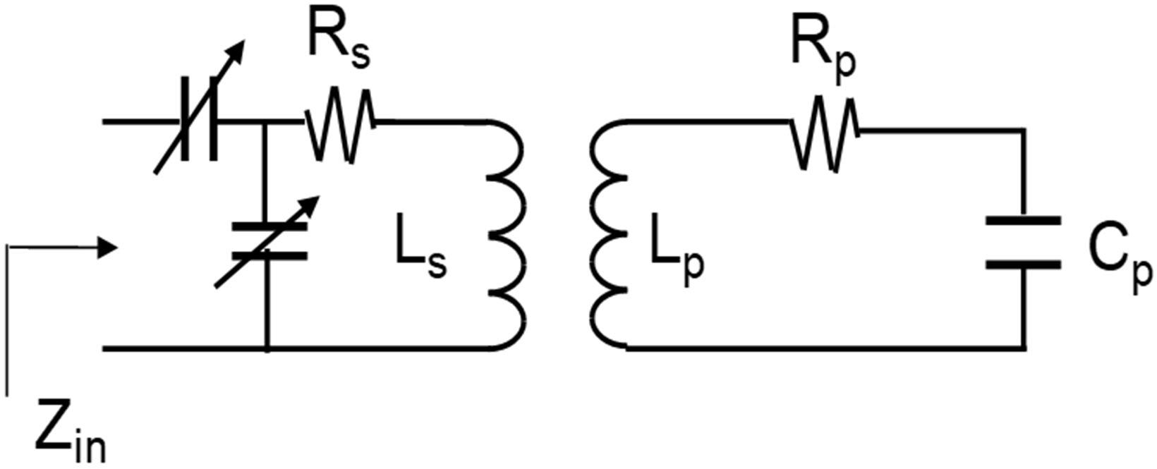
Conceptual circuit diagram for inductively coupled primary microcoil and secondary coil. and are the inductance of the microcoil and the secondary coil, respectively. and are the resistance of the microcoil and the secondary coil, respectively. is the capacitor to resonate the microcoil at 200 MHz.
and are the input resistance of the secondary coil coupled to the primary coil and the resistance of the secondary coil alone, respectively. To prevent a decrease in SNR of more than ten percent, we can show that should exceed that of the secondary coil alone by a factor of approximately five:
| (4) |
Since ideal direct coupling (transmission line connection) would create severe heat losses, sustaining a decrease in SNR of 10% or less due to inductive coupling was a reasonable sacrifice. In the case where the secondary coil is at room temperature, the resistive noise contributed by the secondary coil is at a higher noise temperature, and Eq. 3 can be modified to:
| (5) |
where is the temperature of the secondary coil and is the temperature of the primary coil. For a room temperature system, Eq. 5 reduces to Eq. 3, as expected. In this case, Eq.4 can be modified to:
| (6) |
Again, for a room temperature coil, Eq. 6 reduces to Eq. 4, as expected. In this case, to ensure the factor of less than ten percent degradation in SNR by using inductive coupling rather than physical connections, we can see that when the primary coil is cooled to 77 degrees and the secondary coil is at room temperature. The decrease in resistance of the cooled primary coil will account for nearly a factor of 17 increase in input resistance through the equations for the coupled circuit. Ultimately this places a lower bound on the size of the coil that can be used with a particular secondary coil without incurring an unacceptable loss in SNR due to inductive coupling.
B. Design
The cryo-cooled and inductively coupled microcoil device is composed of four layers as shown in Figure 2; a spiral surface microcoil for MR imaging (primary coil), a cryo-cooling microfluidic channel through which liquid nitrogen (LN) flows, a secondary coil for inductive coupling, and an imaging surface structure. The dimensions of the primary microcoil were chosen to be similar to that of Massin et al., who reported a planar spiral microcoil with high sensitivity [2]. A planar microcoil (2 mm inner diameter (ID), 3 turns, 40 μm trace width, 30 μm spacing, and 25 μm thick) was fabricated on a 0.5 mm polyetherimide (PEI) sheet. PEI has lower thermal conductivity (0.13 W/mK) than silicon (1.6 W/mK) or glass (1.1 W/mK), minimizing the heat flux between the cryo-cooled coil and the other surrounding area that is not cryo-cooled. PEI also has higher glass transition temperature (215°C) than poly(methyl methacrylate) (PMMA) (105°C) or polycarbonate (PC) (150°C). This makes it compatible with conventional photolithography where the use of temperatures as high as 150°C for the photoresist hard bake step were needed for the integrated parallel plate capacitor microfabrication. To resonate the microcoil at 200 MHz, the Larmor frequency of the 4.7 Tesla (T) MRI system used for imaging, a parallel plate capacitor (6.3 mm2 area) with a 15 μm thick SU-8 dielectric layer was microfabricated. A 3 mm wide and 1 mm high microfluidic channel was fabricated using poly(dimethylsiloxane) (PDMS) and bonded underneath the “microcoil-capacitor resonator” (microfabricated microcoil + microfabricated parallel plate capacitor), allowing for cryo-cooling of the entire microcoil resonator structure.
Fig. 2.
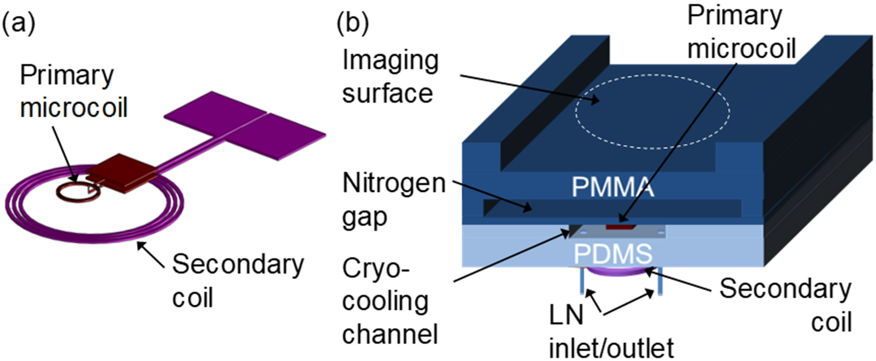
Schematic of the microfluidically cryo-cooled and inductively coupled MR microcoil device. (a) Primary spiral microcoil (2 mm inner diameter (ID), 3 turns, 40 μm trace width, 30 μm spacing, and 25 μm thickness) with an on-chip capacitor and the secondary coil (1 cm ID, 3 turns using 18 gauge magnet wire). (b) Cross sectional view of the integrated device. The nitrogen gas gap is 1.0 mm wide and the microcoil substrate is 0.5 mm thick. The total distance between the microcoil and the imaging sample is 1.8 mm. The distance between the primary microcoil and the secondary coil is 5 mm.
The secondary coil (1 cm ID, 3 turn solenoid) for inductive coupling was hand-wound from 18 gauge wire and positioned under the primary microcoil bonded with the cryo-cooling channel. To fix the position of the secondary coil, the coil was sealed with additional PDMS after alignment. The matching network of the secondary coil was designed and constructed with conventional capacitors and connected with standard RG-58 50 Ω coaxial cable to the MR system.
The imaging surface on which samples are placed was separated from the microcoil substrate using a 1 mm high nitrogen gas gap supported by two vertical side-support structures. This provided thermal isolation during cryo-cooling of the microcoil system to prevent samples from freezing during MR image acquisition, while minimizing the coil-to-sample distance. The final distance between the coil and sample was 1.8 mm, less than the several millimeters of coil-to-sample distance previously reported by other researchers [20, 41, 42]. It is worth noting that Bruker’s Cryoprobe™ provides 1 mm separation between the coil and sample, but does require an additional heating device to keep the sample from freezing [43].
C. Fabrication Details
Figure 3 illustrates the overall fabrication steps of the MR surface microcoil and the integrated parallel plate capacitor. A chromium/copper (30/300 nm) seed layer was deposited on a 0.5 mm thick and 76 mm x 76 mm PEI substrate (Ultem® 1000, SabicGE Plastics, Boedeker Plastics, Shiner, TX) using an electron-beam evaporator (Fig. 3a). Then, a 35 μm thick photoresist (NR21-20000P, Futurrex Inc., Franklin, NJ) was spun, and the microcoil and the bottom side plate of the parallel plate capacitor were defined using a photolithography process (Fig. 3b). Following photolithography, 25 μm of copper was electroplated using a copper sulfate solution (CuSO4 : H2SO4 : H2O = 250 g : 25 ml : 1 L) at a current density of 10 mA/cm2. The photoresist was removed by photoresist remover (RR4, Futurrex Inc.) instead of commonly used acetone to prevent the PEI substrate from being damaged by the solvent. The chromium/copper seed layer was etched by chrome etchant (TFE, Transene Company Inc., Danvers, MA) and copper etchant (CE-100, Transene Company Inc) (Fig. 3c). Afterwards, the coil substrate was coated with a 15 μm thick SU-8 2015 layer (MicroChem, Newton, MA) as the dielectric layer between the parallel plate capacitor. A post for electrical connection between the microcoil and the capacitor was defined using a second photolithography step, followed by electroplating copper to a thickness of 15 μm (Fig. 3d). The relative permittivity of SU-8 is 4.1 at 1 GHz at room temperature [44]. The substrate was then placed on a 150°C hot plate for 30 min to hard-bake the SU-8 layer. Then, another chromium/copper (30/300 nm) seed layer was deposited on the substrate and a 35 μm thick NR21-20000P photoresist layer was coated on it to photolithographically define the top side plate of the parallel plate capacitor (Fig. 3e). After electroplating of a 25 μm thick copper layer using the photolithographically defined electroplating mold of the top capacitor plate, the metal seed layer and the photoresist were removed (Fig. 3f). Finally, a 30 μm thick PDMS layer was coated on the substrate to bond the microcoil resonator system to the cryo-cooling microfluidic channel. This also prevented the microcoil resonator system from being detached from the substrate due to thermal stress during cryo-cooling.
Fig. 3.
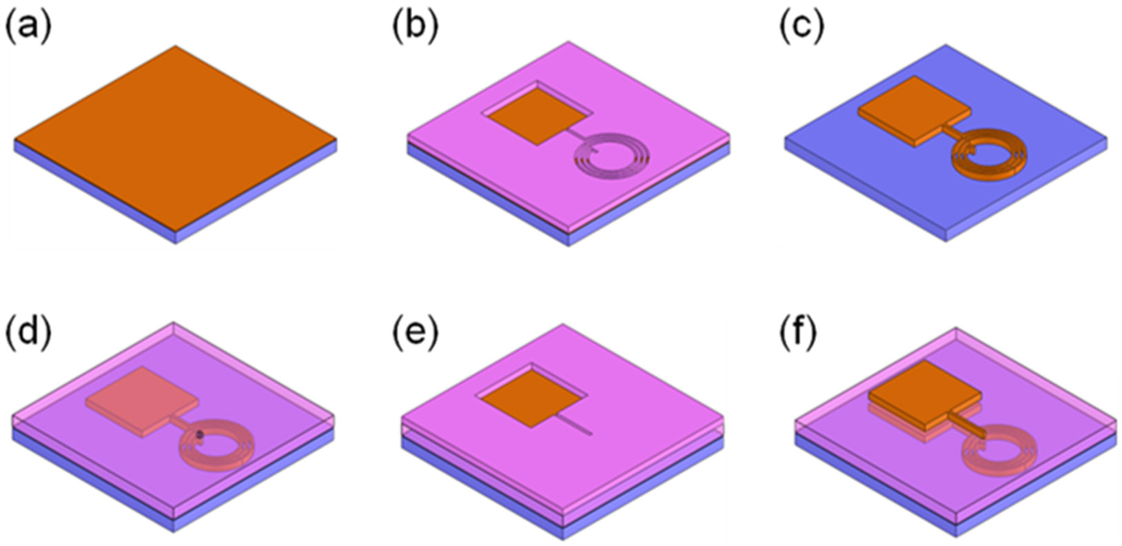
Fabrication processes for the spiral microcoil and the integrated parallel plate capacitor. (a) Cr/Cu seed layer deposition on a thin substrate. (b) negative photoresist patterned to define the lower capacitor plate and the microcoils. (c) Cu electroplating to 25 μm height, removal of the photoresist and the Cr/Cu seed layer. (d) SU-8TM patterned for the dielectric layer of the capacitor and the connection post between the coil and the capacitor, followed by Cu electroplating. (e) Cr/Cu seed layer deposition on the SU-8TM layer and negative photoresist patterning to define the upper capacitor plate and the connection traces between the coil and the capacitor. (f) Cu electroplating to 25 μm height, removal of the photoresist and the Cr/Cu seed layer.
The cryo-cooling microfluidic channel for liquid nitrogen delivery to the microcoil was fabricated in PDMS using soft lithography (Fig. 4). The acrylic master mold was cut using a rapid prototyping machine (MDX-40, Roland DGA Corp., Irvine, CA). After 3.18 mm outer diameter (OD) silicone tubings were placed on the inlet and outlet area of the master mold, uncured PDMS was applied to the mold. The released polymerized PDMS replica from the master mold was then bonded to the previously fabricated microcoil substrate coated with a thin PDMS layer.
Fig. 4.

Fabrication steps for the cryo-cooling microfluidic channel structure. (a) Acrylic master mold fabrication using a rapid prototyping machine. (b) Silicone tubing insertion and PDMS pouring. (c) PDMS curing and releasing.
The secondary coil was positioned 5 mm below the primary microcoils (Fig. 5a, b). To fix the position of the secondary coils, the coils were sealed with additional PDMS after the alignment. The nitrogen gap and the imaging surface were created in an acrylic block (80 × 210 × 12 mm) using the rapid prototyping machine. A small pillar array (1 mm in width, 2 mm in length, and same height as the nitrogen gap) was fabricated inside the nitrogen gap to prevent the gap from collapsing under an external clamping force required for the final assembly.
Fig. 5.

(a) Microfabricated spiral microcoils with an integrated parallel plate capacitor for resonating at 200 MHz at RT and LT. (b) Integrated device with the microcoil resonator, a LN cryo-cooling channel, and a secondary coil. The image shows two systems on a single substrate. (c) The device having an imaging phantom (0.1% CuSO4) on top of the imaging surface ready for MR imaging.
For the final assembly step, the planar coil substrate bonded with the cryo-cooling microfluidic channel was attached to the acrylic frame using Kapton tape to form the closed nitrogen gap channel (Fig. 5c). Nylon screws were used to clamp this sandwich structure to an acrylic cradle, which was loaded to the center of the magnet. The liquid nitrogen tubing and nitrogen gas tubing (6.35 mm OD polyethylene tubing) were attached to the acrylic board, and the liquid nitrogen dewar (Lab20 with withdrawal, Chart Industries, Inc., Garfield Heights, OH) and the nitrogen gas cylinder were connected to the liquid nitrogen tubing and nitrogen gas tubing, respectively. To drive liquid nitrogen out from the dewar, nitrogen gas was pumped into the dewar. To prevent heat loss due to conduction and convection in the polyethylene tubing used for liquid nitrogen delivery to the PDMS microfluidic channel, the tubing was wrapped with insulating sponge foam tape (Frost King, Mahwah, NJ).
D. Characterization
1). Characterization of Inductive Coupling Efficiency
Before characterizing the factor of the fabricated microcoil resonator system, the coupling efficiency between the primary microcoil resonator and the secondary coil was first characterized. Input resistance of the secondary coil (open-circuited) was measured using a network analyzer (HP 4195A) and used as the indicator of the ratio of the SNR of the coupled coil system to the SNR of the primary coil alone as explained in the theoretical discussion of inductive coupling above (Section II.A.2).
2). Characterization of the Microfabricated Capacitor
The characteristics of the microfabricated capacitor at room temperature (RT) and liquid nitrogen temperature (LT) were important parameters to be considered when characterizing the and SNR improvement due to cryo-cooling. Therefore, to examine changes in the relative permittivity of the SU-8 layer at RT and LT (which would affect resonant frequencies) and the dielectric loss at RT and LT (which would affect relative improvement), an isolated parallel plate capacitor (3 mm x 4 mm) with a 15 μm thick SU-8 dielectric layer was fabricated without an accompanying microcoil. The network analyzer was calibrated with a coaxial probe using port extension and compensation. This probe was then soldered to the microfabricated capacitor. The capacitance and series resistance of the capacitor were measured at RT and then LT after immersing the capacitor in a liquid nitrogen bath in order to characterize the effects of the microfabricated capacitor alone.
3). Characterization of Improvement
To characterize the expected improvement in SNR that could be achieved by the microcoil-capacitor resonator compared to a “conventional microcoil”, the of the microcoil-capacitor resonator at RT and LT was measured on the bench and compared to the of a conventionally tuned and fed microcoil. Specifically, the same spiral microcoil was used at RT and LT, but tuned with high- varactors (MV34009, Microsemi, Lowell, MA) rather than the microfabricated capacitor and connected with a transmission line rather than inductively coupled. The microcoil-capacitor resonator was tuned to the operating frequency of 200 MHz by trimming small areas of the capacitor under a microscope until the desired resonant frequency was reached.
The of the microcoil-capacitor resonator was measured as , where is the center frequency of the resonator and is the half power bandwidth, from the S21 measurement after two decoupled probes were brought close to the microcoil-capacitor resonator. For the measurement of the conventional microcoil, the transmission line of the conventional microcoil was connected to the HP 4195A network analyzer, and and (bandwidth of the −7dB points on the S11 measurement) were measured. The measurement with this technique has been shown previously to agree with the dual probe method for unloaded measurement [45, 46].
To cryo-cool the “conventional microcoil”, the coil plus matching/tuning network was physically dipped in liquid nitrogen. Since such setup is not feasible for imaging, these comparison measurements were restricted to the bench measurement of factors. The factor improvement of the microcoil-capacitor resonator was characterized by comparing the factor of the microcoil-capacitor resonator at LT to the factor of the conventional microcoil at RT. This factor improvement was then compared to the factor improvement of the conventional microcoil at LT against RT. The expected improvement in SNR using the microcoil-capacitor resonator against the conventional microcoil was estimated by:
| (7) |
as described theoretically by (2).
4). Characterization with MR Imaging
Imaging was performed in a 4.7 T MRI system (40 cm bore, Unity/Inova console, Varian, Palo Alto, CA). RT MR images of a phantom (0.1% copper sulfate solution) were acquired in the axial plane (perpendicular to the imaging surface and the plane of the coil), with the coil operating in transmit/receive mode in order to avoid the additional complexity of decoupling from a separate transmit coil. All images were acquired using a standard spin echo sequence with a matrix size of 128 × 128, field-of-view of 50 × 30 mm, TR (repetition time) of 500 ms, TE (echo time) of 31 ms, two averages, slice thickness of 0.5 mm, and spectral width of 20 kHz. Once 10 and 16 dB for 90°/180° tipping was selected, RT images were acquired in the axial plane. LT images were then obtained after flowing liquid nitrogen to the microcoil.
MATLAB was used to reconstruct images and evaluate image SNR. An SNR matrix was obtained by dividing the signal magnitude matrix by the average value of a large noise region outside the phantom.
5). Analysis the Effects of Coil-to-Sample Distance
In this design, the nitrogen gap of 1 mm, the microcoil substrate of 0.5 mm, and the imaging surface of 0.3 mm together lead to a coil-to-sample spacing of 1.8 mm. As the focus of this particular work was to increase the improvement in achieved with microfluidic cryo-cooling to match the theoretically predicted improvement, minimizing the coil-to-sample distance was not of immediate concern. However, for completeness, the system was modeled to predict the coil-to-sample spacing at which cryo-cooling no longer provides a benefit over a conventional, uncooled coil placed directly on the sample. The microcoil dimensions used in the simulation were the same as the cooled coil described above (inner diameter: 2 mm, trace width: 40 μm, trace gap: 30 μm, and the height of trace: 25 μm). The feed loop trace was 100 μm below the main trace and the capacitor used to resonate the microcoil at 200 MHz was assumed to be lossless. A coil-to-sample spacing of 0.2 mm was used, which was the minimum distance in practice due to the thickness of the imaging surface substrate.
III. Results & Discussion
A. Inductive Coupling Efficiency
The measurement of an input resistance less than 1 ohm using a conventional network analyzer is extremely difficult because the accuracy of a network analyzer is over 1 ohm error in input resistance for a 50 ohm system [47]. Hence, the of the secondary coil at 200 MHz was measured instead of the resistance, and the resistance of the secondary coil was then calculated using the R-L-C circuit equation of , where is the angular frequency and is the inductance. Using this method, the input resistance of the isolated secondary coil at 200 MHz was calculated to be 0.69 ohm.
When the secondary coil was centered 5 mm above the cryo-cooled microcoil-capacitor resonator, an input resistance of 7.22 ohms was measured. Since this resistance was about 9.6 times larger than the input resistance measured without inductive coupling, this inductive coupling resulted in approximately 17% degradation in SNR. As described in the theoretical discussion of inductive coupling above (Section II.A.2), the input resistance should increase 17 times to maintain less than 10 percent degradation in SNR. Therefore, in future work, to obtain higher coupling efficiency, the number of turns on the microcoil needs to be increased or the coil (microcoil and secondary coil) dimensions and geometry should be optimized. However, for the purpose of demonstrating the effectiveness of microfluidically cryo-cooling the resonating capacitor as well as the microcoil, it was not necessary to optimize the inductive coupling.
B. Characterization of the Microfabricated Capacitor
The relative permittivity of the microfabricated capacitor was characterized by measuring its capacitance. At RT, the microfabricated capacitor had a capacitance of 31 pF. At LT, the capacitance decreased to 24 pF. Based on the measurement, the relative permittivity of SU-8 at 200 MHz can be estimated to be 4.3 at RT and 3.4 at LT. The 22% decrease in capacitance measured after cryo-cooling resulted in a shift of the resonant frequency of the microcoil resonator and corresponded well to an observed 12% increase in resonant frequency during cryo-cooling according to the LC resonance equation (). The practical effect of the change of the relative permittivity of SU-8 is that two separate microcoils were required to be fabricated in order to tune the coils at RT and LT, respectively.
Unfortunately, along with the dielectric constant, the dielectric loss in the SU-8 also changed with temperature (higher at room temperature), making the improvement ( at LT () vs. at RT ()) for the microcoil-capacitor resonator artificially high ( improvement of 5.8 times). The dielectric loss of the microfabricated capacitor was characterized by measuring its series resistance. At RT, the microfabricated capacitor had a series resistance of 1.5 ohms and at LT, the series resistance became too small to measure. The high series resistance of the SU-8 layer at room temperature (=1.5 ohms) resulted in a low of the microcoil resonator, artificially increasing the ratio of to . Therefore, the comparison was made to the of a conventional microcoil at RT (described in the next (Section III.C)), instead of the microcoil-capacitor resonator at RT.
C. Characterization of factor of the Fabricated MR Microcoil System
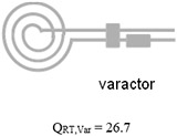
Table 1 summarizes the measurements acquired at RT and LT from two microcoils, one using high- varactors with a transmission line (conventional microcoil) and another one using the microfabricated on-chip capacitor without a transmission line (microcoil-capacitor resonator). With the microcoil using high- varactors, the increased by 1.8 fold when microfluidically cryo-cooling only the microcoil. The further increased by 2.4 fold when both the microcoil and the matching/tuning network were cryo-cooled through direct dipping in liquid nitrogen. The improvement when comparing the conventional microcoil at RT, , to the microcoil-capacitor resonator at LT, , was 2.6 fold. This improvement matches well to the theoretically predicted enhancement of 2.8 fold when cryocooling both the coils and the matching/tuning network [27], and is significantly higher (= 144%) than the enhancement of 1.8-fold previously achieved by our team when cryo-cooling only the microcoil and not the matching/tuning network. In addition, as validation, this improvement of 2.6 times obtained from the microcoil-capacitor resonator was in line with the improvement of 2.4 (= 63.7/26.7) obtained when comparing the of the conventional microcoil at RT () to LT () obtained when directly dipping the conventional microcoil and varactors into a liquid nitrogen bath. Therefore, the developed microfluidically cryo-cooled microcoil resonator system performance is in line with a microcoil system with off-chip varactors, at the same time providing much better integrability, system compactness, practicality, and ease of system production.
TABLE I.
factor of a directly coupled 3-turn microfabricated spiral microcoil at room temperature and liquid nitrogen temperature
|
(Cryo-cooling only microcoil) |
(Cryo-cooling both microcoil and matching/tuning network) |
||
|---|---|---|---|
| Microfabricated coil resonated with high- varactors |
|
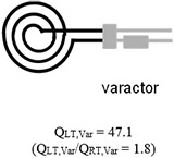
|
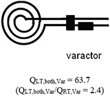
|
| Microfabricated coil resonated with on-chip capacitor |
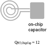 (Note: Q of microfabricated capacitor is very low due to lossy SU-8) |
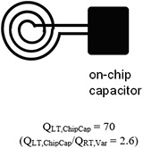
|
Gray indicates room temperature components and black indicates cryo-cooled components. data of the microfabricated coil resonated with on-chip capacitor were reported in the microTAS conference [29].
D. MR Imaging with the Inductively Coupled Microcoils
Figure 6a shows the position of the primary microcoil and the secondary coil, the nitrogen gap, and the phantom to be imaged. Figure 6b shows the image obtained by the secondary coil without the microcoil-capacitor resonator coupled. It shows a much larger area excited by the secondary coil than when the microcoil-capacitor resonator coupled (Fig. 6c). This shows that the sensitivity pattern of the inductively coupled system is dominated by the primary coil, as suggested by the resistance measurements with the microcoil coupled to the secondary coil. Figure 6c and d show the transverse images obtained at RT and LT with the microcoil coupled to the secondary coil. SNR comparison of both images was not considered valid due to the artificial improvement between RT and LT discussed in Section III.B.
Fig. 6.
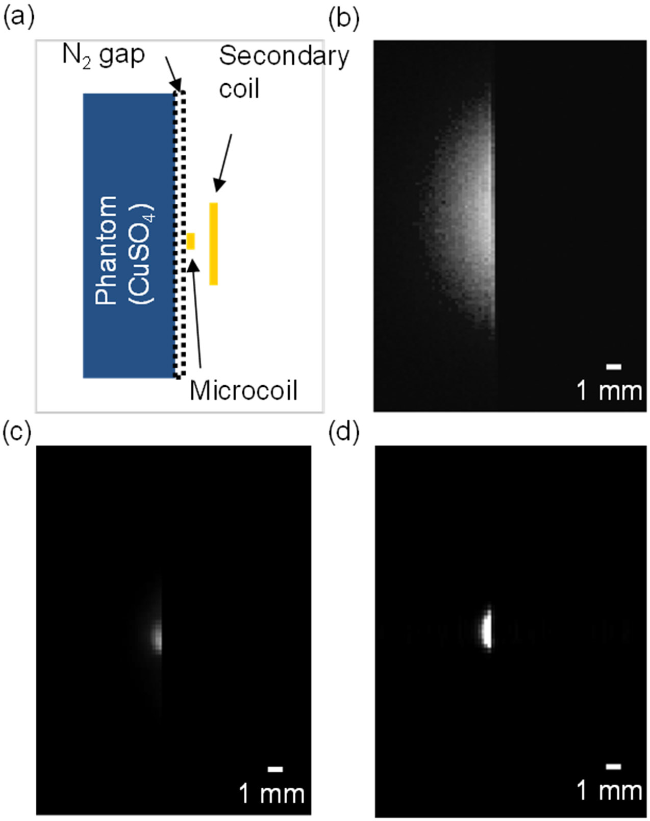
Transverse spin echo images, acquired with the secondary coil, RT microcoil and LT microcoil (using 50 × 30 mm field of view and approximately 90° 180° flip angles). (a) Illustration of the position of the phantom, the microcoil, and the secondary coil. (b) Secondary coil image (no microcoil coupled). (c) RT microcoil image. (d) LT microcoil image.
E. Analyzing the Effect of Coil-to-Sample Distance on SNR Improvement
Figure 7 shows the simulated relationship between the normalized relative SNRs of a cryo-cooled microcoil and an uncooled microcoil against coil-to-sample distance. The normalized relative SNR of the uncooled microcoil with 0.2 mm of coil-to-sample distance is about 0.95. To match this or provide improvement, the cryo-cooled microcoil needs to have a coil-to-sample distance of 1.25 mm or less. If 10% degradation in SNR, which is a reasonable sacrifice due to inductive coupling, is taken into account, the distance has to be 1.15 mm or less.
Fig. 7.
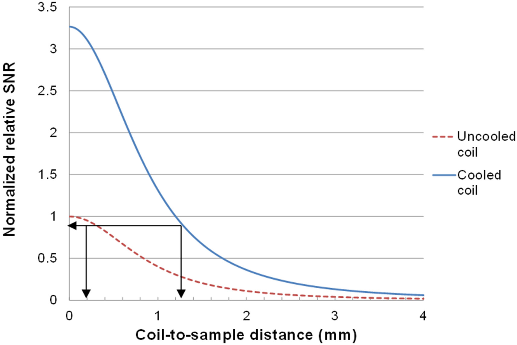
Simulation result of the normalized relative SNR of uncooled and cooled microcoil against the coil-to-sample distance. When the sample is placed 0.2 mm above the uncooled microcoil, the normalized relative SNR is about 0.95. To have equivalent SNR, the cooled microcoil needs to have a coil-to-sample distance of 1.25 mm or less.
Coil-to-sample distance in the current design can be reduced to 1.3 mm with relative ease by reducing the imaging surface substrate thickness from 0.3 mm to 0.2 mm and by reducing the thickness of the substrate on which the microcoil is fabricated from 0.5 mm to 0.15 mm. Further reduction in coil-to-sample distance needs to be achieved through reducing the depth of the nitrogen gas gap. A nitrogen gas gap reduced to 0.8 mm (currently at 1 mm) is expected to give the same relative SNR as the uncooled microcoil with the sample placed right on top of the microcoil. Thus, any further reduction in this gap will result in net SNR improvement over conventional microcoil at room temperature. One strategy for achieving a shallower nitrogen gas gap without influencing the imaging surface temperature is to utilize warm nitrogen gas instead of room temperature nitrogen gas that is currently being used, thus improving the insulation capability of the nitrogen gas gap.
For the comparison of the probe sensitivity, especially for spectroscopy applications, some investigators report the limit of detection (LOD). Massin et al. presented an LOD of 115 nMol at 300 MHz [2]. The primary coil reported here is essentially the same in structure to the coil of Massin et al. except for using three turns rather than two turns. Taking into account the SNR ratio between the uncooled coil with the coil-to-sample distance of 65 μm (Massin et al.) and the cooled microcoil with the coil-to-sample distance of 1.8 mm (our result), the estimated LOD of our coil at 300 MHz is 272 nMol. If we further reduce the coil-to-sample distance to 1.3 mm as described above, our expected LOD will be 143 nMol.
IV. Conclusion
A microfluidically cryo-cooled spiral microcoil system with an integrated microfabricated capacitor and utilizing inductive coupling for MR microscopy has been developed and a significant improvement in factor was demonstrated. The use of a microfabricated parallel plate capacitor integrated with the microcoil and inductive coupling to eliminate transmission line connections allowed both the microcoil and the resonating capacitor to be enclosed by the microfluidically cryo-cooling system. This enabled localized cryo-cooling of the entire microfabricated microcoil-capacitor resonator structure without freezing the sample, while maintaining a coil-to-sample distance within a coil width of the microcoil. The system provided a 2.6 fold improvement in factor compared to a conventional microcoil with high- varactors and transmission line connection, and provided the expected improvement over our previous system that reported an improvement of 1.8 with only the coil part cryo-cooled. The result validates that cryo-cooling both the microcoil and the matching/tuning network provides a larger improvement than cryo-cooling only the microcoil itself, with the achieved 2.6 fold improvement being close to the theoretically predicted maximum improvement of 2.8 fold. This system may allow multiple primary microcoils to be used with a single or multiple secondary coils for effectively enabling larger or multiple fields-of-view MR microscopy.
Acknowledgment
This work was supported by the National Institutes of Health / National Institute of Biomedical Imaging and Bioengineering (NIH/NIBIB) under grant 1R21EB07297.
Contributor Information
Chiwan Koo, Department of Biomedical Engineering, Texas A&M University, College Station, TX 77843 USA.
Richard F. Godley, Department of Electrical and Computer Engineering, Texas A&M University, College Station, TX 77843 USA.
Mary P. McDougall, Department of Biomedical Engineering, Texas A&M University, College Station, TX 77843 USA..
Steven M. Wright, Department of Electrical and Computer Engineering, Texas A&M University, College Station, TX 77843 USA..
Arum Han, Department of Electrical and Computer Engineering, Texas A&M University, College Station, TX 77843 USA.
References
- [1].Olson DL, Peck TL, Webb AG, Magin RL, and Sweedler JV, "High-Resolution Microcoil 1H-NMR for Mass-Limited, Nanoliter-Volume Samples," Science, vol. 270, pp. 1967–1970, 1995. [Google Scholar]
- [2].Massin C, Vincent F, Homsy A, Ehrmann K, Boero G, Besse PA, Daridon A, Verpoorte E, de Rooij NF, and Popovic RS, "Planar microcoil-based microfluidic NMR probes," Journal of Magnetic Resonance, vol. 164, pp. 242–255, 2003. [DOI] [PubMed] [Google Scholar]
- [3].Walton JH, de Ropp JS, Shutov MV, Goloshevsky AG, McCarthy MJ, Smith RL, and Collins SD, "A Micromachined Double-Tuned NMR Microprobe," Analytical Chemistry, vol. 75, pp. 5030–5036, 2003. [Google Scholar]
- [4].Eroglu S, Gimi B, Roman B, Friedman G, and Magin RL, "NMR spiral surface microcoils: Design, fabrication, and imaging," Concepts in Magnetic Resonance Part B: Magnetic Resonance Engineering, vol. 17B, pp. 1–10, 2003. [Google Scholar]
- [5].Wensink H, Benito-Lopez F, Hermes DC, Verboom W, Gardeniers HJGE, Reinhoudt DN, and van den Berg A, "Measuring reaction kinetics in a lab-on-a-chip by microcoil NMR," Lab on a Chip, vol. 5, pp. 280–284, 2005. [DOI] [PubMed] [Google Scholar]
- [6].Ehrmann K, Saillen N, Vincent F, Stettler M, Jordan M, Wurm FM, Besse P-A, and Popovic R, "Microfabricated solenoids and Helmholtz coils for NMR spectroscopy of mammalian cells," Lab on a Chip, vol. 7, pp. 373–380, 2007. [DOI] [PubMed] [Google Scholar]
- [7].Badilita V, Kratt K, Baxan N, Mohmmadzadeh M, Burger T, Weber H, Elverfeldt D. v., Hennig J, Korvink JG, and Wallrabe U, "On-chip three dimensional microcoils for MRI at the microscale," Lab on a Chip, vol. 10, pp. 1387–1390, 2010. [DOI] [PubMed] [Google Scholar]
- [8].Weber H, Baxan N, Paul D, Maclaren J, Schmidig D, Mohammadzadeh M, Hennig J, and von Elverfeldt D, "Microcoil-based MRI: feasibility study and cell culture applications using a conventional animal system," Magnetic Resonance Materials in Physics, Biology and Medicine, vol. 24, pp. 137–145, 2011. [DOI] [PubMed] [Google Scholar]
- [9].Ryan H, Song S-H, Zaß A, Korvink J, and Utz M, "Contactless NMR Spectroscopy on a Chip," Analytical Chemistry, vol. 84, pp. 3696–3702, 2012. [DOI] [PubMed] [Google Scholar]
- [10].Gruschke OG, Baxan N, Clad L, Kratt K, von Elverfeldt D, Peter A, Hennig J, Badilita V, Wallrabe U, and Korvink JG, "Lab on a chip phased-array MR multi-platform analysis system," Lab on a Chip, vol. 12, pp. 495–502, 2012. [DOI] [PubMed] [Google Scholar]
- [11].Massin C, Boero G, Vincent F, Abenhaim J, Besse PA, and Popovic RS, "High- factor RF planar microcoils for micro-scale NMR spectroscopy," Sensors and Actuators A: Physical, vol. 97-98, pp. 280–288, 2002. [Google Scholar]
- [12].Ehrmann K, Pataky K, Stettler M, Wurm FM, Brugger J, Besse P-A, and Popovic R, "NMR spectroscopy and perfusion of mammalian cells using surface microprobes," Lab on a Chip, vol. 7, pp. 381–383, 2007. [DOI] [PubMed] [Google Scholar]
- [13].Boero G, Frounchi J, Furrer B, Besse P-A, and Popovic RS, "Fully integrated probe for proton nuclear magnetic resonance magnetometry," Review of Scientific Instruments, vol. 72, pp. 2764–2768, 2001. [Google Scholar]
- [14].Eroglu S, Friedman G, and Magin RL, "Estimate of losses and signal-to-noise ratio in planar inductive micro-coil detectors used for NMR," Magnetics, IEEE Transactions on, vol. 37, pp. 2787–2789, 2001. [Google Scholar]
- [15].Hurlston SE, Brey WW, Suddarth SA, and Johnson GA, "A high-temperature superconducting Helmholtz probe for microscopy at 9.4 T," Magnetic Resonance in Medicine, vol. 41, pp. 1032–1038, 1999. [DOI] [PubMed] [Google Scholar]
- [16].Wright AC, Song HK, and Wehrli FW, "In Vivo MR Micro Imaging With Conventional Radiofrequency Coils Cooled to 77°K," Magnetic Resonance in Medicine, vol. 43, pp. 163–169, 2000. [DOI] [PubMed] [Google Scholar]
- [17].Ginefri J-C, Darrasse L, and Crozat P, "High-Temperature Superconducting Surface Coil for In Vivo Microimaging of the Human skin," Magnetic Resonance in Medicine, vol. 45, pp. 376–382, 2001. [DOI] [PubMed] [Google Scholar]
- [18].Wosik J, Wang F, Xie LM, Strikovski M, Kamel M, Nesteruk K, Bilgen M, and Narayana PA, "High-Tc superconducting surface coil for 2 tesla magnetic resonance imaging of small animals," Applied Superconductivity, IEEE Transactions on, vol. 11, pp. 681–684, 2001. [Google Scholar]
- [19].Wosik J, Lei-Ming X, Nesteruk K, Lian X, Bankson JA, and Hazle JD, "Superconducting single and phased-array probes for clinical and research MRI," Applied Superconductivity, IEEE Transactions on, vol. 13, pp. 1050–1055, 2003. [Google Scholar]
- [20].Ratering D, Baltes C, Nordmeyer-Massner J, Marek D, and Rudin M, "Performance of a 200-MHz cryogenic RF probe designed for MRI and MRS of the murine brain," Magnetic Resonance in Medicine, vol. 59, pp. 1440–1447, 2008. [DOI] [PubMed] [Google Scholar]
- [21].Brey WW, Edison AS, Nast RE, Rocca JR, Saha S, and Withers RS, "Design, construction, and validation of a 1-mm triple-resonance high-temperature-superconducting probe for NMR," Journal of Magnetic Resonance, vol. 179, pp. 290–293, 2006. [DOI] [PubMed] [Google Scholar]
- [22].Styles P, Soffe NF, Scott CA, Crag DA, Row F, White DJ, and White PCJ, "A high-resolution NMR probe in which the coil and preamplifier are cooled with liquid helium," Journal of Magnetic Resonance, vol. 60, pp. 397–404, 1984. [DOI] [PubMed] [Google Scholar]
- [23].Black R, Early T, Roemer P, Mueller O, Mogro-Campero A, Turner L, and Johnson G, "A high-temperature Superconducting Receiver for Nuclear Magnetic Resonance Microscopy," Science, vol. 259, pp. 793–795, 1993. [DOI] [PubMed] [Google Scholar]
- [24].Black RD, Roemer PB, and Mueller OM, "Electronics for a High Temperature Superconducting Receiver system for Magnetic Resonance Microimaging," IEEE Transactions on Biomedical Engineering, vol. 41, pp. 195–197, 1994. [DOI] [PubMed] [Google Scholar]
- [25].Ma QY, Chan KC, Kacher DF, Gao E, Chow MS, Wong KK, Xu H, Yang ES, Young GS, Miller JR, and Jolesz FA, "Superconducting RF Coils for Clinical MR Imaging at Low Field," Academic Radiology, vol. 10, pp. 978–987, 2003. [DOI] [PubMed] [Google Scholar]
- [26].Wosik J, Xue L, Xie L-M, Kamel MR, Nesteruk K, and Bankson JA, "Superconducting array for high-field magnetic resonance imaging," Applied Physics Letters, vol. 91, p. 183503, 2007. [Google Scholar]
- [27].Koo C, Godley RF, Park J, McDougall MP, Wright SM, and Han A, "A magnetic resonance (MR) microscopy system using a microfluidically cryo-cooled planar coil," Lab on a Chip, vol. 11, pp. 2197–2203, 2011. [DOI] [PMC free article] [PubMed] [Google Scholar]
- [28].Koo C, Carillo MA, McDougall MP, Wright SM, and Han A, "A Cryo-Cooling Microfluidic Device for Magnetic Resonance (MR) Microscopy System," in μTAS 2010, The 14th International Conference on Miniaturized Systems for Chemistry and Life Sciences, Groningen, The Netherlands, 2010, pp. 614–616. [Google Scholar]
- [29].Koo C, Godley R, McDougall MP, Wright SM, and Han A, "Microfluidically Cryo-cooled Inductively Coupled Spiral Microcoils for MR Microscopy," in μTAS 2011, The 15th International Conference on Miniaturized Systems for Chemistry and Life Sciences, Seattle, USA, 2011. [Google Scholar]
- [30].Webb A, "True MR microscopy on a 7 tesla scanner: application to plaque detection in ex vivo HCHWA-D samples," in Proc ISMRM, Honolulu, 2009. [Google Scholar]
- [31].Hoult DI and Tomanek B, "Use of mutually inductive coupling in probe design," Concepts in Magnetic Resonance, vol. 15, pp. 262–285, 2002. [Google Scholar]
- [32].Wright SM, "Estimation of the Signal-to-Noise Loss due to Inductive Coupling Loops," in 8th Annual Meeting of the Society of Magnetic Resonance in Medicine, Amsterdam, The Netherlands, 1989, p. 955. [Google Scholar]
- [33].Wright SM, Magin RL, and Kelton JR, "Arrays of mutually coupled receiver coils: Theory and application," Magnetic Resonance in Medicine, vol. 17, pp. 252–268, 1991. [DOI] [PubMed] [Google Scholar]
- [34].Schnall MD, Barlow C, Subramanian VH, and Leigh JS, "Wireless implanted magnetic resonance probes for in vivo NMR," Journal of Magnetic Resonance, vol. 68, pp. 161–167, 1986. [Google Scholar]
- [35].Raad A and Darrasse L, "Optimization of NMR receiver bandwidth by inductive coupling," Magnetic Resonance Imaging, vol. 10, pp. 55–65, 1992. [DOI] [PubMed] [Google Scholar]
- [36].Ohliger MA, Ledden P, McKenzie CA, and Sodickson DK, "Effects of inductive coupling on parallel MR image reconstructions," Magnetic Resonance in Medicine, vol. 52, pp. 628–639, 2004. [DOI] [PubMed] [Google Scholar]
- [37].Sakellariou D, Goff GL, and Jacquinot JF, "High-resolution, high-sensitivity NMR of nanolitre anisotropic samples by coil spinning," Nature, vol. 447, pp. 694–697, 2007. [DOI] [PubMed] [Google Scholar]
- [38].Utz M and Monazami R, "Nuclear magnetic resonance in microfluidic environments using inductively coupled radiofrequency resonators," Journal of Magnetic Resonance, vol. 198, pp. 132–136, 2009. [DOI] [PubMed] [Google Scholar]
- [39].Hoult DI and Richards RE, "The signal-to-noise ratio of the nuclear magnetic resonance experiment," Journal of Magnetic Resonance, vol. 24, pp. 71–85, 1976. [DOI] [PubMed] [Google Scholar]
- [40].Lide DR, CRC Handbook of Chemistry and Physics, 90th ed. Boca Raton, FL: CRC Press/Taylor and Francis, 2010. [Google Scholar]
- [41].Kwok WE and You Z, "In vivo MRI using liquid nitrogen cooled phased array coil at 3.0 T," Magnetic Resonance Imaging, vol. 24, pp. 819–823, 2006. [DOI] [PMC free article] [PubMed] [Google Scholar]
- [42].Wosik J, Nesteruk K, Kamel MR, Ip F, Xue L, Wright AC, and Wehrli FW, "Cryogenic Varactor-Tuned 4-element Array and Cryostat for μ-MRI of Trabecular Bone in the Distal Tibia," in Proc. Intl. Soc. Mag. Reson. Med, 2008, p. 443. [Google Scholar]
- [43].Baltes C, Radzwill N, Bosshard S, Marek D, and Rudin M, "Micro MRI of the mouse brain using a novel 400 MHz cryogenic quadrature RF probe," NMR in Biomedicine, vol. 22, pp. 834–42, Oct 2009. [DOI] [PubMed] [Google Scholar]
- [44].MicroChem. Available: http://www.microchem.com/pdf/SU-8-table-of-properties.pdf
- [45].Collin RE, Foundations for Microwave Engineering, 2nd ed. New York: Wiley-IEEE Press, 2001. [Google Scholar]
- [46].Godley RF, "Investigation of Cryo-Cooled Microcoils for MRI," Master of Science, Electrical Engineering, Texas A&M University, 2011. [Google Scholar]
- [47].Ida I, Ito K, and Okano Y, "Accurate measurement of small input resistances using a conventional network analyzer," Antennas and Propagation, IEEE Transactions on, vol. 47, pp. 389–391, 1999. [Google Scholar]


