

Abstract
Left ventricular assist devices (LVADs) are routinely used to treat patients with advanced heart failure as a bridge to transplant or a destination therapy. However, non-physiological shear stress generated by LVADs damages blood cells. The continued development of novel LVADs is essential to improve the LVAD therapy for HF patients. The CH-VAD is a new maglev centrifugal LVAD. In this study, the CH-VAD pump were numerically analyzed and compared with the HVAD and HeartMate (HM) II pumps under two clinically relevant conditions (flow: 4.5 L/min, pressure head: normal ~80 and hypertension ~120 mmHg). The velocity and shear stress fields, washout, and hemolysis index (HI) of the three pumps were assessed with computational fluid dynamics (CFD) analysis. Under the same condition, the CH-VAD HI was two times lower than the HVAD and HM II pumps; the CH-VAD had the least percentage volume with shear stress larger than 100 Pa (i.e. normal condition: 0.4% vs HVAD 1.0%, and HM II 2.9%). Under the normal condition, majority blood (>98%) was washed out of the three pumps within 0.4 s. The washout times were slightly shorter under the hypertension condition for the three pumps. No regions inside the CH-VAD or HVAD had extremely long residential time, while areas near the straighteners of the HM II pump had long residential time (> 4 s) indicating elevated risks of thrombosis. The CFD results suggested that the CH-VAD pump has a better hemolytic biocompatibility than the HVAD and HM II pumps under the normal and hypertension conditions.
Keywords: computational fluid dynamics, ventricular assist device, flow dynamics, hemolysis, shear stress
Introduction
More than 6.5 million Americans are diagnosed with heart failure (HF) 1. The annual direct and indirect costs with HF as the primary diagnosis are estimated at $60.2 billion and $10.6 billion in the US, respectively 2. Even with advanced medical intervention, more than 40% of diagnosed HF patients will die within 5 years 1. Cardiac transplantation is one effective treatment option, but only for the selected HF patients based on multiple factors including age, prior operations and end-organ function. Further, scarce supply of donor hearts limits the possible cardiac transplantation 3. In 2016, 2764 adult patients received a heart transplant while 3521 patients were added to the waiting list for transplant 4. Among candidates listed in 2013, only 51.9% underwent transplant during the first year on the waiting list, and the pre-transplant mortality was 9.7 deaths per 100 wait-list years in 2015-2016 4.
To address the need to provide the circulatory support to HF patients, left ventricular assist devices (LVADs) have been developed over the last several decades. Today, LVADs are routinely used in hospitals not only as a bridge to myocardial recovery or cardiac transplantation but also as a destination therapy. The success of LVAD therapy is attributed to the emergence of continuous flow LVADs (CF-LVADs), which are small in size, very durable and have a low mass weight compared with earlier pulsatile LVADs. Clinical outcomes with the use of these CF-LVADs are superior compared with earlier pulsatile devices 5-7. However, thrombotic events continue to be associated with contemporary CF-LVADs 8. Device thrombosis occurrences were frequently reported in patients supported with the Heartmate (HM) II (Abbott, Pleasanton, CA) 9. Mechanical bearing areas were found to be the predominant location of thrombosis in CF-LVADs 9-11. Inefficient washing around the bearings, heat generated at the bearing contacting material surfaces and abrasion of bearing materials are believed to contribute to the thrombotic complications observed in CF-LVADs 12. Activated blood coagulation factors and platelets could accumulate in the areas with inefficient washing (i.e. bearing) as well.
Bearingless CF-LVADs were proposed and developed to overcome the shortcomings of CF-LVADs with mechanical bearings 13-15. The HVAD (Medtronic/HeartWare, Framingham MA) is one FDA approved CF-LVAD. It achieves the impeller suspension using the hydrodynamic force generated between the rotor and the upper housing to balance the passive magnetic force. However, the high shear stress (> 100 Pa) generated in the small gap (less than 0.05 mm under normal operating conditions 16) can damage erythrocytes and activate platelets which might potentially increase the hemolytic and thrombotic risks. Pump thrombus events have been reported in up to 8.1% of patients supported by the HVAD in a clinical study 17. Currently, the HM III (Abbott, Pleasanton, CA) is the only FDA approved fully maglev LVAD. Recent clinical trials showed that the HM III had better biocompatibility than the HM II in terms of hemolysis and thrombosis 18-20. The CH-VAD (CH Biomedical, Inc., Suzhou, China) is a newly developed fully maglev CF-LVAD, which is small and currently in preclinical evaluation.
In this study, flow and blood damage potentials of the CH-VAD pump with the FDA approved HVAD and HM II pumps under two clinically relevant operating conditions were investigated with CFD analysis. Flow fields in the three pumps were simulated. Associated shear stress levels, hemolysis index and washout performance were compared.
Methods
Study devices and geometries
The CH-VAD is a centrifugal pump featuring a fully maglev impeller and an integrated inflow cannula. An active magnetic bearing is used to control the radial position of the impeller while the permanent magnetic suspension stabilizes the axial position and the tilt angle. The flow features of the CH-VAD include a primary flow path from the axial inlet to the tangential outlet, and a U-shaped secondary flow path surrounding the impeller rotor in the magnetic suspension gap between the rotor and lower housing (Fig. 1(a)). A conical central post directs the primary axial flow from inlet to the radial-circumferential flow through impeller-blade channels. The secondary blood flow in the CH-VAD reenters the blade channels at the middle portion and meets the primary flow inside the blade channels perpendicularly. The gap size of the secondary flow path is about 0.25 mm. The CH-VAD pump weighs 177 g with a displaced volume of 58 ml; it can deliver blood flow up to 10 LPM. The designed rotating speed of the CH-VAD is between 1000 and 4200 RPM.
Figure 1.
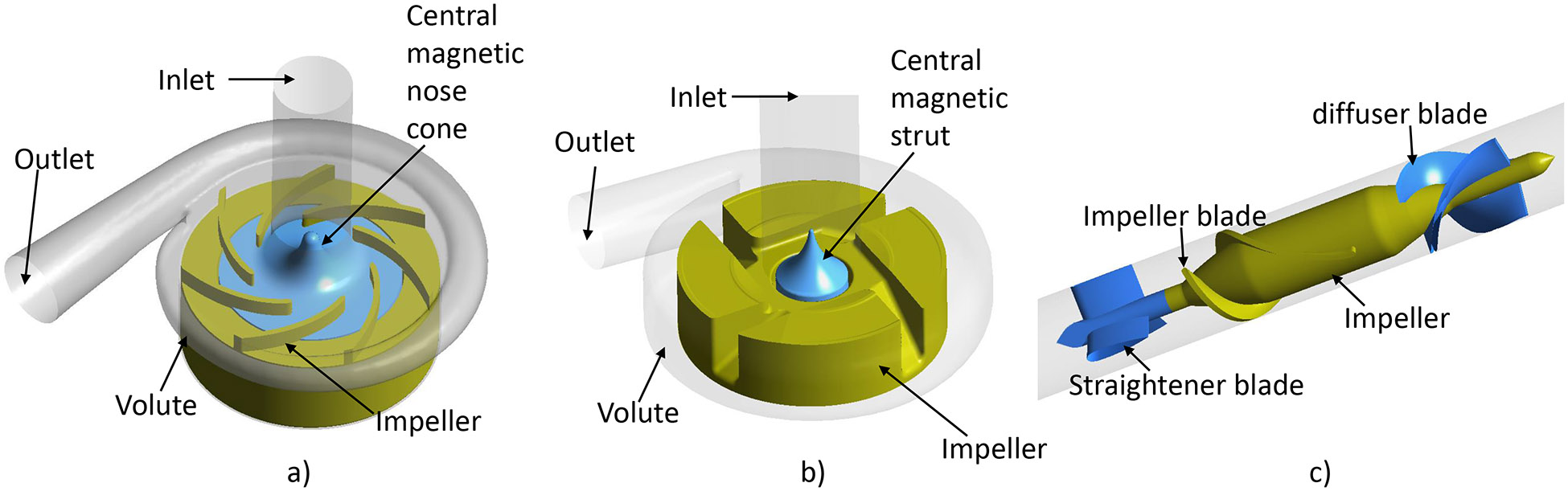
Schematic drawing of the flow domains of the a) CH-VAD, b) HVAD and c) HM II pumps (parts with brown color are the rotary components).
The technical features of the HVAD and HM II pumps have been extensively reported in the literature 21-23. The HVAD is a centrifugal blood pump featuring a four-blade impeller levitated by a hybrid hydrodynamic and magnetic bearing system (Fig. 1(b)). A secondary flow path exists in the gap between the rotating impeller and lower housing and the central magnetic strut. Similar to the CH-VAD pump, the central strut directs the primary flow from the axial inlet to the radial blade channels. Different from the CH-VAD, the secondary flow meets and mixes with the primary flow prior to the blade leading edges. The HVAD pump weighs 150 g with a displaced volume of 50 ml. It can deliver blood flow up to 10 LPM with the designed rotating speed between 1800 and 4000 RPM. The HM II is an axial flow pump wherein its impeller is supported with two ball-and-cup mechanical bearings (Fig. 1(c)). The HM II pump weighs 281 g with a displaced volume of 63 ml; it can deliver blood flow up to 10 LPM with the designed rotating speed between 8000 and 15,000 RPM.
The geometries of the three LVADs were obtained from computer aided drawing (CAD) files or constructed by measuring the actual device components through a reverse engineering procedure as previously described 24. The blood flow domains in these devices were extracted from the CAD files using Ansys Design modeler 19.0 (Ansys, Inc, Canonsburg, PA, USA).
Meshing
Both structured and unstructured mesh were used to reduce the computational time. The details of the meshing procedure can be found in previous publications 24, 25. Meshes in the regions with complex flow patterns and/or high shear stress were particularly refined; inflation layers were used in the regions adjacent to walls for more accurate prediction of boundary layers (Fig. 2). A mesh independence analysis was performed to ensure that the mesh quality was satisfied for the accuracy and convergence purpose. Specifically, coarse, medium and fine meshes were generated and flow was solved with the three meshes. The relative errors of the solved velocity fields of the three meshes were calculated. When the relative error between two meshes is less than 5%, further mesh refinement won’t increase accuracy much more; the finer mesh of the two is then selected for simulation. More details of the mesh independence analysis method can be found in our previous publication 25. The number of elements for the CH-VAD, HVAD, and HM II pumps were 10.7, 22.2, and 4.8 million, respectively. The HVAD pump had much more elements because of its extremely narrow gap between the impeller wedge surface and the upper housing (Fig. 2b).
Figure 2.
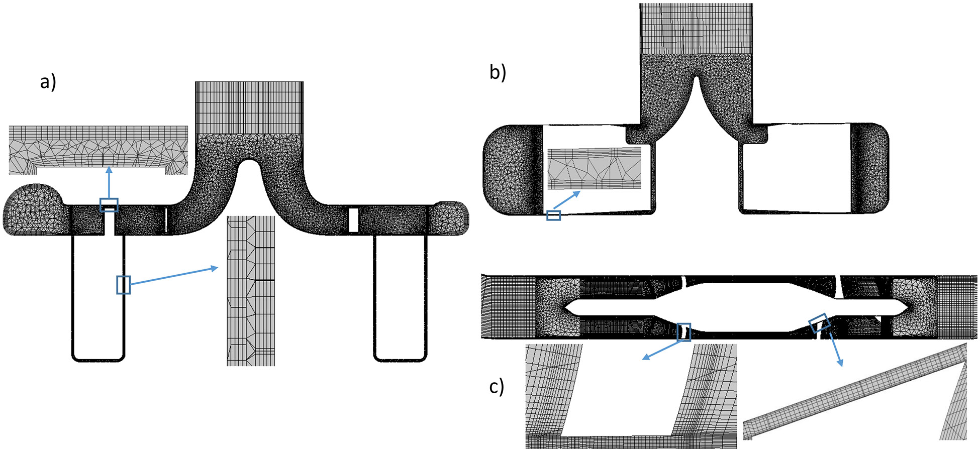
Mesh for the a) CH-VAD, b) HVAD and c) HM II pumps (represented with mesh on the mid-plane).
Numerical schemes and procedures
CFD simulations were conducted by using the commercial finite volume solver FLUENT 19.0 (ANSYS Inc, Canonsburg, PA). The rotational motion of the impeller was implemented using the multiple reference frame (MRF) approach. All walls were set to be no-slip and no-penetration. Blood was treated as a Newtonian fluid with a density of 1050 kg/m3 and viscosity of 3.5 cP. The SIMPLE pressure-velocity coupling method was used to solve all fluid governing equations with a 2nd order accuracy. The Menter’s Shear Stress Transport (SST) k-ω model with low Reynolds (Re) number corrections was used. Boundary conditions were (i) a constant flow at the inlet entrance, and (ii) zero pressure at the outlet exit. Gravity is not considered in the simulations. Based on the reported or suggested normal mean arterial pressure (MAP) for LVAD patients 26, 27, the flow rate of 4.5 L/min with a pressure head of 80 mmHg was selected as the normal operating condition. According to the definition of hypertension by INTERMACS (MAP > 110 mmHg), the flow rate of 4.5 L/min and the pressure head of 120 mmHg was selected as the hypertension condition 28. Impeller rotating speeds were then decided from previously reported pressure and flow rate (HQ) curves of the CH-VAD pump 29, HVAD and HM II pumps 30; the rotating speeds of the CH-VAD, HVAD and HM II pumps were 3000, 2800 and 10400 RPM for the normal operating condition and 3550, 3250 and 12300 RPM for the hypertension condition, respectively.
Analysis of shear stress and residence time
Non-physiological shear stress (NPSS) has been shown to cause damage to blood cells 31-34. Therefore, the viscous scalar shear stress (SSS) was derived from the simulated flow fields to represent NPSS in each pump according to the following formula:
| (1) |
where is the shear stress tensor and were calculated by multiplying the shear rate tensor, , with the blood viscosity.
The washout and estimate thrombosis potentials in the three pumps was estimated by the residential time, which was calculated with the Eulerian scalar transport approach:
| (2) |
where is the residential time of blood at each space point inside the pump. This formula is obtained by rewriting the time material derivative into the substantial derivative for fluid mechanics. Since the CH-VAD, HVAD and HM II pumps have different prime volumes and flow patterns, we used the normalized residential time to compare the washout among the three pumps. In details, the velocity-weighted residential time at the pump outlet was calculated () which represents the average time for blood to pass through the pump from the inlet to the outlet. The normalized residential time () was then calculated as . Bad washout regions could be identified by large .
Hemolytic performance
Hemolysis was calculated by using the Eulerian scalar transport approach. In this approach, the power law relationship between hemolysis index (HI) (the percentage change in plasma free hemoglobin (PFH) relative to the total hemoglobin) and scalar shear stress (SSS) and exposure time (t) was transformed first 22, 35, 36 by defining a new scalar variable . The change in HI’ was governed as:
| (3) |
where C (), α (=2.0639) and β (=0.2777) are empirical coefficients obtained through in-vitro experiments 37, and D is the diffusion coefficient of erythrocytes. Later, HI can be calculated as (HI’)β. The velocity-weighted average value of HI at the pump outlet represents the shear-induced hemolysis level of blood after one passage through the pump.
Results
Hemodynamic results
The simulated pressure heads (ΔP) of the CH-VAD, HVAD and HM II pumps were approximately 79, 83 and 79 mmHg the normal operating condition, and 117, 122 and 119 mmHg under the hypertension condition, respectively. The simulated ΔP values of the three pumps agree with the reported measurement under the same flow rate and rotational speed 29, 30. This indicates that the simulated results were correct.
Velocity fields
The central conical strut in the CH-VAD and HVAD pumps do help to navigate the axial flow from the inlet to the radial flow and smoothly enter the blade channels (Fig. 3 (a) and (b)). Blood is accelerated by impeller blades, and decelerated once it enters the volute. Due to the pressure difference between the volute and the blade leading edge, a small portion of the blood flows back and reenters the blade channels through the gaps between the impeller and the bottom housing and between the impeller and the central strut (secondary flow path). On the other hand, blood flows through the HM II pump axially (Fig. 3 (c)). Blood is accelerated by the blades while flowing through the blade-channels; the diffuser blades at downstream act like the volute to convert part of blood kinetic energy to potential energy (i.e. static pressure).
Figure 3.
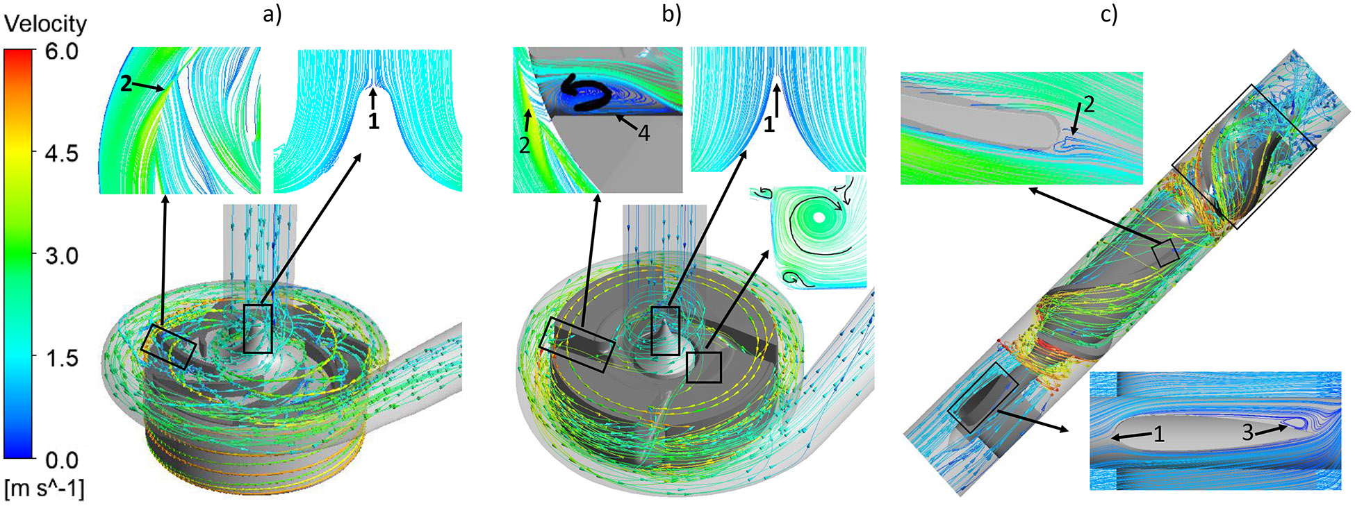
Typical streamlines of the relative velocity for the a) CH-VAD, b) HVAD and c) HM II pumps under the normal condition.
At the simulated normal operating condition, a stagnation point was observed at the tip of the conical strut in the CH-VAD and HVAD pumps (Fig. 3a and 3b, markers 1), while stagnation points in the HM II appeared at the leading edge of the three straighteners (Fig. 3c, marker 1). Areas of flow detachment were observed at the trailing edges of the impeller blades in all the three pumps (Fig 3, markers 2). For the HM II, areas of flow detachment were also found at the trailing edge of the three straighteners and the three diffuser vanes (Fig. 3c, markers 3). No detachment flow or strong recirculation was observed inside the blade channels of the CH-VAD and the HM II pumps while detachment appeared inside the blade channels of the HVAD pump (Fig. 3b, marker 4). Same stagnation points were observed in each pump under the hypertension condition as well (pictures not shown). The flow patterns were very similar between the two operating conditions for each pump.
Washing out
The average resident time ( at the outlet were 0.12 sec, 0.20 sec and 0.18 sec for the CH-VAD, HVAD and HM II pumps under the normal condition, respectively. For the HM II pump, over 99% of the volume had the normalized resident time () less than 1, while approximately 67% and 70% of the volume had less than 1 for the CH-VAD and HVAD pumps, respectively. The HM II pump (axial flow) had less secondary flow, resulting in a larger volume with compared to the CH-VAD and HVAD pumps (centrifugal flow). All the volume in the CH-VAD and HVAD pumps had less than 4 and 6, respectively, but a small percentage of the volume (~3x10⁻⁶ %) near the straighteners (Fig. 3c, markers 1 and 3) in the HM II pump had >20. This indicated that HM II pump might have elevated potential of thrombosis in that region. The values for the three pumps under hypertension condition were nearly the same as the normal condition. However, the volume with under the hypertension condition increased to more than 99% and 96% for the CH-VAD and HVAD pumps, respectively. The maximum normalized residential time of the blood in the CH-VAD and HVAD pumps mildly increased to approximately 6 and 9, indicating some regional recirculation was enhanced. There was no noticeable changes of for the blood flow inside the HM II pump under the hypertension condition.
Shear stresses
The wall shear stress (WSS) distribution on the impeller surface was compared among the three pumps. WSS was classified into three levels: 1) below 10Pa, which is considered in the physiological range of shear stress; 2) between 10 Pa and 100 Pa, which can cause high molecular weight (HMW) VWF degradation and platelet activation 38-40; 3) above 100Pa, which is in non-physiological shear stress range and could further induce significant hemolysis and platelet receptor shedding 33, 41. Fig. 4 shows the WSS contours on the impeller surface of the three pumps under the normal condition. The areas colored in red had WSS higher than 500 Pa. Hot spots (red) were noted at the leading edges and trailing edges of the CH-VAD pump impeller (Fig. 4a, markers I), at the wedge surface of the impeller of the HVAD pump (Fig. 4b, marker III), and at the impeller leading edges and the diffuser vane leading edges of the HM II pump (Fig 4c, markers I, II). The CH-VAD pump had noticeably lower levels of WSS on its impeller compared with the HVAD and HM II pumps. The area-weighted average WSS was 72.3 Pa, 94.2 Pa and 107.1 Pa for the CH-VAD, HVAD and HM II pumps, respectively. The WSS distribution under the hypertension condition was similar to the normal condition (Fig. 5). Because of the higher rotating speeds of the impellers, the areas on the impeller surface with high WSS (>100 Pa) increased under the hypertension condition. The area-weighted average WSS was 85.5 Pa, 112.7 Pa and 128.8 Pa for the CH-VAD, HVAD and HM II pumps, respectively. Table 1 summarized the percentage of the area with WSS larger than 100 and 500 Pa on impeller surface of the three pumps under the two operating conditions.
Figure 4.
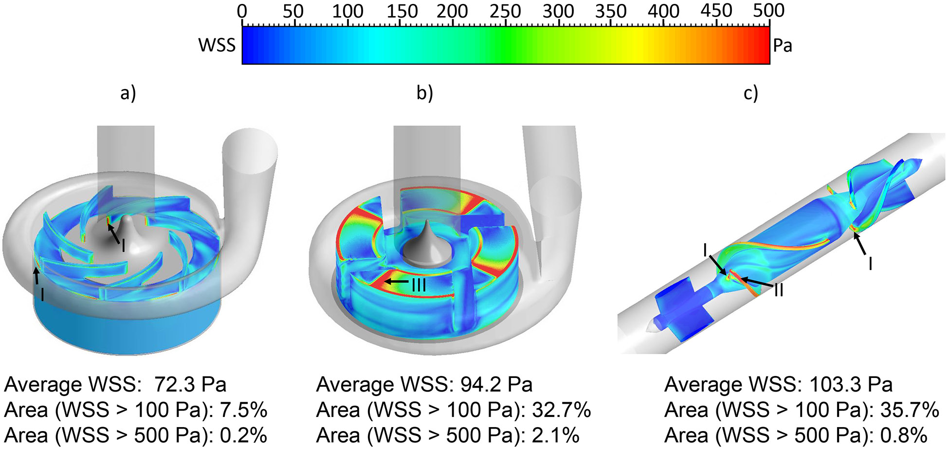
The wall shear stress (WSS) distribution on the impeller surface: a) CH-VAD, b) HVAD and c) HM II under the normal condition.
Figure 5.
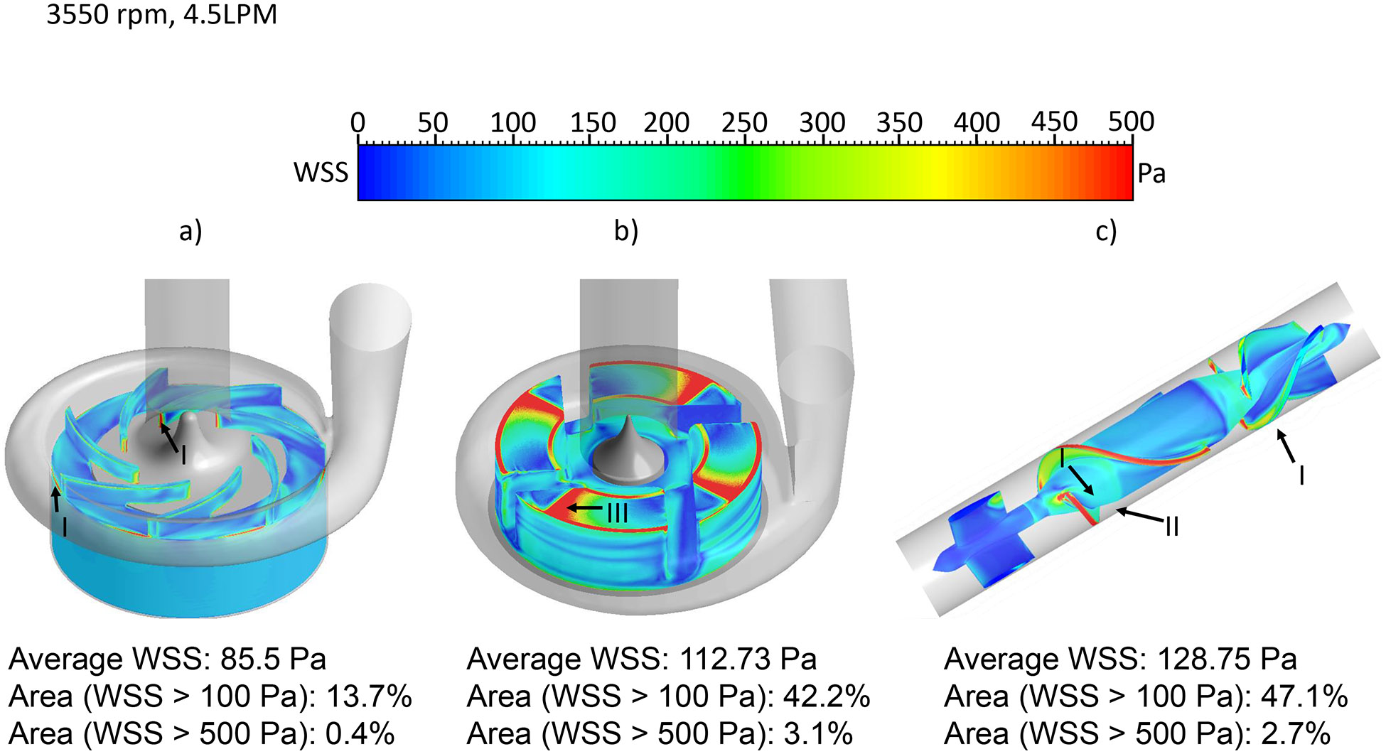
The wall shear stress (WSS) distribution on the impeller surface: a) CH-VAD, b) HVAD and c) HM II under the hypertension condition.
Table 1.
Summary of the WSS distribution
| Area (%) normal condition | Area (%) hypertension condition | |||||
|---|---|---|---|---|---|---|
| Stress (Pa) | CH-VAD | HVAD | HM II | CH-VAD | HVAD | HM II |
| >100 | 7.5 | 32.7 | 37.8 | 13.7 | 42.7 | 47.1 |
| >500 | 0.2 | 2.1 | 0.9 | 0.4 | 3.1 | 2.7 |
(Area in percentage of the total surface area).
The bulk SSS contours on the axial mid-plane and meridian plane across the impeller blade channels of the three pumps under the normal condition were shown in Fig. 6. The regions with high viscous shear stress were located at the leading edges, the trailing edges and in the small gaps of the secondary flow path for the three pumps. Particularly, high viscous shear stresses were present in the gap for the hydrodynamic bearing in the HVAD pump (Fig. 6b) and the leading edges of the diffuser blades in the HM II pump (Fig. 6c). Fig. 7 shows the scalar shear stress distribution inside the CH-VAD, HVAD and HM II pumps under the normal and hypertension conditions. The y axis shows the percentage of the volume with certain SSS levels relative to the total blood volume in the pump. It is worth to note that the CH-VAD pump has the lowest volume percentage with high SSS (>100 Pa) under both the normal and hypertension conditions among the three pumps. The volume with shear stress level higher than 100 Pa increased for all three pumps under the hypertension condition. Yet, most of the volume of the three pumps still experienced the shear stress levels less than 10 Pa. Table 2 summarized the percentage of the blood volume in each pump with the three shear stress levels: (1) below 10 Pa, (2) between 10 Pa and 100 Pa and (3) above 100 Pa under the normal and hypertension conditions.
Figure 6.

Scalar shear stress contours of the a) CH-VAD, b) HVAD and c) HM II pumps under the normal condition. The inserts show the regions with high shear stress.
Figure 7.
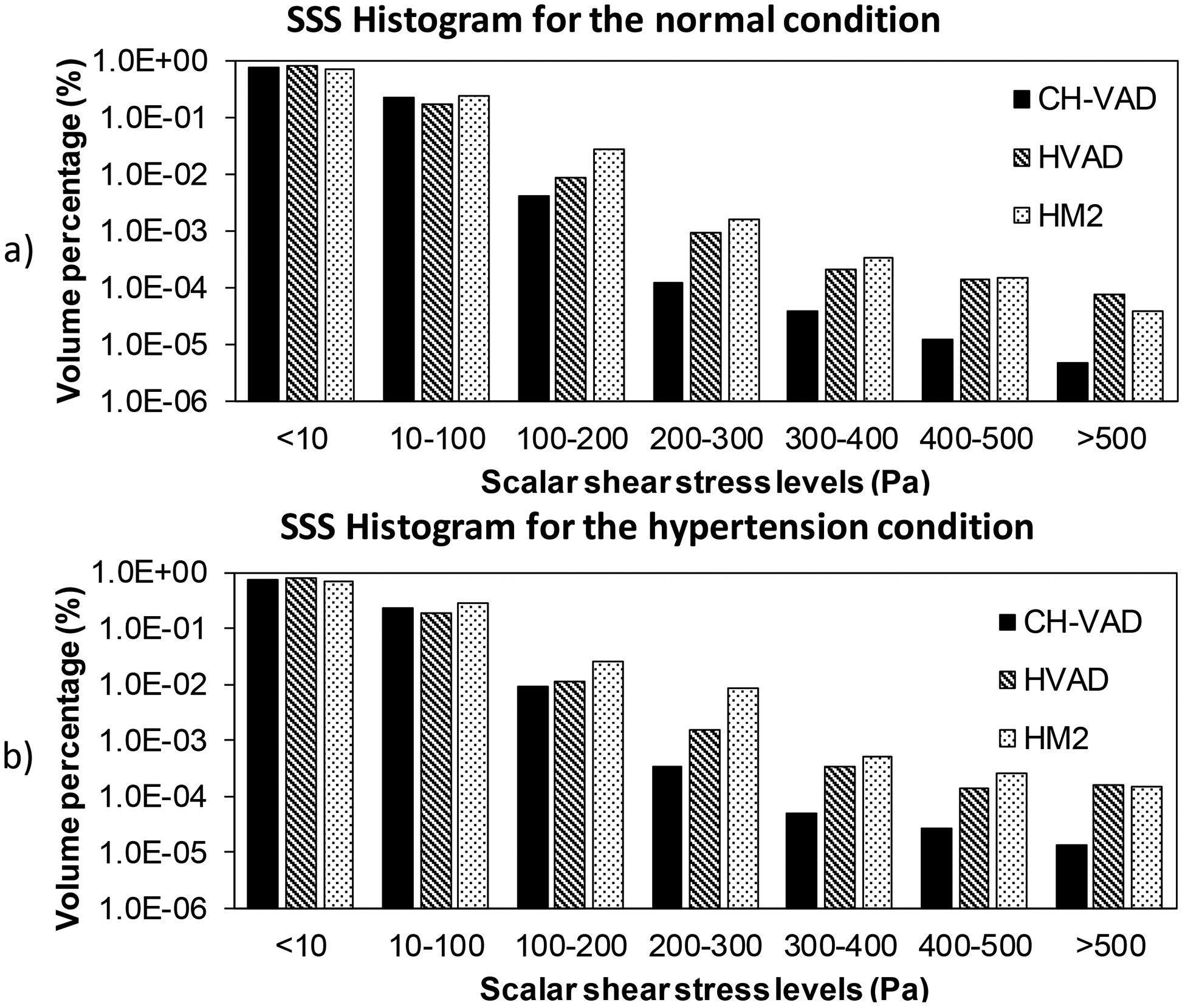
Scalar shear stress histograms of the three pumps under the a) normal and b) hypertension conditions in logarithm scale.
Table 2.
Summary of the bulk stress distribution
| Volume (%) normal condition | Volume (%) hypertension condition | |||||
|---|---|---|---|---|---|---|
| Stress (Pa) | CH-VAD | HVAD | HM II | CH-VAD | HVAD | HM II |
| <=10 | 77.3 | 81.8 | 73.2 | 76.0 | 79.6 | 69.2 |
| <100 | 99.6 | 99.0 | 97.1 | 99.1 | 98.6 | 96.66 |
| >=100 | 0.4 | 1.0 | 2.9 | 0.9 | 1.4 | 3.4 |
(Volume in percentage of the total prime volume).
Hemolytic Performance
Fig. 8 shows the HI contours on the axial mid-cut plane and meridian plane through blade channels of the three pumps under the normal condition. Areas with high HI (hot spots) indicated high PFH concentration; the high PFH concentration could be caused by local high shear stress and/or long exposure time. In the CH-VAD pump, areas with high HI were close to the leading edges and trailing edges of the blades and in the small gap of the U-shaped secondary flow path (Fig. 8a). In the HVAD pump, hot spots were observed in the narrow gap for the hydrodynamic bearing (insert of Fig. 8b) and in the four blade channels and the trailing edges (Fig. 8b). In the HM II pump, areas with high HI were found at the leading edge of the blades, near the diffuser blades and in the small gap between the top surface of the blades and housing (Fig. 8c). The velocity weighted average HI at the outlets of the CH-VAD, HVAD and HM II pumps under the normal condition were 4.3x10⁻⁴, 9.1x10⁻⁴ and 8.8x10⁻⁴, respectively. Regions with high HI were found at the same locations as the normal condition for the three pumps under the hypertension condition, while the size of the hot spots became bigger. The velocity weighted average HI at the outlets of the CH-VAD, HVAD and HM II pumps under the hypertension condition were 6.4x10⁻⁴, 11.9x10⁻⁴ and 14.1x10⁻⁴, respectively. The HI under the hypertension condition increased by about 50% compared to the normal condition.
Figure 8.
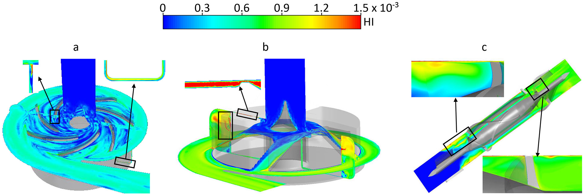
Hemolysis index (HI) contours on the mid plane and meridian plane of the a) CH-VAD, b) HVAD and 3) HM II pumps under the normal condition.
Discussion
The new fully maglev CH-VAD pump was numerically analyzed against the two FDA approved LVAD pumps (HVAD and HM II). The flow structures (high shear stress and low washout regions) and hemolysis inside the CH-VAD, HVAD and HM II pumps were assessed under two clinically relevant conditions of LVAD support (normal and hypertension). The CFD predicted HI of the CH-VAD pump was about two time smaller than those of the HVAD and HM II with similar pressure head and flow rate. This could be attributed to its flow path design which reduced flow detachment and recirculation. Flow detachment and recirculation were often associated with elevated shear stress and extended exposure time. The secondary flow in the CH-VAD pump met the primary flow inside the impeller blade channels where flow was well guided. This design avoided the head-to-head mixing of the secondary flow and the primary flow, which may possibly result in less flow detachment and recirculation. The hemolysis caused by the HVAD and HM II pumps were similar under the normal condition. This is consistent with a recent numerical simulation by Thamsen et. al. 42. CFD predicted a better hemolytic performance of the CH-VAD in this study, which was consistent with our previous experimental measurement under the normal condition 29.
Relatively short normalized residential time (i.e maximum < 6) was observed in the CH-VAD and HVAD pumps, which indicates good washout and low thrombosis potential. The good washout of the CH-VAD pump seemed to agree with previously published data that no device thrombosis was observed in 30 animal experiments 43. The long normalized residential time (i.e. > 20) in the regions of the straighteners in the HM II pump indicated a relatively elevated potential for thrombosis. This appeared to be consistent with the clinical observation of device thrombosis near the HM II straighteners and the adjacent bearing 9, 44-46. However, the residential time in this study didn’t incorporate the interaction of blood components with the device wall, and it didn’t provide confirmative information whether blood elements would adhere to adjacent walls.
LVAD with elevated afterload (hypertension) has been associated with increased risks of device thrombosis and stroke 17, 47. However, the pathophysiology behind the association is still unclear 28. The CFD simulation showed that the washout was similar under the hypertension and normal conditions for three pumps. Yet, bulk shear stress levels increased and more blood volume experienced SSS between 10 and 100 Pa under the hypertension condition, indicating elevated shear-induced platelet activation. The hemolysis levels increased by more than 30% under the hypertension condition. Hemolysis process is associated with increased activities of multiple coagulant factors, PFH induced platelet activation, and suppressed activity of nitric oxide 48, 49. The coagulant factors and activated platelets may accumulate in stagnation or low wash regions (i.e. bearing) and cause a local hypercoagulable state, attributing to device thrombosis.
The MRF approach was used in this study to approximate the rotation of the impellers. It is known that sliding mesh provides better accuracy than MRF. However, for steady flow simulations with constant impeller rotating speed and constant flow rate, the differences between the sliding mesh and MRF are small. Particularly, the differences of the average velocity, SSS and impeller WSS predicted with MRF and with sliding mesh were less than 5% for the CH-VAD and HM II pumps.
The CFD approach used in this study had certain shortages. Due to the small size of the gaps between the impeller and housing in the CH-VAD and HVAD, a small change in the impeller position could impact the shear stress field noticeably. Specifically, fast rotating impellers would experience significant hydrodynamic forces due to unbalanced fluid pressure on the impeller surface, resulting in a lifting force moving the impeller along the rotatory axis and a side loading force tilting the impeller. Additionally, the distribution of unbalanced pressure could change when the impeller moves, causing a periodic movement of the impeller. These movements could change the gap sizes, affect blood flow, and result in different shear stress levels and HI predictions. However, flow through the secondary flow path accounts for small amount of the total blood volume, and the effect may not be significant.
Moreover, the geometries of the HVAD and HM II pumps were reverse engineered by measuring the used physical pumps. The inaccuracies in the geometries of the HVAD and HM II pumps could impact the shear stress and hemolysis levels in the areas where the gap sizes are small. Specifically, the gap size of the hydrodynamic bearing in the HVAD is generally smaller than 0.05 mm 16, and the gap size between the blade tips and the housing in the HM II pump is 0.1 mm 50. Therefore, the inaccuracies in the geometries of the two pumps could potentially cause noticeable changes in the wall shear stress levels in these gaps. The CFD predicted HI in the areas with small gaps could also be impacted. However, blood flow volume through these gaps is relatively small compared with the primary flow. Therefore, the impact on global HI may not be significant.
Additionally, current turbulent models including the k-Ω SST used in this study could not capture complex flows such as detachment or separation flow 25. Therefore, CFD predicted SSS fields could be different from the real flow fields in the areas with complex flow.
Conclusion
This study provided characterization of the flow structures and hemocompatibility of the newly developed full maglev CH-VAD pump, and the FDA approved HVAD and HM II pumps under two clinical relative operating conditions (normal and hypertension). The study demonstrated that the washout in the CH-VAD pump is comparable to the HVAD and HM II pumps. The CH-VAD has significantly less area with WSS larger than 100 Pa and less bulk volume with SSS larger than 100 Pa compared to the HVAD and HM II pumps under the normal and hypertension conditions. The study suggested that the CH-VAD pump has better hemolytic biocompatibility than the HVAD and HM II pumps.
Acknowledgement
This work was funded by National Institutes of Health (grant numbers: 1R01 HL124170 and R01HL131750).
References
- 1.Benjamin EJ, Virani SS, Callaway CW, et al. Heart Disease and Stroke Statistics-2018 Update: A Report From the American Heart Association. Circulation. 2018; 137: e67–e492. [DOI] [PubMed] [Google Scholar]
- 2.Voigt J, Sasha John M, Taylor A, Krucoff M, Reynolds MR and Michael Gibson C. A reevaluation of the costs of heart failure and its implications for allocation of health resources in the United States. Clinical cardiology. 2014; 37: 312–21. [DOI] [PMC free article] [PubMed] [Google Scholar]
- 3.Rose EA, Moskowitz AJ, Packer M, et al. The REMATCH trial: rationale, design, and end points. Randomized Evaluation of Mechanical Assistance for the Treatment of Congestive Heart Failure. The Annals of thoracic surgery. 1999; 67: 723–30. [DOI] [PubMed] [Google Scholar]
- 4.Colvin M, Smith JM, Hadley N, et al. OPTN/SRTR 2016 Annual Data Report: Heart. American journal of transplantation : official journal of the American Society of Transplantation and the American Society of Transplant Surgeons. 2018; 18 Suppl 1: 291–362. [DOI] [PubMed] [Google Scholar]
- 5.Rodriguez LE, Suarez EE, Loebe M and Bruckner BA. Ventricular assist devices (VAD) therapy: new technology, new hope? Methodist DeBakey cardiovascular journal. 2013; 9: 32–7. [DOI] [PMC free article] [PubMed] [Google Scholar]
- 6.Rose EA, Gelijns AC, Moskowitz AJ, et al. Long-term use of a left ventricular assist device for end-stage heart failure. The New England journal of medicine. 2001; 345: 1435–43. [DOI] [PubMed] [Google Scholar]
- 7.Hanke JS, Rojas SV, Mahr C, et al. Five-year results of patients supported by HeartMate II: outcomes and adverse events. European journal of cardio-thoracic surgery : official journal of the European Association for Cardio-thoracic Surgery. 2017. [DOI] [PubMed] [Google Scholar]
- 8.Kirklin JK, Naftel DC, Pagani FD, et al. Seventh INTERMACS annual report: 15,000 patients and counting. The Journal of heart and lung transplantation : the official publication of the International Society for Heart Transplantation. 2015; 34: 1495–504. [DOI] [PubMed] [Google Scholar]
- 9.Mokadam NA, Andrus S and Ungerleider A. Thrombus formation in a HeartMate II. European journal of cardio-thoracic surgery : official journal of the European Association for Cardio-thoracic Surgery. 2011; 39: 414. [DOI] [PubMed] [Google Scholar]
- 10.Starling RC, Moazami N, Silvestry SC, et al. Unexpected abrupt increase in left ventricular assist device thrombosis. The New England journal of medicine. 2014; 370: 33–40. [DOI] [PubMed] [Google Scholar]
- 11.Saito S, Sakaguchi T, Miyagawa S, et al. Jarvik 2000 biventricular assist device conversion from old pin-shaped bearing pumps to new conical bearing pumps. Journal of artificial organs : the official journal of the Japanese Society for Artificial Organs. 2013; 16: 105–9. [DOI] [PubMed] [Google Scholar]
- 12.Fatullayev J, Samak M, Sabashnikov A, et al. Continuous-Flow Left Ventricular Assist Device Thrombosis: A Danger Foreseen is a Danger Avoided. Medical science monitor basic research. 2015; 21: 141–4. [DOI] [PMC free article] [PubMed] [Google Scholar]
- 13.Nojiri C, Kijima T, Maekawa J, et al. More than 1 year continuous operation of a centrifugal pump with a magnetically suspended impeller. ASAIO journal. 1997; 43: M548–52. [PubMed] [Google Scholar]
- 14.Olsen DB and Bramm G. Blood pump with a magnetically suspended impeller. Transactions - American Society for Artificial Internal Organs. 1985; 31: 395–401. [PubMed] [Google Scholar]
- 15.Akamatsu T, Nakazeki T and Itoh H. Centrifugal blood pump with a magnetically suspended impeller. Artificial organs. 1992; 16: 305–8. [DOI] [PubMed] [Google Scholar]
- 16.Thamsen B, Plamondon M, Granegger M, et al. Investigation of the Axial Gap Clearance in a Hydrodynamic-Passive Magnetically Levitated Rotary Blood Pump Using X-Ray Radiography. Artificial organs. 2018; 42: 510–5. [DOI] [PubMed] [Google Scholar]
- 17.Najjar SS, Slaughter MS, Pagani FD, et al. An analysis of pump thrombus events in patients in the HeartWare ADVANCE bridge to transplant and continued access protocol trial. The Journal of heart and lung transplantation : the official publication of the International Society for Heart Transplantation. 2014; 33: 23–34. [DOI] [PubMed] [Google Scholar]
- 18.Hanke JS, Dogan G, Zoch A, et al. One-year outcomes with the HeartMate 3 left ventricular assist device. The Journal of thoracic and cardiovascular surgery. 2018; 156: 662–9. [DOI] [PubMed] [Google Scholar]
- 19.Krabatsch T, Netuka I, Schmitto JD, et al. Heartmate 3 fully magnetically levitated left ventricular assist device for the treatment of advanced heart failure −1 year results from the Ce mark trial. Journal of cardiothoracic surgery. 2017; 12: 23. [DOI] [PMC free article] [PubMed] [Google Scholar]
- 20.Mehra MR, Goldstein DJ, Uriel N, et al. Two-Year Outcomes with a Magnetically Levitated Cardiac Pump in Heart Failure. The New England journal of medicine. 2018; 378: 1386–95. [DOI] [PubMed] [Google Scholar]
- 21.Wu ZJ, Antaki JF, Burgreen GW, Butler KC, Thomas DC and Griffith BP. Fluid dynamic characterization of operating conditions for continuous flow blood pumps. ASAIO journal. 1999; 45: 442–9. [DOI] [PubMed] [Google Scholar]
- 22.Chen Z, Jena SK, Giridharan GA, et al. Flow features and device-induced blood trauma in CF-VADs under a pulsatile blood flow condition: A CFD comparative study. International journal for numerical methods in biomedical engineering. 2018; 34. [DOI] [PMC free article] [PubMed] [Google Scholar]
- 23.Tuzun E, Roberts K, Cohn WE, et al. In vivo evaluation of the HeartWare centrifugal ventricular assist device. Texas Heart Institute journal. 2007; 34: 406–11. [PMC free article] [PubMed] [Google Scholar]
- 24.Fraser KH, Zhang T, Taskin ME, Griffith BP and Wu ZJ. A quantitative comparison of mechanical blood damage parameters in rotary ventricular assist devices: shear stress, exposure time and hemolysis index. Journal of biomechanical engineering. 2012; 134: 081002. [DOI] [PMC free article] [PubMed] [Google Scholar]
- 25.Zhang J, Zhang P, Fraser KH, Griffith BP and Wu ZJ. Comparison and experimental validation of fluid dynamic numerical models for a clinical ventricular assist device. Artificial organs. 2013; 37: 380–9. [DOI] [PMC free article] [PubMed] [Google Scholar]
- 26.Slaughter MS, Pagani FD, Rogers JG, et al. Clinical management of continuous-flow left ventricular assist devices in advanced heart failure. The Journal of heart and lung transplantation : the official publication of the International Society for Heart Transplantation. 2010; 29: S1–39. [DOI] [PubMed] [Google Scholar]
- 27.Wilson SR, Givertz MM, Stewart GC and Mudge GH, Jr. Ventricular assist devices the challenges of outpatient management. Journal of the American College of Cardiology. 2009; 54: 1647–59. [DOI] [PubMed] [Google Scholar]
- 28.Bennett MK and Adatya S. Blood pressure management in mechanical circulatory support. Journal of thoracic disease. 2015; 7: 2125–8. [DOI] [PMC free article] [PubMed] [Google Scholar]
- 29.Berk ZBK, Zhang J, Chen Z, Tran D, Griffith BP and Wu ZJ. Evaluation of in vitro hemolysis and platelet activation of a newly developed maglev LVAD and two clinically used LVADs with human blood. Artificial organs. 2019. [DOI] [PMC free article] [PubMed] [Google Scholar]
- 30.Noor MR, Ho CH, Parker KH, Simon AR, Banner NR and Bowles CT. Investigation of the Characteristics of HeartWare HVAD and Thoratec HeartMate II Under Steady and Pulsatile Flow Conditions. Artificial organs. 2016; 40: 549–60. [DOI] [PubMed] [Google Scholar]
- 31.Chen Z, Koenig S, Slaughter M, Griffith B, Wu Z Quantitative Characterization of Shear-Induced Platelet Receptor Shedding: Glycoprotein Ibα, Glycoprotein VI and Glycoprotein IIb/IIIa. ASAIO J 2017. Nov 7 doi: 101097/MAT0000000000000722 [Epub ahead of print]. [DOI] [PMC free article] [PubMed] [Google Scholar]
- 32.Chen Z, Mondal NK, Ding J, Gao J, Griffith BP and Wu ZJ. Shear-induced platelet receptor shedding by non-physiological high shear stress with short exposure time: glycoprotein Ibalpha and glycoprotein VI. Thromb Res. 2015; 135: 692–8. [DOI] [PMC free article] [PubMed] [Google Scholar]
- 33.Chen Z, Mondal NK, Ding J, Koenig SC, Slaughter MS and Wu ZJ. Paradoxical Effect of Nonphysiological Shear Stress on Platelets and von Willebrand Factor. Artificial organs. 2016; 40: 659–68. [DOI] [PMC free article] [PubMed] [Google Scholar]
- 34.Ding J, Chen Z, Niu S, et al. Quantification of Shear-Induced Platelet Activation: High Shear Stresses for Short Exposure Time. Artif Organs. 2015; 39 795–802. [DOI] [PubMed] [Google Scholar]
- 35.Farinas MI, Garon A, Lacasse D and N'Dri D. Asymptotically consistent numerical approximation of hemolysis. Journal of biomechanical engineering. 2006; 128: 688–96. [DOI] [PubMed] [Google Scholar]
- 36.Taskin ME, Fraser KH, Zhang T, Wu C, Griffith BP and Wu ZJ. Evaluation of Eulerian and Lagrangian models for hemolysis estimation. ASAIO journal. 2012; 58: 363–72. [DOI] [PubMed] [Google Scholar]
- 37.Ding J, Niu S, Chen Z, Zhang T, Griffith BP and Wu ZJ. Shear-Induced Hemolysis: Species Differences. Artificial organs. 2015; 39: 795–802. [DOI] [PubMed] [Google Scholar]
- 38.Di Stasio E and De Cristofaro R. The effect of shear stress on protein conformation: Physical forces operating on biochemical systems: The case of von Willebrand factor. Biophysical chemistry. 2010; 153: 1–8. [DOI] [PubMed] [Google Scholar]
- 39.Schneider SW, Nuschele S, Wixforth A, et al. Shear-induced unfolding triggers adhesion of von Willebrand factor fibers. Proceedings of the National Academy of Sciences of the United States of America. 2007; 104: 7899–903. [DOI] [PMC free article] [PubMed] [Google Scholar]
- 40.Lippok S, Radtke M, Obser T, et al. Shear-Induced Unfolding and Enzymatic Cleavage of Full-Length VWF Multimers. Biophysical journal. 2016; 110: 545–54. [DOI] [PMC free article] [PubMed] [Google Scholar]
- 41.Horobin JT, Sabapathy S and Simmonds MJ. Repetitive Supra-Physiological Shear Stress Impairs Red Blood Cell Deformability and Induces Hemolysis. Artificial organs. 2017; 41: 1017–25. [DOI] [PubMed] [Google Scholar]
- 42.Thamsen B, Blumel B, Schaller J, et al. Numerical Analysis of Blood Damage Potential of the HeartMate II and HeartWare HVAD Rotary Blood Pumps. Artificial organs. 2015; 39: 651–9. [DOI] [PubMed] [Google Scholar]
- 43.Wu Y, Zhu LF and Luo Y. Development and current clinical application of ventricular assist devices in China. Journal of Zhejiang University Science B. 2017; 18: 934–45. [DOI] [PMC free article] [PubMed] [Google Scholar]
- 44.Meyer AL, Kuehn C, Weidemann J, et al. Thrombus formation in a HeartMate II left ventricular assist device. The Journal of thoracic and cardiovascular surgery. 2008; 135: 203–4. [DOI] [PubMed] [Google Scholar]
- 45.Capoccia M, Bowles CT, Sabashnikov A and Simon A. Recurrent Early Thrombus Formation in HeartMate II Left Ventricular Assist Device. Journal of investigative medicine high impact case reports. 2013; 1: 2324709613490676. [DOI] [PMC free article] [PubMed] [Google Scholar]
- 46.Bhamidipati CM, Ailawadi G, Bergin J and Kern JA. Early thrombus in a HeartMate II left ventricular assist device: a potential cause of hemolysis and diagnostic dilemma. The Journal of thoracic and cardiovascular surgery. 2010; 140: e7–8. [DOI] [PMC free article] [PubMed] [Google Scholar]
- 47.Nassif ME, Tibrewala A, Raymer DS, et al. Systolic blood pressure on discharge after left ventricular assist device insertion is associated with subsequent stroke. The Journal of heart and lung transplantation : the official publication of the International Society for Heart Transplantation. 2015; 34: 503–8. [DOI] [PMC free article] [PubMed] [Google Scholar]
- 48.Ataga KI. Hypercoagulability and thrombotic complications in hemolytic anemias. Haematologica. 2009; 94: 1481–4. [DOI] [PMC free article] [PubMed] [Google Scholar]
- 49.Villagra J, Shiva S, Hunter LA, Machado RF, Gladwin MT and Kato GJ. Platelet activation in patients with sickle disease, hemolysis-associated pulmonary hypertension, and nitric oxide scavenging by cell-free hemoglobin. Blood. 2007; 110: 2166–72. [DOI] [PMC free article] [PubMed] [Google Scholar]
- 50.Schule CY, Thamsen B, Blumel B, et al. Experimental and Numerical Investigation of an Axial Rotary Blood Pump. Artificial organs. 2016; 40: E192–E202. [DOI] [PubMed] [Google Scholar]