

Abstract
The selective photoreduction of CO2 in aqueous media based on earth-abundant elements only, is today a challenging topic. Here we present the anchoring of discrete molecular catalysts on organic polymeric semiconductors via covalent bonding, generating molecular hybrid materials with well-defined active sites for CO2 photoreduction, exclusively to CO in purely aqueous media. The molecular catalysts are based on aryl substituted Co phthalocyanines that can be coordinated by dangling pyridyl attached to a polymeric covalent triazine framework that acts as a light absorber. This generates a molecular hybrid material that efficiently and selectively achieves the photoreduction of CO2 to CO in KHCO3 aqueous buffer, giving high yields in the range of 22 mmol g−1 (458 μmol g−1 h−1) and turnover numbers above 550 in 48 h, with no deactivation and no detectable H2. The electron transfer mechanism for the activation of the catalyst is proposed based on the combined results from time-resolved fluorescence spectroscopy, in situ spectroscopies and quantum chemical calculations.
Subject terms: Photocatalysis, Supramolecular polymers, Photocatalysis
The selective CO2 photoreduction in water mediated by earth-abundant photocatalysts remains highly challenging. Here the authors present the coordinative anchorage of molecular catalysts on a pyridine-armed covalent triazine framework for CO2 photoreduction to CO in fully aqueous solutions.
Introduction
Sunlight-driven reduction of CO2 to carbon-containing products is a promising strategy to mitigate the greenhouse effect by constructing a carbon-neutral cycle, where CO2 is utilized as a feedstock for synthons or to produce renewable energy, thus replacing fossil fuels1–3. Because of the inert nature of CO2 and strong competition from H2 evolution, extensive research efforts have been concentrated on the design of light-driven catalytic systems for CO2 reduction in a rapid and selective manner4–7.
Organic polymeric semiconductors like carbon nitrides (CNx)8, covalent triazine frameworks (CTFs)9, covalent organic frameworks (COFs)10, etc., constitute a promising type of photocatalysts with broad design flexibility due to their molecular nature. With the right choice and well-defined structures, organic polymeric semiconductors can be as durable, recyclable, and scalable as those inorganic ones. Further, by combining the merits of molecular and material science, new hybrid molecular materials can be prepared with superior performances11. Additionally, they can be based on earth-abundant and non-toxic metals, which make them highly attractive for solar fuels production8,12. In terms of CO2 photoreduction, however, most organic polymeric semiconductors still suffer from the absence of catalytic active sites. Hence, their surface electron will inevitably be used for direct reduction of CO2 to CO2·−, which demands high negative potentials up to −1.9 V vs. NHE (normal hydrogen electrode unless otherwise stated, at pH 7.0) under standard conditions13. Thus, the presence of a CO2 reduction catalyst combined with the organic semiconductor can potentially overcome the challenges of severe charge recombination and ultimately lead to high activity and selectivity14,15, as well as potentially circumvent the photodegradation issue during photocatalysis, which leads to false identification of carbonaceous products3,16–18.
With these considerations in mind, based on organic polymeric semiconductors, non-noble-metal-based molecular CO2 reduction catalysts19,20 based on earth-abundant elements include Co macrocycles14, metal porphyrins21,22, Co/Fe quaterpyridine complexes23,24, some of which have been reported to achieve turnover numbers (TONs) in the range of 103 for selective CO2 photoreduction to CO or formate. Very recently, a Ni-tris-2,2’-bipyridine complex, [Ni(bpy)3]2+, coupled with a semiconducting COF, was reported to show fast CO2 photoreduction to CO in MeCN/TEOA/H2O (6:2:2) solutions with an overall CO yield of 2.9 mmol g−1 25, nonetheless showing a moderate selectivity of 88%. However, in most cases the work is performed in organic solvents that are not useful for practical applications where aqueous medium is a must26–28. In contrast, the documented systems in fully aqueous solutions are quite rare. For example, besides the ones using noble-metal molecular catalysts20,29, an iron porphyrin, FeTCPP (=chloro FeIII tetra(4-carboxylphenyl)porphyrin) immobilized on modified CNx was reported30 as a noble-metal-free system for CO2 photoreduction to CO in aqueous TEOA solutions. However, a low selectivity of 68% and a TON < 1 is reported and thus serves more as a proof of concept than a robust catalytic system. One more instance is the anchorage of a carboxyl-derived cobalt quaterpyridine catalyst on poly(triazine-imide) lithium chloride (PTI-LiCl) as a type of crystalline CNx for photocatalytic CO2-to-CO conversion in 0.5 M KHCO3 solution with Na2SO3 as the sacrificial electron donor31. This molecular hybrid affords efficient CO yield up to 3.86 mmol g−1 with a selectivity of 96%, but only under strong UV irradiation at 390 nm rather than sunlight/visible light. The above limitations reveal the key challenges in constructing organic semiconductor-based molecular systems for high-performance CO2 photoreduction in fully aqueous systems.
To overcome these challenges, the judicious design of the organic polymeric semiconductors and molecular catalysts, along with their anchoring strategy, is crucial. All these factors can be fine-tuned and will determine the degree of electronic communication and interfacial electron transfer kinetics that, in turn, will be the key to their overall performance. In this context, the molecular nature of the catalysts bonded by coordinative, covalent bonds to organic semiconductors represents a step forward in the field that can lead to highly homogeneous dispersion with well-defined reactivity that will not suffer aggregation processes. Moreover, the easy modification of the molecular catalyst by ligand design allows the fine-tuning of both the thermodynamic and kinetic properties of the catalytic reaction, giving this type of system a high versatility to be adequately combined with organic semiconductors, thus providing systems with high apparent quantum yields (AQYs). However, the post-synthetic coordination anchorage has seldom been reported before in designing molecular hybrid photocatalysts for CO2 photoreduction with organic polymeric semiconductors.
Here we report a bottom-up approach to synthesize a CTF-based photocatalyst with dangling pyridine arms (p-CTF-py), which can provide the means for a covalent, coordinative binding of cobalt macrocyclic catalysts and the semiconductor, representing the rare example combining CTFs and molecular catalysts for selective CO2 photoreduction in fully aqueous solutions. The optimal molecular hybrid photocatalyst based on p-CTF-py can accomplish a high CO yield of 22.1 ± 0.8 mmol g−1 and a TON of 559 ± 20 during 48 h of simulated sunlight irradiation with no H2 evolution (~100% CO selectivity) and deactivation.
Results
Synthesis and characterization of CTF-based materials with immobilization of molecular catalysts
The terphenyl-based monomers, [1,1’:4’,1”-terphenyl]-4,4”-dicarbonitrile (M) and 2’-(2-(pyridin-4-yl)ethyl)-[1,1’:4’,1”-terphenyl]-4,4”-dicarbonitrile (M-py; see Fig. 1A for a drawing) were prepared in good yields (see Experimental section for details). Treatment of these monomers with polyphosphoric acid at 400 °C under vacuum promotes their polymerization via the formation of triazine units32 generating the polymeric materials p-CTF and p-CTF-py, respectively (Fig. 1A; see SI for details).
Fig. 1. Synthesis and characterization.

A Synthetic scheme for the amorphous p-CTF-py and CoXPc@p-CTF-py. B SEM and C TEM images with Fourier transformed pattern (Inset in C) of p-CTF-py. D EDS mapping of CoTCPc@p-CTF-py. E Normalized Co K-edge XANES and F Fourier transforms of k2-weighted Co EXAFS results of CoTCPc (blue) and CoTCPc@p-CTF-py (orange). Inset in E: (i) experimental zoom-in of the pre-edge region; (II) simulated Co K-edge pre-edge and rising edge XANES showing the increase in the pre-edge intensity and decrease of the 1 s→4pz transition in CoTCPc@p-CTF-py (orange) relative to CoTCPc (blue). Inset in F: DFT-calculated structure of CoTCPc@p-CTF-py with unpaired spin density plots. Source data are provided as a Source Data file.
In contrast to the reported crystalline CTF materials synthesized via similar methods with the phenyl- or biphenyl-based monomers32, p-CTF and p-CTF-py are amorphous solids as revealed by powder X-ray diffraction (Fig. S1). Consequently, the real structure of the as-prepared CTF samples should be more disordered than the anticipated structure drawn in Fig. 1A. The chemical compositions of the two CTF-based materials were also characterized by FT-IR (Figs. S2 and S3), solid-state 13C NMR (Fig. S4) and X-ray photoelectron spectroscopy (XPS; Figs. S5 and S6), confirming the successful preparation of the polymeric CTF materials. Their morphologies were examined via scanning electron microscopy (SEM; Figs. 1B and S7) and transmission electron microscopy (TEM; Figs. 1C and S8), where both CTF-based materials consist of stacked, wrinkled, amorphous sheets. The uneven surface and feathery nature of the CTF particles possibly originate from the abundant gas release during thermal synthesis32. In addition, their N2 sorption isotherms (Fig. S9A) reveal nearly three times larger specific surface area of p-CTF-py over that of p-CTF (66.7 vs. 23.4 cm2 g−1). This might be attributed to the emergence of additional pores produced by the dangling pyridyl arms intercalated between the layers of p-CTF-py. The effects of the dangling groups within the organic frameworks have been extensively utilized to tune the interlayer distances and pore volumes33,34. The above assumption is also consistent with a larger number of small pores of ca. 1.2 nm in the layers of p-CTF-py than in those of p-CTF, as revealed by the pore size distribution analysis (Fig. S9B). Additionally, both samples possess pores with sizes around 2.6 and 2.7 nm for p-CTF-py and p-CTF (Fig. S9B), respectively, consistent with the expected hexagon channels of the CTF structures.
We also evaluated the band energies of p-CTF-py and p-CTF by UV–vis diffuse reflectance spectroscopy (UV–vis-DRS; Figure S10) and Mott-Schottky plots (Fig. S11), exhibiting large bandgaps (2.57 and 3.20 eV) as well as flat-band-approximated conduction band (CB) potentials of −1.15 and −1.03 V vs. NHE, which have the sufficient thermodynamic driving force for the reduction of CO2 to CO (−0.52 V).
Next, four cobalt phthalocyanine derivatives, including cobalt phthalocyanine (CoPc), cobalt tetra-amino phthalocyanine (CoTAPc), cobalt perfluorinated phthalocyanine (CoFPc) and cobalt tetra-carboxyl phthalocyanine (CoTCPc; See Fig. 1A for a drawing of their structures) were immobilized on p-CTF-py by dispersing 10 mg of the latter in 1 mL of 1.0 mM solution of the Co catalyst and left stirring for 1 day at RT. The formed molecular hybrid materials, CoXPc@p-CTF-py (X = Ø meaning no substitution, F, TA, TC) were isolated by centrifugation and washed twice with DMF and water (Fig. 1A; see SI for details). During the immobilization process, the initial solutions decolorated roughly up to 60% for X = Ø, F, TA and up to 85% for X = TC (Fig. S12) as indicated by UV–vis spectroscopy. A similar strategy was used for the anchoring of CoTCPc in p-CTF, not containing the dangling pyridyl group, producing a decoloration of only 45%. All these results suggest that in the presence of the pyridyl group, the main interaction of the molecular catalysts with the CTF absorber occurs by the formation of a covalent Co-N bond with additional supramolecular stabilization involving CH-π and π-π interactions. This is further supported by calculations at the MN1535 level of theory (see Supplementary Information for further details), indicating that the coordination of CoTCPc to p-CTF-py is favored significantly (ΔE = 10.7 kcal/mol) over adsorption via supramolecular CH-π and π-π interactions (Fig. S13).
The presence of the molecular catalyst anchored on the CTF absorber was confirmed by inductively coupled plasma mass spectrometry (ICP-MS) which gives a loading in the range of 0.19–0.23% of Co per gram of material (30–40 nmols g−1; Table S1) and additionally supported by IR spectroscopy (Figs. S2 and S3). Further, energy-dispersive X-ray spectroscopy (EDS; Figs. 1D and S14) shows that cobalt is homogeneously distributed on each of the CoTCPc-loaded materials. The cross-sectional analysis of the cobalt element on CoTCPc@p-CTF-py further demonstrates that the Co complex is homogeneously dispersed into the CTF particles rather than mainly distributed on the surface (Fig. S15). The substantial dispersion is presumably endowed by the aforementioned uneven surface and feathery nature of the CTF particles. The TEM images (Figs. S16 and S17) of both molecular hybrid photocatalysts show negligible morphological changes compared to the bare CTF materials.
The cobalt valence state of CoTCPc and the effect of the bonding between CoTCPc and the CTF materials were examined by XPS where all the CTF-based materials display the C and N elements (Figs. S5 and S6) while additional Co 2p signals can be observed for CoTCPc@p-CTF-py and CoTCPc@p-CTF (Fig. S18). More importantly, the Co 2p binding energy of CoTCPc@p-CTF-py shows a more positive shift than that of CoTCPc (0.5 vs. 0.3 eV) associated with the Co-Npyr covalent bond36.
Additional characterization of this hybrid material was carried out by X-ray absorption near edge structure (XANES) and extended X-ray absorption fine structure (EXAFS) for CoTCPc@p-CTF-py and for the CoTCPc reference (blue) (Figs. 1E, F and S19). As shown in Fig. 1E, the Co K-edge XANES of CoTCPc displays a pre-edge peak at 7710.4 eV with an area of 7 units (Fig. 1E, inset (i), Fig. S19 and Table S2) together with a prominent shoulder at 7716.7 eV which corresponds to the 1 s→4pz transition and reflects the nature of the 4pz orbital in its square planar environment37,38. In contrast, CoTCPc@p-CTF-py exhibits a slightly more intense pre-edge peak at 7709.0 and 7710.8 eV with an area of 8.1 units (Fig. 1E inset (i), Figure S20, Table S2) as well as a weaker broadened 1 s → 4pz peak at 7715.7 eV. Both the increased pre-edge intensity as well as the broadened 1s→4pz peak of CoTCPc@p-CTF-py are due to an increase of its Co coordination number and distortion of the local geometry as supported by time-dependent DFT in XANES simulations (Fig. 1E inset (II)). As previously reported, the features in the pre-edge region have been shown to be particularly sensitive to the geometry39,40. Indeed non-centrosymmetric complexes display an increased intensity in their pre-edge features due to an increase in the metal 4p mixing into the 3 d orbitals contributing towards the electric dipole 1 s to 4p character of this transition40. CoTCPc@p-CTF-py with its increased distorted structural conformation, thus illustrates a slightly larger pre-edge than CoTCPc. The 1 s→4pz transition moreover reflects the coordination environment of the Co complexes as previously elaborated37,38. A change in the coordination geometry of the Co center in CoTCPc@p-CTF-py hereby leads to a greater delocalization of the metal 4p orbitals41,42 resulting in a lesser intense and broadened 1 s→4pz transition feature (Fig. 1E).
EXAFS studies were further carried out to extract structural information of the Co molecular catalyst before and after coordination to the CTF absorber (Fig. 1F). A prominent peak I is observed in the EXAFS spectra corresponding to the averaged contribution of the Co-N coordination. Analysis of the EXAFS spectrum for CoTCPc reveals the best fits with four Co-N distances of 1.90 Å whereas CoTCPc@p-CTF-py displays an increase in the amplitude of peak I together with the best fit involving five Co-N distances at 1.91 Å (Fig. S20 and Table S3), in agreement with their DFT optimized structures (Fig. 1F inset and Table S4).
Photocatalytic CO2 reduction
Photocatalytic experiments for the reduction of CO2 were carried out in a home-made 8 mL quartz vessel in which 0.5 mg of the molecular hybrid photocatalysts CoXPc@p-CTF-py were suspended in a 1.5 mL aqueous solution (0.33 g L−1) of 0.1 M KHCO3 containing 25 mM ascorbic acid (H2Asc, deprotonated to HAsc- by KHCO3) under 1 atm CO2. Then the suspension was irradiated under continuous stirring with AM 1.5 G light at 300 mW cm−2 for 48 h.
All the molecular hybrid photocatalysts show considerable activity for CO2 photoreduction to CO (>99% selectivity) in water with negligible formation of hydrogen and liquid products (Figs. 2 and S21–23 and Table 1, Entries 1–5), representing the rare example combining CTFs and molecular catalysts for selective CO2 photoreduction in fully aqueous solutions. The very high selectivity is mainly attributed to the excellent intrinsic performances of cobalt phthalocyanine catalysts43–47. Among them, CoTCPc@p-CTF-py exhibits the highest CO yield of 22.1 ± 0.8 mmol g−1 and TON of 559 ± 20 during 48 h, consistent with a production rate of 458 ± 17 μmol g−1 h−1. The best performance of CoTCPc@p-CTF-py can be partially attributed to the higher loading of the molecular catalyst along with increasing electron-withdrawing abilities of the functional groups48,49 on the CoXPc backbone (Figs. 2A and S22 and Table 1, Entries 1–4), suggesting that the carboxyl groups also contribute to the improved activity. Our previous studies50 have demonstrated the electronic effects of the varied substituents by cyclic voltammetry in homogeneous phase and theoretical calculations. We found that with increasingly electron-withdrawing groups on the Co complexes, the CoII/I redox potential became more positive, and the calculated Hirshfeld Co atomic charges increased, mandating lower overpotentials for catalytic CO2 reduction with CoTCPc being the optimal catalyst studied. This is indeed further confirmed by the parallel systems with p-CTF loaded with each of the four Co catalysts, where CoTCPc@p-CTF also displayed the highest CO yield (Fig. S23 and Table 1, Entries 5–8).
Fig. 2. CO2 photoreduction.
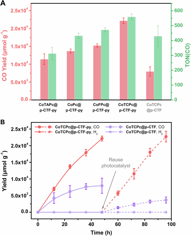
A Comparison of CO yields and TONs among the molecular hybrid photocatalysts. B Time profiles of photocatalytic CO (circle) and H2 (star) formation using CoTCPc@p-CTF-py (red) and CoTCPc@p-CTF (violet). After the first run of 48 h photocatalysis (solid lines), the colloidal photocatalyst was reused for the second run (dashed lines). General conditions: 0.33 g L−1 photocatalyst, 0.1 M KHCO3, 25 mM H2Asc, 300 mW cm−2 Xe lamp with AM 1.5 G filter, 1 atm CO2, 25 °C, 5 × 2 mm stir bar at 1000 rpm. The experimental error bars represent the standard deviations of three independent measurements. Source data are provided as a Source Data file.
Table 1.
Performance comparison
| Entry | Catalyst | Medium | Mol Catb (μmol g−1) | Sacrificial reagent (concentration) | CO yield (mmol g−1) | H2 yield (μmol g−1) | TON(CO)c | Maximum AQY | CO% |
|---|---|---|---|---|---|---|---|---|---|
| 1 | CoTCPc@p-CTF-py | 0.1 M KHCO3 | 39.6 | HAsc- (25 mM) | 22.1 ± 0.8 | n.d. | 1118 (559 ± 20 in each 2 runs) | 0.25 ± 0.06% at 395 nm0.12 ± 0.03% at 405 nm 0.04 ± 0.01% at 425 nm | 100% |
| 2 | CoFPc@p-CTF-py | 32.2 | 15.2 ± 0.5 | n.d. | 472 ± 14 | n.a. | 100% | ||
| 3 | CoPc@p-CTF-py | 31.6 | 13.7 ± 0.6 | n.d. | 432 ± 18 | n.a. | 100% | ||
| 4 | CoTAPc@p-CTF-py | 36.6 | 11.4 ± 1.5 | n.d. | 312 ± 42 | n.a. | 100% | ||
| 5 | CoTCPc@p-CTF | 18.6 | 8.0 ± 1.3 | n.d. | 429 ± 70 | n.a. | 100% | ||
| 6 | CoFPc@p-CTF | 13.6 | 5.6 ± 0.5 | n.d. | 403 ± 37 | n.a. | 100% | ||
| 7 | CoPc@p-CTF | 13.8 | 4.2 ± 0.2 | 177 ± 32 | 304 ± 14 | n.a. | 96% | ||
| 8 | CoTAPc@p-CTF | 16.2 | 3.9 ± 0.3 | 199 ± 30 | 241 ± 18 | n.a. | 95% | ||
| 9 d | CoTCPc@p-CTF-py | 39.6 | 12.5 ± 1.1 | n.d. | 316 ± 27 | n.a. | 100% | ||
| 10e | CoTCPc@p-CTF-py | 39.6 | 9.2 ± 1.0 | 513 ± 123 | 233 ± 25 | 0.45 ± 0.12% at 395 nm | 96% | ||
| 1152 | Co-qpy-Ph-COOH@CNx | MeCN | 1.48 | BIH (0.05 M) | 2.28 | 0.07 | 254 | 0.25% > 400 nm | 97% |
| 1224 | Fe-qpy-Ph-CHO@CNx | 0.21 |
BIH (0.05 M) TEA (20 v%) |
6.38 | 42.5 | 2554 | 0.10% at 460 nm | 95% | |
| 1325 | Ni(bpy)32+@BtE-COF |
MeCN:H2O = 3:1 |
550 | TEOA (20 v%) | 2.9 | 395 | 5.3 | n.a. | 88% |
| 1430 | FeTCPP@CNx | H2O | 86.4 | TEOA (10 v%) | 1.4 × 10⁻³ | 0.67 | 0.26 | n.a. | 68% |
| 1531 | Co-qpy-Ph-COOH@PTI-LiCl | 0.5 M KHCO3 | 9.5 | Na2SO3 (0.2 M) | 3.86 | 176 | 406 | 2% at 390 nm | 96% |
Parameters describing the performances of selected molecular catalyst anchored on organic and inorganic semiconductors, for light-induced CO2 reduction.
aGeneral conditions used: 1.5 mL aqueous solution with 0.5 mg photocatalyst hybrid material, (0.33 g L−1; 39.6 μmol g−1 of Co catalyst), 25 mM H2Asc (deprotonated to HAsc- by KHCO3; implying 75 mmol g−1) and 0.1 M KHCO3 under 1 atm CO2, under the irradiation of AM 1.5 G light at 300 mW cm−2 for 48 h (irradiated area is ca. 2.4 cm2). The results of blank experiments are shown in Table S5. The experimental error bars represent the standard deviations of three independent measurements.
qpy-Ph-COOH is a quaterpyridine (qpy) ligand 4-substituted by benzoic acid; qpy-Ph-CHO is a qpy ligand 4-substituted by benzaldehyde; BtE-COF is a COF between benzotrithiophene tricarbaldehyde and 2,5-diethoxyterephthalohydrazide; FeTCPP is chloro Fe(III) tetra(4-carboxyl)phenyl porphyrin.
bMol Cat stands for mols of catalysts per gram of sample. For the CTF samples it was calculated by ICP-MS (Table S1).
cTON = mols of CO/mols of catalyst.
dLight source is ≥400 nm cut-off light (300 mW cm−2, irradiated area is ca. 2.4 cm2).
After 48 h of photocatalysis, no increased CO yield could be observed in the CoTCPc@p-CTF-py system, which is possibly due to the substantial consumption of HAsc-. We determined the chemical efficiency of HAsc- as 29.5% ± 1.1% by the CO yield (22.1 ± 0.8 mmol g−1) within 48 h divided by the initial amount of HAsc- versus photocatalyst (75 mmol g−1). This value reflects competing reactions including back electron transfer, as summarized in Figure and discussed thoroughly in the next section. It is also interesting to realize that these hybrid systems are also active and selective with a cutoff (>400 nm) filter (Fig. S24 and Table 1, Entry 9) thus showing its potential in visible light-driven CO2 reduction to CO. Moreover, the CO yield of CoTCPc@p-CTF-py is nearly three times of that from CoTCPc@p-CTF (22.1 ± 0.8 vs. 8.0 ± 1.3 mmol g−1), showing the advantages of the covalent bond between CTF and the catalyst (Fig. 2B). The parallel systems with other Co catalysts also show higher activity with p-CTF-py over p-CTF, further confirming facilitated photocatalysis with the appended pyridine arms (Table 1). In addition, the photocatalytic activity of CoTCPc@p-CTF-py remains intact in the second round of catalysis and thus achieved a combined TON of 1119, whereas that of CoTCPc@p-CTF substantially diminishes (Figs. 2B and S25), manifesting once again the importance of the Co-Npyr covalent bond to avoid catalyst detachment. The use of bare p-CTF-py or p-CTF mixed with dissolved CoTCPc in the parallel systems could not initiate the formation of CO as well (Table S5), which highlights the importance of pre-installed coordinative bonding to assure effective photocatalysis and also rules out the possibility of CoTCPc itself serving as a semiconductor as well as the photocatalyst.
The high stability of CoTCPc@p-CTF-py was further confirmed by its XANES and EXAFS before and after photocatalysis (Fig. S26 and Table S3), where no significant changes of the Co center were observed with retention of its molecular nature, also precluding the formation of Co-based nanoparticles as the unexpected catalyst. Although the organic polymeric semiconductors may decompose and produce CO upon irradiation3,16–18, such side reaction was not observed in our experiments. On one hand, the 13CO2 isotope labeling experiments confirm that CO was dominantly generated via CO2 photoreduction rather than the decomposition of organic materials (Fig. S27). On the other hand, the systematic blank experiments, especially the ones with bare CTF materials (Table S3, Entries 7 and 8), did not produce any CO product, which also excludes the possibility of the decomposed organic materials as the CO source.
Among the molecular hybrid organic photocatalysts beyond CTFs, such as CNx or COFs, for CO2 photoreduction, most of them were operated in organic solvents14,23,24,51–53 or water-containing25,54 solutions, such as various immobilizations of iron or cobalt quaterpyridine complexes with CNx24,52, which afforded 102~103 TONs in MeCN medium (two instances in Table 1, Entries 10 and 11). The [Ni(bpy)3]2+ coupled with the semiconducting COF could drive CO2 photoreduction to CO in water-organic solutions with an overall CO yield of 2.9 mmol g−1 with 88% selectivity25 (Table 1, Entry 12). For the purely aqueous systems with earth-abundant elements, the FeTCPP/CNx system30 was reported to be active in aqueous TEOA solutions, nonetheless affording low selectivity (68%) and TON < 1 (Table 1, Entry 13). The more recent PTI-LiCl-supported carboxyl-derived cobalt quaterpyridine catalyst achieved fast photocatalytic CO2-to-CO conversion up to 2.1 mmol g−1 h−1 with a selectivity of 96% in 0.5 M KHCO3 solution, but only under strong UV irradiation at 390 nm rather than sunlight/visible light (Table 1, Entry 14)31. The above comparisons highlight the remarkable performance and mild conditions of our CoTCPc@p-CTF-py system. Moreover, the AQY for CO production was initially estimated as 0.25 ± 0.06%, 0.12 ± 0.03%, and 0.04 ± 0.01% at 395, 405, and 425 nm, respectively. The AQY at 395 nm was further enhanced to 0.45 ± 0.12% when a larger quartz reactor55 was used with 5.0 mg CoTCPc@p-CTF-py (see Figure S28, Table 1, Entry 10 and SI for details), higher than those of the organic systems but lower than that of the PTI-LiCl-based system31 where an advanced flow device was employed and also a future target in our lab (Table 1).
Electron transfer properties and mechanism
We further investigated the charge-transfer process by photoluminescence (PL) spectroscopy. Figure 3A displays the steady-state PL spectra of p-CTF and p-CTF-py in colloidal systems with DMF (0.5 g L−1) which forms more stable suspensions than in water that is crucial for the measurements. Each sample reveals a structureless emission band ranging from 370 to 650 nm upon 350 nm excitation. Further, normalized time-resolved photoluminescence (TRPL) decays of the samples from 424 to 496 nm were collected using time-correlated single-photon counting (TCSPC), as illustrated in Fig. 3B–F.
Fig. 3. Photoluminescence spectroscopy.

A Intensity-normalized steady-state PL spectra of p-CTF and p-CTF-py. B–E Time-resolved PL decay traces of p-CTF and p-CTF-py (B), p-CTF and CoTCPc@p-CTF (C), p-CTF-py and CoTCPc@p-CTF-py (D), p-CTF without or with HAsc− (E), p-CTF-py without or with HAsc− (F). The solid was suspended in deaerated DMF (0.5 g L−1) for measurements. Source data are provided as a Source Data file.
For both p-CTF and p-CTF-py, the best fit for the PL decay is obtained through four exponential decay functions with their parameters summarized in Table S6. The observed multi-exponential decay behavior can be ascribed to the broad distribution of electron and hole trap states. As shown in Fig. 3B, for p-CTF, the majority of PL signal (83.8%) decays within an instrument response-function (IRF; Fig. S29) limited timescale, giving an average PL decay lifetime of 0.43 ± 0.06 ns. However, for p-CTF-py, no IRF-limited decay component is observed, exhibiting an extended average PL decay lifetime of 3.46 ± 0.47 ns. In the charge-separated states associated with the excited states of CTF materials, the negative charge is mainly located at the triazine moiety due to its strong electron acceptor nature56–58. Therefore, the positive charge is associated with the aromatic ring linking the triazine moieties. In the case of the p-CTF-py, the negative charge is also located at the triazine moiety, but now the positive charge can be at least partially located at the dangling pyridyl, represented as [-CTF-py+]*. Thus the lifetime enhancement of p-CTF-py can be associated with the charge separation structure at the excited state, [-CTF-py+]*, that further spatially separates the charges, as compared to p-CTF, and thus reduces back electron transfer kinetics.
The transfer of electrons or holes on the CTF-based semiconductors was further analyzed by comparing their PL decay kinetics in the presence of the CoTCPc-immobilized hybrid materials and in the presence of sodium ascorbate (HAsc−), as hole scavenger. The parameters obtained are listed in Table S7.
The PL experiments in Fig. 3E show that for p-CTF the excited state is not affected by the presence of HAsc- as hole scavenger indicating that the recombination process is faster than the potential reaction of p-CTF* and HAsc-. In sharp contrast, in the presence of the Co catalyst, for the CoTCPc@p-CTF material, the PL decay rate slightly increases with electron transfer time constant of = 0.73 ± 0.27 ns as can be observed in Fig. 3C, due to the interaction between the excited CTF and the Co(II) catalyst, forming [+CTF-Co(I)]. The latter then in the presence of HAsc- as sacrificial electron donor generates [CTF-Co(I)]. The detailed mechanisms of CO2 reduction mediated by the immobilized Co phthalocyanines59–61 have been well documented, where their active states are the singly reduced, formally Co(I) species in aqueous bicarbonate buffer. Consequently, the [CTF-Co(I)] can react with CO2 and be further reduced with the second light interaction to generate CO62,63, completing the catalytic cycle (Fig. 4A).
Fig. 4. Proposed mechanism.

Reaction pathways followed by A CoTCPc@p-CTF (abbreviated as CTF-Co) and B CoTCPc@p-CTF-py (abbreviated as CTF-py-Co). The positive and negative charges are indicative of partial charges generated within the CTF framework induced by irradiation.
In the case of p-CTF-py, the PL experiments in Fig. 3D show that the excited state, [-CTF-py+-Co]*, has nearly identical lifetime as in the absence of the Co catalysts [CTF-py]* (Table S6), suggesting that the recombination is faster than electron transfer from p-CTF-py to the Co center. Interestingly, for the case of p-CTF-py the PL experiments in Fig. 3F show that the excited state, [-CTF-py+]*, can be quenched by HAsc- with an average hole transfer time constant of = 69.216.6 ns, in competition with the electron-hole recombination process. Thus, as proposed in Fig. 4B, in the present case the catalytic process is fostered by the reaction of the excited state with HAsc-, generating the [-CTF-py-Co(II)] species that further forms the reduced species [CTF-py-Co(I)]. The Co(I) center can activate CO259,60, followed by subsequent proton-coupled electron transfer64 by a second photon to eventually forming CO thus closing the catalytic cycle.
To elucidate the nature of the charge-transfer processes within CoTCPc@p-CTF-py, DFT and constrained DFT (CDFT) calculations at the MN1535 level of theory were performed (see Fig. 5, S30–S32 and Supplementary Information for further details). The CDFT calculations indicate that the excited state (4[3CTF-2CoII]0) could be quenched by HAsc- generating the reduced CTF species (3[2CTF•−-2CoII]-) which will spontaneously (ΔE = −0.30 eV) convert to a reduced catalytic intermediate (1[1CTF-1CoI]-). Alternatively, the excited state (4[3CTF-2CoII]0) could initially evolve to a charge separate stated (2[2CTF•+-1CoI]- by oxidation of CTF before reacting with HAsc- to generate the reduced catalytic intermediate (1[1CTF-1CoI]-) in an exothermic step (ΔE = −0.76 eV). In the presence of high HAsc- concentration, the former pathway is expected to dominate in agreement with our proposed mechanism in Fig. 4B.
Fig. 5. Energy diagram generated via CDFT calculations.

Energy diagram generated via CDFT calculations for the different species involved in the light-induced reactions that occur at the first reduction of CoTCPc@p-CTF-py cluster model. Unpaired spin density plots of key CoTCPc@p-CTF-py species are shown. Source data are provided in Supplementary Data 1.
To further shed light on the photo-induced electron transfer processes, in situ light-induced XPS was applied on CoTCPc@p-CTF-py. Under illumination (Fig. 6A), the Co binding energy values all show significant negative shifts, in agreement with the Co(II)/Co(I) reduction powered by the electron injection into CoTCPc from the excited states of p-CTF-py49. Meanwhile, we also operated in situ light-induced EPR on p-CTF-py and CoTCPc@p-CTF-py. The Co-free p-CTF-py displayed an intense g-signal value of 2.00, assignable to the delocalized π-electrons on the C species of the aromatic rings65,66, which was negligibly changed upon illumination (Fig. S33). In contrast, an additional g-signal value of 2.17 which originates from the high-spin CoII species67 could be detected in the case of CoTCPc@p-CTF-py (Fig. 6B). Upon illumination, this EPR signal was weakened (Fig. 6B inset), indicative of the paramagnetic Co(II) was reduced to the EPR-silent Co(I) intermediate51,67, consistent with the in situ XPS results. Overall, the above in situ spectroscopic results confirm the effective Co(II)/Co(I) reduction under light excitation, supporting the mechanism proposed in Fig. 4.
Fig. 6. Electron transfer.

A In situ XPS Co 2p signals of CoTCPc@p-CTF-py in the absence (down) and presence (up) of illumination. B In situ EPR signals of CoTCPc@p-CTF-py in the absence (blue) and presence (red) of illumination. The inset is the magnified view for the Co signals. C EIS spectra of p-CTF (violet), p-CTF-py (red) and CoTCPc@p-CTF-py (orange) on FTO electrodes carried out at Eapp = −1.0 V vs. NHE from 0.02 to 100,000 Hz in CO2-saturated 0.1 M KHCO3 solutions. The data were simulated by ZView 2.0 (gray lines) with charge-transfer resistance (R1) values of 30.4, 18.8, and 4.2 kΩ for p-CTF, p-CTF-py and CoTCPc@p-CTF-py, respectively. Inset in C shows the circuit model in the simulation. D Unbiased photocurrent response of p-CTF (violet), p-CTF-py (red) and CoTCPc@p-CTF-py (orange) coated on FTO slides including bare FTO (gray), in CO2-saturated 0.1 M KHCO3 aqueous solution. Source data are provided as a Source Data file.
Subsequent electrochemical impedance spectroscopy (EIS) and photocurrent measurements show consistent results with the above TRPL analysis. On one hand, p-CTF-py deposited on FTO slides show a smaller charge-transfer resistance than that of p-CTF, showing the better intrinsic charge separation of the former semiconductor (Fig. 6C). This is in good agreement with the photocurrent evaluations, where the non-biased photocurrent of p-CTF-py is markedly higher than that of p-CTF (Fig. 6D). Further EIS outcome (Fig. 6C) and photocurrent comparison (Fig. 6D) also reveal the remarkably decreased charge-transfer resistance and enhanced photocurrent with immobilization of CoTCPc on p-CTF-py, respectively, demonstrating a much-expedited charge separation rather than charge recombination with the graft of the cobalt catalyst under catalytic conditions. These experiments, together with the TRPL analysis, indicate that compared to the increased electron transfer rate, a longer-lived electron-hole lifetime plays a key role in yielding a faster CO2 reduction reaction.
Discussion
To sum up, we present the rare examples combining organic polymeric semiconductors and molecular catalysts for selective CO2 photoreduction in fully aqueous solutions where the catalyst is solely bonded to the CTF (p-CTF) via covalent coordination bonding with a dangling pyridyl ligand (p-CTF-py). In the p-CTF case, the excited state is quenched intramolecularly whereas in the p-CTF-py the presence of the pyridyl group favors a bimolecular quenching with HAsc-. The photocatalytic hybrid material with the pyridyl pendant axially coordinating to a carboxyl-derived Co(II) phthalocyanine (CoTCPc@p-CTF-py) has a charge-transfer time constant that is two orders of magnitude longer than the CTF case (CoTCPc@p-CTF) and thus efficiently mediates the CO2 photoreduction to CO in KHCO3 aqueous buffer, achieving a high CO yield of 22.1 ± 0.8 mmol g−1 (458 ± 17 μmol g−1 h−1) and a high TON of 559 ± 20 within 48 h with no deactivation and detectable H2 (1119 for two runs). Driven by solar/visible light, the present system displays the best performance reported so far in terms of both TONs and selectivity in water with earth-abundant catalysts and organic semiconductors. Further the covalent bonding of p-CTF-py to the molecular catalysts strongly enhances the stability of the hybrid material for the photocatalytic reduction of CO2 to CO.
Systematic experiments coupled with quantum chemical calculations indicate the charge-transfer mechanism which is significantly altered by the dangling pyridine arms, via tuning the semiconducting properties as well as the interfacial electron transfer processes.
Ultimately, the present CoTCPc@p-CTF-py molecular hybrid systems show the benefit of combining molecules and materials via a covalent bonding and represents a sustainable alternative to those inorganic semiconductors generally featuring precious and/or heavy metals.
Methods
General information
All the chemicals were provided by commercial sources and used without further purification. The monomer, M-py, was prepared according to our reported methods68 with modifications indicated in the Supplementary Information, along with other synthetic materials. The water used was prepared by using a Milli-Q ultrapure water purification system. Liquid-phase NMR spectra were obtained on Bruker advance III instruments (400/500 MHz). Solid-state 13C NMR was conducted on a Bruker NMR machine (Ascend 400 MHz). UV–vis spectra of homogeneous solutions were collected on a Shimadzu UV-2410 spectrophotometer. UV–vis spectra of DMF suspensions were obtained on a PerkinElmer Lambda 1050 spectrophotometer with an integration sphere and a near-IR detector. FT-IR data of solid samples were acquired from a Bruker FT-IR-ATR instrument (ALPHA-E). PXRD data were collected on a Smart X-ray diffractometer (SmartLab 9 KW, Rigaku, Japan) with Cu/Kα radiation (λ = 1.54178 Å). The evolved CO and H2 were monitored by using Agilent 7820 A gas chromatography. The liquid phase of the reaction system was analyzed by 1H NMR with solvent-suppression mode. Electrochemical measurements were operated on a CHI660D or a CHI730C workstation. Scanning electron microscopy (SEM) images were recorded on Si wafers at a high-resolution scanning electron microscope (FEI, Scios 2). Transmission electron microscopy (TEM) and EDS analyses were performed on Cu grids at a high-resolution transmission electron microscope of atomic resolution (JEOL F200) working at 200 kV with a resolution point of 1.4 Å. The Co contents were determined by ICP-MS (Agilent 7700). X-ray photoelectron spectroscopy (XPS) was operated on an ESCA LAB250 instrument (THERMO SCIENTIFIC, United Kingdom). XPS data were fitted by Thermo Avantage (v5.948) software. The PL characterizations were collected by Horiba Scientific Fluoromax-plus spectrometer with excitation of 350 nm.
X-ray absorption spectroscopy (XAS) methods
X-ray absorption spectra were collected at Diamond Light Source at bending magnet beamline BM-18 at a storage-ring electron energy of 7 GeV and average current of 100 mA. The radiation was monochromatized by Si(111) crystal monochromators, and the XAS data were recorded in fluorescence mode. The intensity of the X-ray was monitored by three ion chambers (I0, I1 and I2) filled with 70% nitrogen and 30% argon and placed before the sample (I0) and after the sample (I1 and I2). Co metal was placed between ion chambers I1 and I2, and its absorption was recorded with each scan for energy calibration. Co XAS energy was calibrated by the first maxima in the derivative of the cobalt’s metal foil’s X-ray absorption near edge structure (XANES) spectrum at 7708.20 eV. Around 15 XAS spectra were collected for the pellet and around 105 scans were collected for the hybrid complexes. Care was taken to measure at several sample positions on each sample (beam size 1000 µm (Horizontal) × 1000 µm(Vertical)) and no more than 5 scans were taken at each sample position. No damage was observed scan after scan to any samples. All samples were also protected from the X-ray beam during spectrometer movements by a shutter synchronized with the scan program.
EXAFS analysis
EXAFS analysis was carried out to determine the near neighbor distances, coordination numbers and atomic species in the Co-based catalytic complexes. The Athena69 and Artemis69 software were used for data processing and analysis respectively. In Athena, the XANES data was first normalized, and the data scaled so that the edge jump is adjusted to 1. The normalization was achieved by subtracting a smooth pre-edge function and post-edge background through a low-order polynomial in (E-E0) where E0 corresponds to the energy origin or threshold energy. The energy threshold E0 corresponds to the parameter representing k = 0 continuum level at which electrons have just enough energy to propagate through Co70, and was hereby chosen as the energy with the maximum derivative.
The data in energy space was then converted into photoelectron space where . The XAFS χ(k) spectrum consisting of a summation of sine waves with amplitudes varying on the atom types and distributions70 were then weighted by k2 as the sinusoidal oscillations decrease with increasing K-space data were truncated near the zero crossings k = 2 to 14 Å−1 in Co EXAFS before Fourier transformation from k to R space. The k-space data were transferred into Artemis Software69 for the fitting procedure and extraction of the bond distances. The data in Fourier transform χ(R) having separated peaks for various shells were isolated by applying a Hanning window to the first and last 15% of the chosen range. The EXAFS data were subsequently modeled using the EXAFS equation71 (S1).
| S1 |
where Nj refers to the average coordination number of atoms in the jth shell; Rj the mean interatomic distance between the Co (absorbing atom) and the atoms in the jth shell; corresponds to the scattering amplitude and the photoelectron scattering properties of the neighboring atom. The Debye-Waller term corresponds to the degree of disorder due to thermal and structural disorder in absorber-back scatterer distances. The mean free path term reflects losses due to inelastic scattering, where λj(k), is the photoelectron mean free path. The oscillations in the EXAFS spectrum are reflected in the sinusoidal term , where refers to the phase shift. This sinusoidal term shows the direct relation between the frequency of the EXAFS oscillations in k-space and the absorber-back scatterer distance. The amplitude reduction factor, , correcting for inelastic effects in the absorbing atom was set to 1 in our EXAFS fitting procedure.
It is important to remark that the number of parameters (N)70 that can be measured in our data is determined by , Where Δk and ΔR refer to the k and R ranges within which the data are being fitted. The variable parameters that were fitted in this case are elaborated in Table S3 and correspond to N, , ΔE0, R, and σ2 where N refers to the number of coordination atoms surrounding Co for each shell, to the amplitude reduction factor as previously elaborated, ΔE0 to the change in the threshold energy or edge position, accounting thus for errors in the experimental calibration, R to the distance to the neighboring atom and σ2 to the mean square disorder of the neighboring distance.
The quality of fit was evaluated by R-factor (Eq. S2) and the reduced Chi2 value. The R-factor corresponds to the match between the fit and the data. For instance, the smaller the R-factor, the better is the match between the data and the fit quality72. R-factor less than 0.02 denotes that the fit is good whereas R-factor between 0.02 and 0.05 denotes that the fit is correct within a consistently broad model72,73. The reduced Chi2 value determinations are further employed to compare fits on the same data, as more absorber-backscatter shells are included for the fitting procedure. Similar to the R-factor, a smaller reduced Chi2 value corresponds to an improved fit.
| S2 |
Pre-edge peaks and area fittings
The near edge fit and pre-edge peak fits were carried out with an error function, and gaussian functions respectively. The formulas for the error (erf) and Gaussian functions (gauss) are as follows:
| S3 |
| S4 |
Where A corresponds to the amplitude; w, the width; E0, the centroid of the pre-edge and near edge peaks and e, the X-ray energy. The parameters E0, A and w used for each set of functions for the experimental and theoretical fits together with their uncertainties are tabulated below (Table S2).
The pre-edge area peaks fitting were further re-carried out in the Fityk74 software and as previously demonstrated75, and the same pre-edge peak areas of 7.0 and 8.1 units were obtained for the CoTCPc and CoTCPc@p-CTF-py after catalysis thus confirming the fit procedure employed in the Athena software69.
Time-dependent density functional theory for XANES calculations
Time-dependent density functional theory (TDDFT) calculations for the XANES spectra of the Co complexes were carried out using previously established protocols76. The TDDFT XANES simulations were in this case performed with the B3LYP as functional with the def2-TZVP triple-zeta77 basis and D3BJ dispersion correction effects with dense integration grids. The def2-TZVP/J auxiliary basis set was also employed. A broadening of 1.5 eV was applied to the calculated spectra (FWHM) with a Gaussian line shape. Up to 150 roots were calculated. The calculated XANES spectrum contains contributions from electric quadrupole, electric dipole and magnetic dipole transitions.
N2 sorption
N2 sorption measurement under 77 K is performed on the BSD-PM automatic specific surface and aperture analyzer. Firstly, the samples (around 50 mg) were evacuated for 2 h at room temperature, and evacuated at 120 °C for 15 h to obtain the activated sample. The temperature is controlled by a liquid nitrogen bath (77 K).
Photocatalytic CO2 reduction
Photocatalytic CO2 reduction was conducted in a 4 mL home-made quartz reactor with water-cooling circulation system68 or another 10 mL home-made quartz tube with air-cooling system2 at 293 ± 2 K. The reaction mixture was prepared in a 5 mL vessel with silicon cap, in which 0.5 mL 0.3 M KHCO3 aqueous solution was mixed with 0.5 mL 0.075 M ascorbic acid (H2Asc) aqueous solution and 0.5 mL aqueous dispersion of photocatalyst (1.0 g/L). We also scaled up the photocatalytic systems by ten-times in our previously reported quartz reactor55 (40 mL), in which 5.0 mL 0.3 M KHCO3 aqueous solution was mixed with 5.0 mL 0.075 M ascorbic acid (H2Asc) aqueous solution and 5.0 mL aqueous dispersion of photocatalyst (1.0 g/L). The mass of catalyst was weighed by a hundred-thousandth analytical balance with a readability of 0.001 mg (Mettler Toledo MX5, 0.1% tolerance). After purged with CO2 for 30 min, the photocatalysis was initiated with the irradiation of light (AM 1.5 G or 400 nm cut-off filter) at 300 mW cm−2 (irradiated area is ca. 2.4 cm2). The pH value was determined as 7.02 ± 0.02. At certain time points, 0.1 mL of the gas in the headspace was collected in a syringe to gas chromatograph for detection. The liquid products in the solution phase were analyzed by 1H NMR under solvent-suppression mode. We note that H2Asc is deprotonated to HAsc- by KHCO3, while the parallel experiments with 25 mM NaHAsc show identical performances. The error bars in the plots represent the standard deviations of three independent measurements.
Protocol for recycling reaction
After reaction, the nanoparticles were collected by a 0.2-μm PTFE membrane filter and ultrasonically re-dispersed (30 min) in a freshly prepared 1.5 mL water-containing 0.1 M KHCO3 and 25 mM ascorbic acid for the second run of photocatalysis.
Mott-Schottky, EIS and photocurrent tests
These measurements were conducted in a conventional three-electrode setup using a Pt wire as the counter electrode and an Ag/AgCl (KCl saturated) electrode as the reference electrode. The working electrode is a catalyst-loaded fluorine-doped tin oxide (FTO). Prior to catalyst coating, the FTO were sonicated in ethanol and then acetone both for 15 min and dried. Then, 5 mg of solid was dispersed in 900 μL of ethanol with 100 μL of a Nafion solution (5 w%, Sigma-Aldrich) and sonicated for 30 min to obtain a colloidal suspension. Afterwards, 50 μL of the suspension was uniformly drop-casted onto the FTO. The working electrode was dried for 12 h under ambient conditions. During the measurement, the above three-electrode system was placed in a 20 mL rubber-sealed three-neck glass vessel and filled with 10 mL 0.1 M KHCO3 electrolyte. The device was purged with CO2 for 20 min before measurement. Mott-Schottky and EIS measurements were conducted on a CHI660D electrochemical station. Photocurrent experiments were operated on a CHI730C electrochemical station under a chopped light (AM 1.5, 100 mW cm−2) under open-circuit potentials.
AQY determination for CO production
A reported method78 was used to determine AQYs. A typical experiment employed a mixture of CoTCPc@p-CTF-py (0.5 mg, 0.33 g/L) and ascorbic acid (25 mM) in 1.5 mL 0.10 M KHCO3 aqueous solution for evaluation. The temperature was kept at 25 °C. For a simple evaluation, the light source was chosen as an LED light (λ = 405 ± 5 nm, light intensity = 100 mW cm−2, calibrated by a Newport light intensity meter, irradiated area is 0.785 cm2). The photon flux was determined to be 2.43 × 10⁻⁷ Einstein/s79. Under these conditions, the light entering the reaction solution was considered to be fully absorbed by PS, suggesting the evaluated QE is a lower limit. The 8 h of light irradiation is consistent with the total number of photons np = 7.00 × 10⁻³ Einstein. The AQY = 2 × n (CO)/np was evaluated by the equation80 for two-electron reduction of CO2. A typical value of 0.12% ± 0.02% was determined by the measured n (CO) = 4.2 ± 0.9 μmol by GC-TCD after 8 h of irradiation. Other analogous LED light sources at 395 and 425 nm were also used for evaluation, as well as with 5.0 mg catalyst for a higher AQY reported in the main text.
DFT calculations for XAS
DFT optimization calculations and XANES simulations were performed using the ORCA (Version 5.0) program package developed by Neese81 and co-workers. Geometry optimizations were performed using the BP8682 as functional with the def2-TZVP77 triple-zeta basis sets and the D3BJ dispersion correction to account for dispersion corrections, respectively. The RI83 approximation was used to accelerate Coulomb and exchange integrals. The default GRID settings were further used for the self-consistent field iterations and for the final energy evaluation. The calculated structures were confirmed to be minima based on a check of the energies and the absence of imaginary frequencies from frequency calculations carried out on the optimized geometries.
TRPL measurements and analysis
The TRPL measurement was characterized via a TCSPC method with excitation using PicoQuant Sepia II PDL 828 multichannel Picosecond Diode Laser with at 405 nm. A Nikon C2 Si confocal microscope is used to focus the laser onto the sample and collect the PL signal. The collected PL light passes through a 46036 nm bandpass filter and detected by a PicoQuant PMA Hybrid single-photon counting module. The IRF was determined by measuring the solvent scattering response in the same setup. A Gaussian function is used to fit the response and a full width half maximum of 1517 ps is calculated (Fig. S27).
In bare semiconductor system, the TRPL decays of p-CTF and p-CTF-py are resulted from the charge recombination or trapping and can be analyzed with the following Eq. S5 as shown in Fig. 3B and Table S6.
| S5 |
where denotes the convolution with the instrument response function, described by a Gaussian function with a FWHM of 1517 ps. Four exponential components are used to fit both p-CTF and p-CTF-py. The average lifetime was calculated with the following Eq. S6. Fitting parameters and average lifetime are summarized in Table S6.
| S6 |
The charge-transfer PL quenching rate on CoTCPc@p-CTF (electron transfer quenching) and p-CTF-py with scavenger (hole transfer quenching) can be analyzed following a previous paper84 using Eq. S5:
| S7 |
where is the recombination distribution probability obtained from the unmodified p-CTF and p-CTF-py semiconductors using Eq. S5. is the charge-transfer probability due to the non-homogenous catalyst anchorage and is the corresponding charge-transfer time constant. Initially, two types of charge-transfer rate are used to fit CoTCPc@p-CTF and p-CTF-py with ascorbate. On CoTCPc@p-CTF, an infinitely slow transfer rate can be used to describe the second charge-transfer component (), which means that only one charge-transfer rate is responsible for the faster PL decay within the time window we studied. The results are summarized in Table S7. What worth mentioned is that in the cases of CoTCPc@p-CTF-py and p-CTF with ascorbate, only a minor charge-transfer effect can be observed. Such small differences do not allow us to extract a meaningful charge-transfer rate using Eq. S7 within a reasonable fitting error range. Therefore, we only use Eq. S5 to fit these two TRPL decay curves, as summarized in Table S6.
In situ light-induced XPS
In situ irradiated XPS measurements were performed with the X-ray photoelectron spectrometer (ESCA LAB250, THERMO SCIENTIFIC) equipped with a 300 W Xe lamp with an AM 1.5 G filter as a light source under vacuum. The light source was about 40 cm away from the sample supporter. XPS data were fitted by Thermo Avantage (v5.948) software.
In situ light-induced EPR
In situ light-induced EPR experiments were performed at room temperature on an EPR spectrometer (EXMplus6-1, Bruker). The sample powder was placed in a capillary tube, and argon was purged for 10 min, followed by sealing both ends of the tube. Finally, the capillary tube was put into the test tube, and then the EPR measurements were carried out in the absence or presence of illumination (Xe lamp, AM 1.5 G, 300 W), respectively.
DFT calculations to model electron transfer steps
Initially, the CoTCPc@p-CTF-py system has been developed by optimizing the geometry of covalent triazine-based framework with dangling pyridyl groups connected via ethylene linker at the BP86 level of theory85,86 in conjunction with the SMD continuum solvation model for water87 using def2-TZVP basis set77 on Co and the def2-SV(P) basis set77 on all other atoms (Fig. S13a). Non-analytical integrals were evaluated using the integral=grid=fine option as implemented in the Gaussian 16 software package88. The anchoring of CoTCPc to p-CTF-py system is further investigated via both the formation of a covalent Co-N bond (Fig. S13b) and supramolecular bonding involving CH-π and π-π interactions (Fig. S13c). The energetic comparison of these two configurations is assessed by performing single-point electronic energy calculations at the MN15 level of theory35 using def2-TZVP basis set on Co and the def2-SVP basis set on all other atoms using the integral=grid=ultrafine option.
Next, the CoTCPc@p-CTF-py cluster model is developed by adopting a subsystem of the CoTCPc@p-CTF-py system as shown in Fig. S30. The positions of all atoms in the p-CTF-py subsystem, including the ethylene linker, were kept fixed in the subsequent geometry optimization steps described next.
All geometries were optimized at the MN15 level of DFT in conjunction SMD continuum solvation model for water using def2-TZVP basis set on Co and the def2-SV(P) basis set on all other atoms. Non-analytical integrals were evaluated using the integral=grid=ultrafine option as implemented in the Gaussian 16 software package.
CDFT89,90 calculations using spin constraints as implemented in Q-Chem 5.0 software91 package were performed to compute the relative energies of diabatic states. CDFT calculations were performed at the MN15 level of theory with the IEFPCM continuum solvation model for water using the def2-TZVP basis set on Co and the def2-SVP basis set on all other atoms. CoTCPc@p-CTF-py cluster model is partitioned into two fragments at the ethylene bridge for the spin constraint CDFT calculations (Fig. S31).
Supplementary information
Description of Additional Supplementary Files
Source data
Acknowledgements
This project has received funding from the European Union’s Horizon 2020 research and innovation programme, under Grant Agreement No 101006839 (H2020 Research Innovation Actions 2020-2024 “CONDOR”). We thank professor Cheng-Xia Chen from Sun Yat-sen University for N2 sorption measurements and analysis, as well as professor Min Zhang from Tianjin University and Technology for in situ XPS and in situ EPR experiments. Jia-Wei Wang thanks the financial support from the Guangdong Basic Research Center of Excellence for Functional Molecular Engineering (31000-42080002 866). Lucia Velasco acknowledges the award of a PhD grant from Communidad de Grant (PIPF-2022/ECO-2580). Dooshaye Moonshiram acknowledges supports the Spanish Ministerio de Ciencia, Innovacion y Universidades grants (PID2019−111086RA-I00, PID2022−143013OB-I00, CNS2023−145046), oriented project to the ecological transition and the digital transition (TED2021-132757B-I00), PIE grant from CSIC-ICMM (20226AT001) and the Ramon y Cajal Fellowship (RYC2020-029863-I). Martina Salati acknowledges Ministerio de Ciencia e Innovación (MICINN), the European Union, and Universitat Rovira i Virgili for the financial support through grants PID2019-111617RB-I00 and PRE2020-093789. Tianquan Lian acknowledges the financial support by the U.S. Department of Energy, Office of Science, Office of Basic Energy Sciences, Solar Photochemistry Program under Award Number (DOE DE-SC0008798). Antoni Llobet acknowledges MICINN through project PID2022-140143OB-I00, Generalitat the Catalunya for the project 2017 SGR 1631, the Severo Ochoa Excellence Accreditation 2020−2023 (CEX2019-000925-S, MCI/AEI). The work at BNL (Mehmed Zahid Ertem) was supported by the U.S. Department of Energy (DOE), Office of Science, Office of Basic Energy Sciences, Division of Chemical Sciences, Geosciences & Biosciences, under Contract no. DE-SC0012704.
Author contributions
A.L. conceived this project and provided the funding, J.W.W. synthesized the metal complexes and molecular hybrid materials and performed the photocatalytic experiments, J.W.W. and M.S. synthesized the monomer for CTF, Z.M.L. performed the photocatalytic experiments and analyzed the data, F.Z., S.H., T.J., and T.L. carried out the fluorescence spectroscopies, M.S., L.V., and D.M. operated the X-ray absorption spectroscopies with simulations, Y.F.M. conducted the in situ EPR and XPS experiments, M.Z.E. performed theoretical calculations to model charge-transfer reactions, J.W.W., F.Z., and A.L. co-wrote the main draft of the manuscript. The manuscript was written through the contributions of all authors. All authors have given approval to the final version of the manuscript.
Peer review
Peer review information
Nature Communications thanks Julien Bonin, Shigeyuki Masaoka, and the other, anonymous, reviewers for their contribution to the peer review of this work. A peer review file is available.
Data availability
Experimental details, Supplementary Figs., and data from the microscopy, electrochemistry, spectroscopy, photocatalysis, and the XYZ coordinates of the calculated structures are available in the Supplementary Information. Source data for the main figures are provided in this paper. Source data are provided with this paper.
Competing interests
The authors declare no competing interests.
Footnotes
Publisher’s note Springer Nature remains neutral with regard to jurisdictional claims in published maps and institutional affiliations.
Contributor Information
Jia-Wei Wang, Email: wangjw89@mail.sysu.edu.cn.
Antoni Llobet, Email: allobet@iciq.cat.
Supplementary information
The online version contains supplementary material available at 10.1038/s41467-024-54026-2.
References
- 1.Liu, Z. et al. Challenges and opportunities for carbon neutrality in China. Nat. Rev. Earth Environ.3, 141–155 (2021). [Google Scholar]
- 2.Wang, J. W., Jiang, L., Huang, H. H., Han, Z. & Ouyang, G. Rapid electron transfer via dynamic coordinative interaction boosts quantum efficiency for photocatalytic CO2 reduction. Nat. Commun.12, 4276 (2021). [DOI] [PMC free article] [PubMed] [Google Scholar]
- 3.Bonchio, M. et al. Best practices for experiments and reporting in photocatalytic CO2 reduction. Nat. Catal.6, 657–665 (2023). [Google Scholar]
- 4.Morikawa, T., Sato, S., Sekizawa, K., Suzuki, T. M. & Arai, T. Solar-driven CO2 reduction using a semiconductor/molecule hybrid photosystem: from photocatalysts to a monolithic artificial leaf. Acc. Chem. Res.55, 933–943 (2022). [DOI] [PubMed] [Google Scholar]
- 5.Wang, J. W. et al. Homoleptic Al(III) photosensitizers for durable CO2 photoreduction. J. Am. Chem. Soc.145, 676–688 (2023). [DOI] [PubMed] [Google Scholar]
- 6.Wang, J. W. et al. Boosting CO2 photoreduction by π-π-induced preassembly between a Cu(I) sensitizer and a pyrene-appended Co(II) catalyst. Proc. Natl. Acad. Sci. USA.120, e2221219120 (2023). [DOI] [PMC free article] [PubMed] [Google Scholar]
- 7.Ma, F., Luo, Z.-M., Wang, J.-W., Aramburu-Trošelj, B. M. & Ouyang, G. Earth-abundant-metal complexes as photosensitizers in molecular systems for light-driven CO2 reduction. Coord. Chem. Rev.500, 215529 (2024). [Google Scholar]
- 8.Ong, W. J., Tan, L. L., Ng, Y. H., Yong, S. T. & Chai, S. P. Graphitic carbon nitride (g-C3N4)-based photocatalysts for artificial photosynthesis and environmental remediation: are we a step closer to achieving sustainability? Chem. Rev.116, 7159–7329 (2016). [DOI] [PubMed] [Google Scholar]
- 9.Krishnaraj, C., Jena, H. S., Leus, K. & Van Der Voort, P. Covalent triazine frameworks – a sustainable perspective. Green Chem.22, 1038–1071 (2020). [Google Scholar]
- 10.Hu, X.-L., Li, H.-G. & Tan, B.-E. COFs-based porous materials for photocatalytic applications. Chin. J. Polym. Sci.38, 673–684 (2020). [Google Scholar]
- 11.Banerjee, T., Podjaski, F., Kröger, J., Biswal, B. P. & Lotsch, B. V. Polymer photocatalysts for solar-to-chemical energy conversion. Nat. Rev. Mater.6, 168–190 (2020). [Google Scholar]
- 12.Wang, Y. et al. Current understanding and challenges of solar-driven hydrogen generation using polymeric photocatalysts. Nat. Energy4, 746–760 (2019). [Google Scholar]
- 13.Schneider, J., Jia, H., Muckerman, J. T. & Fujita, E. Thermodynamics and kinetics of CO2, CO, and H+ binding to the metal centre of CO2 reduction catalysts. Chem. Soc. Rev.41, 2036–2051 (2012). [DOI] [PubMed] [Google Scholar]
- 14.Wang, J.-W. et al. CH-π interaction boosts photocatalytic CO2 reduction activity of a molecular cobalt catalyst anchored on carbon nitride. Cell Rep. Phys. Sci.2, 100681 (2021). [Google Scholar]
- 15.Nakada, A., Kumagai, H., Robert, M., Ishitani, O. & Maeda, K. Molecule/semiconductor hybrid materials for visible-light CO2 reduction: design principles and interfacial engineering. Acc. Mater. Res.2, 458–470 (2021). [Google Scholar]
- 16.Zhang, Y. et al. Photocatalytic CO2 reduction: identification and elimination of false-positive results. ACS Energy Lett.7, 1611–1617 (2022). [Google Scholar]
- 17.Chen, P. et al. Rapid self-decomposition of g-C3N4 during gas–solid photocatalytic CO2 reduction and its effects on performance assessment. ACS Catal.12, 4560–4570 (2022). [Google Scholar]
- 18.Wang, S. et al. Designing reliable and accurate isotope-tracer experiments for CO2 photoreduction. Nat. Commun.14, 2534 (2023). [DOI] [PMC free article] [PubMed] [Google Scholar]
- 19.Kuriki, R., Sekizawa, K., Ishitani, O. & Maeda, K. Visible-light-driven CO2 reduction with carbon nitride: enhancing the activity of ruthenium catalysts. Angew. Chem. Int. Ed.54, 2406–2409 (2015). [DOI] [PubMed] [Google Scholar]
- 20.Kuriki, R. et al. Robust binding between carbon nitride nanosheets and a binuclear ruthenium(II) complex enabling durable, selective CO2 reduction under visible light in aqueous solution. Angew. Chem. Int. Ed.56, 4867–4871 (2017). [DOI] [PubMed] [Google Scholar]
- 21.Zhao, G. et al. Co-porphyrin/carbon nitride hybrids for improved photocatalytic CO2 reduction under visible light. Appl. Catal. B-Environ200, 141–149 (2017). [Google Scholar]
- 22.Lin, L. et al. Highly efficient visible-light driven photocatalytic reduction of CO2 over g-C3N4 nanosheets/tetra(4-carboxyphenyl)porphyrin iron(III) chloride heterogeneous catalysts. Appl. Catal. B Environ.221, 312–319 (2018). [Google Scholar]
- 23.Cometto, C. et al. A carbon nitride/Fe quaterpyridine catalytic system for photostimulated CO2-to-CO conversion with visible light. J. Am. Chem. Soc.140, 7437–7440 (2018). [DOI] [PubMed] [Google Scholar]
- 24.Wei, Y. et al. Highly efficient photocatalytic reduction of CO2 to CO by in situ formation of a hybrid catalytic system based on molecular iron quaterpyridine covalently linked to carbon nitride. Angew. Chem. Int. Ed.61, e202116832 (2022). [DOI] [PubMed] [Google Scholar]
- 25.He, Y. et al. Multiple heteroatom-hydrogen bonds bridging electron transport in covalent organic framework-based supramolecular system for photoreduction of CO2. Angew. Chem. Int. Ed.62, e202307160 (2023). [DOI] [PubMed] [Google Scholar]
- 26.Arcudi, F., Dordevic, L., Nagasing, B., Stupp, S. I. & Weiss, E. A. Quantum dot-sensitized photoreduction of CO2 in water with turnover number > 80,000. J. Am. Chem. Soc.143, 18131–18138 (2021). [DOI] [PubMed] [Google Scholar]
- 27.Zhang, X., Yamauchi, K. & Sakai, K. Earth-abundant photocatalytic CO2 reduction by multielectron chargeable cobalt porphyrin catalysts: high CO/H2 selectivity in water based on phase mismatch in frontier Mo association. ACS Catal.11, 10436–10449 (2021). [Google Scholar]
- 28.Ma, F., Luo, Z. M., Wang, J. W. & Ouyang, G. F. Highly efficient, noble-metal-free, fully aqueous co photoreduction sensitized by a robust organic dye. J. Am. Chem. Soc. 146, 17773−17783 (2024). [DOI] [PubMed]
- 29.Cheng, Y. Z. et al. A fully conjugated covalent organic framework with oxidative and reductive sites for photocatalytic carbon dioxide reduction with water. Angew. Chem. Int. Ed.62, e202308523 (2023). [DOI] [PubMed] [Google Scholar]
- 30.Piercy, V. L. et al. Band structure engineering of carbon nitride hybrid photocatalysts for CO2 reduction in aqueous solutions. J. Mater. Chem. A11, 18356–18364 (2023). [Google Scholar]
- 31.McGuigan, S. et al. Discovery of a hybrid system for photocatalytic CO2 reduction via attachment of a molecular cobalt-quaterpyridine complex to a crystalline carbon nitride. ACS Appl. Energy Mater.6, 10542–10553 (2023). [Google Scholar]
- 32.Sun, T. et al. A general strategy for kilogram-scale preparation of highly crystal-line covalent triazine frameworks. Angew. Chem. Int. Ed.61, e202203327 (2022). [DOI] [PubMed] [Google Scholar]
- 33.De, A. et al. Manipulation of covalent organic frameworks by side-chain functionalization: toward few layer nanosheets. Chem. Mater.35, 3911–3922 (2023). [Google Scholar]
- 34.Pelkowski, C. E. et al. Tuning crystallinity and stacking of two-dimensional covalent organic frameworks through side-chain interactions. J. Am. Chem. Soc.145, 21798–21806 (2023). [DOI] [PubMed] [Google Scholar]
- 35.Yu, H. S., He, X., Li, S. L. & Truhlar, D. G. Mn15: a Kohn–Sham global-hybrid exchange–correlation density functional with broad accuracy for multi-reference and single-reference systems and noncovalent interactions. Chem. Sci.7, 5032–5051 (2016). [DOI] [PMC free article] [PubMed] [Google Scholar]
- 36.Huang, Y. et al. Impaired conjugation boosts CO2 electroreduction by Ni(II) macrocyclic catalysts immobilized on carbon nanotubes. J. Mater. Chem. A11, 2969–2978 (2023). [Google Scholar]
- 37.Hu, W. et al. The impact of axial ligation on the excited state dynamics of cobalt(II) phthalocyanine. J. Photochem. Photobiol. A11, 100132 (2022). [Google Scholar]
- 38.Chandrasekaran, P. et al. Sensitivity of X-ray core spectroscopy to changes in metal ligation: a systematic study of low-coordinate, high-spin ferrous complexes. Inorg. Chem.52, 6286–6298 (2013). [DOI] [PMC free article] [PubMed] [Google Scholar]
- 39.DeBeer George, S., Brant, P. & Solomon, E. I. Metal and ligand K-edge Xas of organotitanium complexes: metal 4p and 3d contributions to pre-edge intensity and their contributions to bonding. J. Am. Chem. Soc.127, 667–674 (2005). [DOI] [PubMed] [Google Scholar]
- 40.Westre, T. E. et al. A multiplet analysis of Fe K-edge 1s → 3d pre-edge features of iron complexes. J. Am. Chem. Soc.119, 6297–6314 (1997). [Google Scholar]
- 41.Moonshiram, D. et al. Elucidating the nature of the excited state of a heteroleptic copper photosensitizer by using time-resolved X-ray absorption spectroscopy. Chem. Eur. J.24, 6464–6472 (2018). [DOI] [PubMed] [Google Scholar]
- 42.Baker, M. L. et al. K- and L-edge X-ray absorption spectroscopy (XAS) and resonant inelastic X-ray scattering (RIXS) determination of differential orbital covalency (DOC) of transition metal sites. Coord. Chem. Rev.345, 182–208 (2017). [DOI] [PMC free article] [PubMed] [Google Scholar]
- 43.Lieber, C. M. & Lewis, N. S. Catalytic reduction of carbon dioxide at carbon electrodes modified with cobalt phthalocyanine. J. Am. Chem. Soc.106, 5033–5034 (1984). [Google Scholar]
- 44.Wu, Y., Jiang, Z., Lu, X., Liang, Y. & Wang, H. Domino electroreduction of CO2 to methanol on a molecular catalyst. Nature575, 639–642 (2019). [DOI] [PubMed] [Google Scholar]
- 45.Wu, Y., Hu, G., Rooney, C. L., Brudvig, G. W. & Wang, H. Heterogeneous nature of electrocatalytic CO/CO2 reduction by cobalt phthalocyanines. ChemSusChem13, 6296–6299 (2020). [DOI] [PubMed] [Google Scholar]
- 46.Wu, J. H. et al. Recent progress on nickel phthalocyanine-based electrocatalysts for CO2 reduction. Nanoscale16, 11496–11512 (2024). [DOI] [PubMed] [Google Scholar]
- 47.Wu, J.-H. et al. Simultaneous production of CO and H2O2 by paired electrolysis coupling CO2 reduction and water oxidation. Chem. Commun., 10.1039/d4cc04436c (2024). [DOI] [PubMed]
- 48.Li, Z., Wang, J.-W., Huang, Y. & Ouyang, G. Enhancing CO2 photoreduction via the perfluorination of Co(II) phthalocyanine catalysts in a noble-metal-free system. Chin. J. Catal.49, 160–167 (2023). [Google Scholar]
- 49.Zhao, J. S. et al. Directed electron delivery from a Pb-free halide perovskite to a Co(II) molecular catalyst boosts CO2 photoreduction coupled with water oxidation. Angew. Chem. Int. Ed.63, e202401344 (2024). [DOI] [PubMed] [Google Scholar]
- 50.Ma, F. et al. Electronic effects in cobalt phthalocyanine catalysts towards noble-metal-free, photocatalytic CO2-to-CO Reduction. Molecules29, 4994 (2024). [Google Scholar]
- 51.Wang, S. et al. Intermolecular cascaded Pi-conjugation channels for electron delivery powering CO2 photoreduction. Nat. Commun.11, 1149 (2020). [DOI] [PMC free article] [PubMed] [Google Scholar]
- 52.Ma, B. et al. Efficient visible-light-driven CO2 reduction by a cobalt molecular catalyst covalently linked to mesoporous Carbon nitride. J. Am. Chem. Soc.142, 6188–6195 (2020). [DOI] [PubMed] [Google Scholar]
- 53.Ma, B. et al. Hybridization of molecular and graphene materials for CO2 photocatalytic reduction with selectivity control. J. Am. Chem. Soc.143, 8414–8425 (2021). [DOI] [PubMed] [Google Scholar]
- 54.Roy, S. & Reisner, E. Visible-light-driven CO2 reduction by mesoporous carbon nitride modified with polymeric cobalt phthalocyanine. Angew. Chem. Int. Ed.58, 12180–12184 (2019). [DOI] [PMC free article] [PubMed] [Google Scholar]
- 55.Wang, J.-W. et al. Facile electron delivery from graphene template to ultrathin metal-organic layers for boosting CO2 photoreduction. Nat. Commun.12, 813 (2021). [DOI] [PMC free article] [PubMed] [Google Scholar]
- 56.Vyas, V. S., Lau, V. W.-h & Lotsch, B. V. Soft photocatalysis: organic polymers for solar fuel production. Chem. Mater.28, 5191–5204 (2016). [Google Scholar]
- 57.Rath, B. B., Krause, S. & Lotsch, B. V. Active site engineering in reticular covalent organic frameworks for photocatalytic CO2 reduction. Adv. Funct. Mater., 2309060 10.1002/adfm.202309060 (2023).
- 58.Liu, X. et al. Triazine-porphyrin-based hyperconjugated covalent organic framework for high-performance photocatalysis. J. Am. Chem. Soc.144, 23396–23404 (2022). [DOI] [PubMed] [Google Scholar]
- 59.Liu, Y. & McCrory, C. C. L. Modulating the mechanism of electrocatalytic CO2 reduction by cobalt phthalocyanine through polymer coordination and encapsulation. Nat. Commun.10, 1683 (2019). [DOI] [PMC free article] [PubMed] [Google Scholar]
- 60.Marianov, A. N. & Jiang, Y. Mechanism-driven design of heterogeneous molecular electrocatalysts for CO2 reduction. Acc. Mater. Res.3, 620–633 (2022). [Google Scholar]
- 61.Hutchison, P., Smith, L. E., Rooney, C. L., Wang, H. L. & Hammes-Schiffer, S. Proton-coupled electron transfer mechanisms for CO2 reduction to methanol catalyzed by surface-immobilized cobalt phthalocyanine. J. Am. Chem. Soc.146, 20230–20240 (2024). [DOI] [PubMed] [Google Scholar]
- 62.Roy, S. et al. Electrocatalytic and solar-driven reduction of aqueous CO2 with molecular cobalt phthalocyanine–metal oxide hybrid materials. ACS Catal.11, 1868–1876 (2021). [Google Scholar]
- 63.Wang, J.-W. et al. Precious-metal-free CO2 photoreduction boosted by dynamic coordinative interaction between pyridine-tethered Cu(I) sensitizers and a Co(II) catalyst. JACS Au3, 1984–1997 (2023). [DOI] [PMC free article] [PubMed] [Google Scholar]
- 64.Wang, J. W. et al. Electrocatalytic and photocatalytic reduction of CO2 to CO by cobalt(II) tripodal complexes: low overpotentials, high efficiency and selectivity. ChemSusChem11, 1025–1031 (2018). [DOI] [PubMed] [Google Scholar]
- 65.Lan, Z. A. et al. Ionothermal synthesis of covalent triazine frameworks in a Nacl-Kcl-Zncl(2) eutectic salt for the hydrogen evolution reaction. Angew. Chem. Int. Ed.61, e202201482 (2022). [DOI] [PubMed] [Google Scholar]
- 66.Zhang, G. et al. Tailoring the grain boundary chemistry of polymeric carbon nitride for enhanced solar hydrogen production and CO2 reduction. Angew. Chem. Int. Ed.58, 3433–3437 (2019). [DOI] [PubMed] [Google Scholar]
- 67.Wang, H.-F., Wang, H.-J., Zhong, D.-C. & Lu, T.-B. Unveiling the role of proton concentration in dinuclear metal complexes for boosting photocatalytic CO2 reduction. Proc. Natl. Acad. Sci. USA.121, e2318384121 (2024). [DOI] [PMC free article] [PubMed] [Google Scholar]
- 68.Salati, M. et al. Covalent triazine-based frameworks with Ru-tda based catalyst anchored via coordination bond for photoinduced water oxidation. Small, 2406375 10.1002/smll.202406375 (2024). [DOI] [PubMed]
- 69.Ravel, B. & Newville, M. Athena, artemis, hephaestus: data analysis for X-ray absorption spectroscopy using Ifeffit. J. Synchrot. Radiat.12, 537–541 (2005). [DOI] [PubMed] [Google Scholar]
- 70.Bunker, G. Introduction to Xafs: a practical guide to X-ray absorption fine structure spectroscopy. Cambridge University Press (2010).
- 71.Iglesias-Juez, A., Chiarello, G. L., Patience, G. S. & Guerrero-Pérez, M. O. Experimental methods in chemical engineering: X-ray absorption spectroscopy—Xas, Xanes. EXAFS100, 3–22 (2022). [Google Scholar]
- 72.Husain, H., Sulthonul, M., Hariyanto, B., Cholsuk, C. & Pratapa, S. Technical aspects of exafs data analysis using artemis software. Mater. Today Proc.44, 3296–3300 (2021). [Google Scholar]
- 73.Calvin, S. Xafs for everyone. CRC Press (2024).
- 74.Wojdyr, M. Fityk: a general-purpose peak fitting program. J. Appl. Crystallogr.43, 1126–1128 (2010). [Google Scholar]
- 75.Pattanayak, S. et al. Spectroscopic and reactivity comparisons of a pair of btaml complexes with Fev=O and Feiv=O units. Inorg. Chem.56, 6352–6361 (2017). [DOI] [PMC free article] [PubMed] [Google Scholar]
- 76.DeBeer George, S., Petrenko, T. & Neese, F. Prediction of iron K-edge absorption spectra using time-dependent density functional theory. J. Phys. Chem. A112, 12936–12943 (2008). [DOI] [PubMed] [Google Scholar]
- 77.Weigend, F. & Ahlrichs, R. Balanced basis sets of split valence, triple zeta valence and quadruple zeta valence quality for H to Rn: design and assessment of accuracy. Phys. Chem. Chem. Phys.7, 3297–3305 (2005). [DOI] [PubMed] [Google Scholar]
- 78.Guo, Z. et al. Selectivity control of CO versus HCOO− production in the visible-light-driven catalytic reduction of CO2 with two cooperative metal sites. Nat. Catal.2, 801–808 (2019). [Google Scholar]
- 79.Kuhn, H., Braslavsky, S. & Schmidt, R. Chemical actinometry (IUPAC Technical Report). Pure Appl. Chem.76, 2105–2146 (2004). [Google Scholar]
- 80.Thoi, V. S., Kornienko, N., Margarit, C. G., Yang, P. & Chang, C. J. Visible-light photoredox catalysis: selective reduction of carbon dioxide to carbon monoxide by a nickel N-heterocyclic carbene-isoquinoline complex. J. Am. Chem. Soc.135, 14413–14424 (2013). [DOI] [PubMed] [Google Scholar]
- 81.Neese, F. The orca program system. Wiley Interdiscip. Rev. Comput. Mol. Sci.2, 73–78 (2012). [Google Scholar]
- 82.Stephens, P. J., Devlin, F. J., Chabalowski, C. F. & Frisch, M. J. Ab initio calculation of vibrational absorption and circular dichroism spectra using density functional force fields. J. Phys. Chem.98, 11623–11627 (1994). [Google Scholar]
- 83.Kossmann, S. & Neese, F. Efficient structure optimization with second-order many-body perturbation theory: the Rijcosx-Mp2 method. J. Chem. Theory Comput.6, 2325–2338 (2010). [DOI] [PubMed] [Google Scholar]
- 84.Choi, C. et al. Synergizing electron and heat flows in photocatalyst for direct conversion of captured CO2. Angew. Chem. Int. Ed.62, e202302152 (2023). [DOI] [PubMed] [Google Scholar]
- 85.Perdew, J. P. Density-functional approximation for the correlation energy of the inhomogeneous electron gas. Phys. Rev. B33, 8822–8824 (1986). [DOI] [PubMed] [Google Scholar]
- 86.Becke, A. D. Density-functional exchange-energy approximation with correct asymptotic behavior. Phys. Rev. A Gen. Phys.38, 3098–3100 (1988). [DOI] [PubMed] [Google Scholar]
- 87.Marenich, A. V., Cramer, C. J. & Truhlar, D. G. Universal solvation model based on solute electron density and on a continuum model of the solvent defined by the bulk dielectric constant and atomic surface tensions. J. Phys. Chem. B113, 6378–6396 (2009). [DOI] [PubMed] [Google Scholar]
- 88.Frisch, M. J. et al. Gaussian 16, Revision A.03 (Gaussian, Inc., 2016)
- 89.Wu, Q. & Van Voorhis, T. Direct optimization method to study constrained systems within density-functional theory. Phys. Rev. A72, 024502 (2005). [Google Scholar]
- 90.Kaduk, B., Kowalczyk, T. & Van Voorhis, T. Constrained density functional theory. Chem. Rev.112, 321–370 (2011). [DOI] [PubMed] [Google Scholar]
- 91.Epifanovsky, E. et al. Software for the frontiers of quantum chemistry: an overview of developments in the q-chem 5 package. J. Chem. Phys.155, 024502 (2021). [DOI] [PMC free article] [PubMed] [Google Scholar]
Associated Data
This section collects any data citations, data availability statements, or supplementary materials included in this article.
Supplementary Materials
Description of Additional Supplementary Files
Data Availability Statement
Experimental details, Supplementary Figs., and data from the microscopy, electrochemistry, spectroscopy, photocatalysis, and the XYZ coordinates of the calculated structures are available in the Supplementary Information. Source data for the main figures are provided in this paper. Source data are provided with this paper.