Abstract
Aircraft parts are often designed as thin-walled structures to reduce the weight of the aircraft. However, thin-walled structures are prone to deformation during the milling process, leading to a decrease in machining accuracy. To address this problem, a method combining milling and electrochemical machining, known as electrolytic milling, is proposed to minimize deformation and enhance the accuracy of thin-walled parts. The factors that affect the machining accuracy of electrolytic milling were analysed, and a model for predicting the thickness of the material removed was established. Electrolytic milling experiments were designed, and the model was solved. Based on the built model, the influences of feed rate, spindle speed, radial cutting depth, voltage and electrolyte concentration on material removal thickness were investigated. Compared with the milling method, the electrolytic milling method can improve the machining accuracy of thin-walled parts. Electrolytic milling experiments were conducted on box-shaped parts to verify the reliability of the proposed method.
Keywords: Thin-walled parts, Electrolytic milling, Machining accuracy, Machining parameters
Subject terms: Aerospace engineering, Mechanical engineering
Introduction
To reduce the weight of parts and reduce energy loss, most parts used in the aviation field are designed to be thin-walled structures1,2. To meet their machining precision requirements, these types of parts are mostly processed by milling methods. During the milling process, cutting forces are generated and applied to the thin-walled parts, and because of their low rigidity, machining deformation and vibration can easily occur. This can lead to poor dimensional accuracy and surface roughness of the workpiece3–5. The deformation of thin-walled parts makes the accuracy of machining difficult to control. Thus, improving machining accuracy becomes the main challenge for thin-walled part machining.
To study the deformation of thin-walled components during the milling process and find methods to reduce milling deformation, many researchers have conducted research on the machining accuracy of thin-walled parts in the machining process. The deformation of thin-walled parts is often improved by optimizing tool machining paths and machining parameters and controlling the clamping force of a fixture. For instance, when machining a two-dimensional free-form surface contour by using an end cutter, Uddin6 controlled the cutting force at the desired value by adjusting the cutting engagement angle along the tool path trajectory. Compared to traditional contour paths, using this approach, the cutting force can be significantly decreased, and the deflection variation of the tool can be reduced. Furthermore, the geometric accuracy of the machined surface can be improved. Wang7 proposed a machining optimization algorithm to reduce the deformation of thin-walled workpieces. Via this algorithm, the deformation of each step can be simulated by the finite element method (FEM). The material to be removed is divided into several blocks, and by reversing the sequence for block addition, an optimized sequence for block removal can be obtained. Additionally, block sizes can be modified to further reduce workpiece deformation, and the machining efficiency can be enhanced by increasing the radial cutting depth. Chu8 improved machining accuracy by optimizing tool paths, cutting parameters and tool radii. Furthermore, the influence of cutting forces and surface roughness on machining accuracy was studied, and a tool radius correction method based on workpiece shape was also proposed. Through the application of these methods, both the machining accuracy and surface roughness can be successfully improved. The deformation of thin-walled structures can also be released by the floating fixture and progressive release deformation methods. For example, Hao9 reduced local clamping constraints to release deformation in the machining gap by using a floating fixture. The deformation can be removed by reclamping and subsequent machining processes. The method of progressively releasing deformation can better control deformation during the machining process and facilitate the measurement of deformation in different machining states. A method for predicting machining accuracy errors in five-axis peripheral milling was developed by Ding10. A comprehensive error modelling method that included machine tool geometric errors, workpiece positioning errors, tool size errors and setup errors was proposed. The position errors can be projected onto the workpiece along the normal vector direction to achieve machining errors, and then the errors can be measured by a coordinate measuring machine.
In the electrochemical machining process, there is no direct contact between the tool and the part; therefore, cutting forces cannot be generated. The machining accuracy is dependent on factors such as the shape and size of the electrode, as well as the electrochemical machining parameters. Thus, this method is often used in high-hardness material machining processes. Zong11 proposed a two-step electrochemical machining method for blade machining. A partially insulated electrode was used to machine the local area of the blade for finish machining, and a standard cathode was used to remove the contour material. The relationship between the allowable distribution and insulation width can be determined, and the most suitable insulation width for improving the accuracy of the part can be determined via a simulation method. Instead of using the conventional rectangular voltage waveform, Sharma12 utilized a sine voltage waveform (SVW) and a triangular voltage waveform (TVW) as the machining voltage waveform for electrochemical machining. The mathematical analysis of the machining gap indicated that the machining accuracy significantly improved when SVW and TVW were employed for machining. The use of a constant-thickness cathode in radial electrochemical machining caused significant deformation of the workpiece shape at the trailing edge of the blade. To improve the accuracy of the trailing edge, Zhang13 simulated the electric field distribution in the electrode interelectrode gap and developed a specially designed extended cathode. This researcher determined that using an extended cathode could produce workpieces with shapes similar to the overall blade design. Wang14 proposed an electrochemical machining method that utilizes a tangential feed. Via this approach, the leading/trailing edges are electrochemically treated by the cathode when the tool moves along the tangential direction of the average bending line of the blade. Through modelling and simulation of the electrochemical machining process, a new experimental system with the tangential feed technique was developed. This method can shorten the electrolyte path and achieve high machining accuracy. To improve the accuracy of deep and narrow groove machining, Wang15 studied the influence of combined tangential feed and pulsing variation on the average current density distribution of deep and narrow grooves based on finite element analysis. The finite element simulation results showed that with increasing oscillation amplitude, the uniformity of deep and narrow grooves significantly improved, and the machining accuracy can be enhanced when the pulse turn-off time was extended. Wang16 proposed a novel variable parameter blade electrochemical machining strategy. This strategy considered the synchronized coupling of micro-amplitude and small pulse duration. The experiments showed that the contour accuracy of the blade leading/trailing edges could be improved when the machining parameters varied and the interelectrode gap width decreased.
The above analysis reveals that there is considerable research on the accuracy of electrochemical machining and mechanical machining. However, there is relatively little research on the influence of parameters for electrochemical-mechanical hybrid machining, especially the accuracy of the electrochemical milling hybrid machining method. To explore a hybrid machining method to address the accuracy problem of difficult-to-machine materials, Wang17 studied the material removal mechanism during the mechano-electrochemical milling of a TC4 titanium alloy. It was revealed that the morphology of solid products during mechano-electrochemical milling at different feed rates was consistent with the results obtained from the proposed material removal mechanism. Moreover, a mathematical model was established to assess the impact of milling and electrochemical milling. Mishra18 utilized electrochemical milling to machine titanium alloy workpieces, and the machining accuracy was analysed when the electrolyte, feed rate, and frequency were changed. The type of electrolyte, feed rate, and frequency are important factors affecting the machining accuracy and surface finish of electrochemical milling. Li19 designed four types of rod-shaped grinding wheels, and the maximum feed rate of each grinding wheel under different voltages and electrolyte pressures was explored. Then, slot machining experiments on a GH4169 alloy were conducted, and the machining accuracy and surface quality of the grooves were compared and analysed. To improve the flatness of the parts, Yue20 proposed a new tool for electrochemical milling with a bottom outlet hole. When using the new tool, the electrolyte flow rate significantly increased in the edge area and decreased at the front end of the central area. The machining flatness and surface roughness can be enhanced by this method.
This paper presents an electrolytic milling method to suppress the machining deformation of thin-walled parts, which involves both mechanical machining and electrochemical machining. The material can be removed by the cutter and electrochemical machining at the same time. The milling parameters and electrochemical processing parameters can both influence the material removal thickness and the accuracy of thin-walled parts. The principle of electrolytic milling is investigated, and the material removal thickness is theoretically analysed in Sect. 2. Then, the machining parameters that influence the machining accuracy is determined. In Sect. 3, the experimental settings for electrolytic milling machining are explained, and the electrochemical machining parameters and milling machining parameters for the experiments are determined. On the basis of electrolytic milling experiments, the machining accuracy prediction model is established in Sect. 4. The influences of the mechanical machining parameters and electrochemical processing parameters on the machining accuracy of thin-walled parts are investigated. Section 5 discusses the machining accuracy of thin-walled parts when the machining methods of milling, electrochemical machining and electrolytic milling are applied separately. In addition, the reliability of the accuracy prediction model is verified.
Effect of electrolytic milling parameters on machining accuracy
Principle of electrolytic milling
Electrolytic milling is a hybrid machining method that involves electrochemical machining and milling. During the machining process, both electrochemical and milling processes act simultaneously to remove material from the workpiece. Then, the required contour shape and dimensional accuracy can be achieved. The tool consists of a cutter holder, cutter shaft and cutter, as shown in Fig. 1. The workpiece is covered with electrolyte, and the workpiece and electrolyte container are both fixed on the machining centre. In the electrochemical process, the cutter shaft works as the cathode, and the workpiece is set as the anode. Under the action of the power supply voltage and the electrolyte, the material on the workpiece surface undergoes electrochemical reactions and is corroded and removed. At the same time, the workpiece is held stationary while the cutting tool and tool holder rotate with the spindle during the milling process. The material on the workpiece surface is removed by the action of the cutting tool.
Fig. 1.
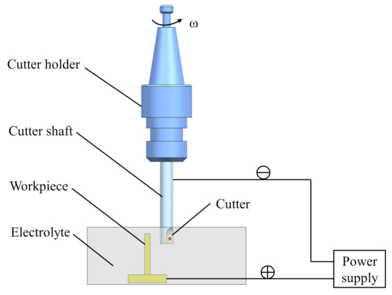
Schematic diagram of electrolytic milling.
Through the combined action of milling and electrochemical machining, the material on the workpiece surface can be removed. Figure 2 shows the schematic diagrams of the material removal thickness for milling, electrochemical machining, and combined electrolytic milling. The milling tool rotates under the action of the spindle, and material is removed from the workpiece surface by the cutter when milling occurs. The material removal thickness and the cutting force caused by material removal are related to the radial cutting thickness of the tool, feed rate and spindle speed, as shown in Fig. 2(a). Figure 2(b) illustrates the material removal process in electrochemical machining. During electrochemical machining, the workpiece and the tool electrode are connected to the positive and negative terminals of the power supply. The material on the workpiece surface is removed through an electrochemical reaction in the electrolyte. In combined electrochemical milling, the machining and electrochemical reactions work simultaneously. Then, the thickness of the removed material via the electrolytic milling method is the same as that via the milling method, while the radial cutting depth of the cutter decreases. The cutting force in electrolytic milling is also less than that in the milling method. The reason is that electrochemical machining removes material from the workpiece surface, and the material removal thickness of milling decreases, as shown in Fig. 2(c). Additionally, when electrochemical and milling processes are combined, the oxide layer formed on the workpiece surface during electrochemical machining is removed by electrochemical milling. The stability of electrochemical processing can be guaranteed, and the machining efficiency, accuracy, and surface quality can be improved.
Fig. 2.
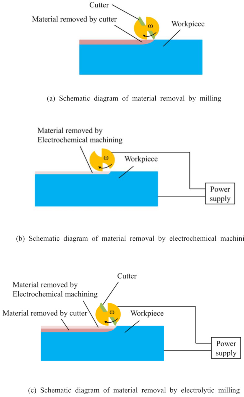
Schematic diagram of material removal by milling, electrochemical machining and electrolytic milling.
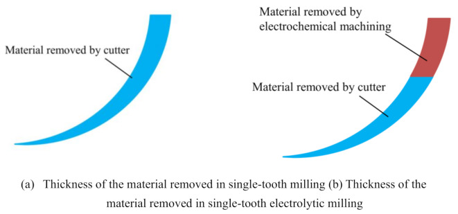
Based on the analysis of the material removal mechanism for milling, the material removal thickness of electrolytic milling in single-tooth machining is shown in Fig. 3(a). The thickness of the material removed by a single tooth of the cutting tool continuously changes under the combined effects of tool rotation and the linear feed when milling machining occurs. The thickness of the removed material is divided into two parts during electrolytic milling. Therefore, the thickness of the removed material includes two parts: the thickness of the removed material in electrochemical machining and the thickness of the removed material in milling, as shown in Fig. 3(b). An analysis of the figure shows that in the material removed by a single tooth, the area with a greater thickness is removed by electrochemical machining, significantly reducing the amount of material removed via the milling process by a single tooth.
Fig. 3.
Thickness of the material removed by a single tooth during milling and electrolytic milling.
Analysis of parameters affecting machining accuracy in electrolytic milling
The main reason for the accuracy errors during the machining of thin-walled parts is workpiece deformation and tool wear. The main cause of workpiece deformation is the excitation of cutting forces on thin-walled workpieces during the cutting process. Therefore, reducing the milling forces during the machining process is one way to reduce workpiece deformation. The factors that affect the machining accuracy of milling are mainly related to the generation of milling forces; these factors include the spindle speed, feed rate, axial cutting depth, and radial cutting depth. In milling processes, the chip thickness changes over time, and the change in the cutting thickness can be represented as follows:
| 1 |
where
| 2 |
where
In the electrolytic milling process, the change in material removal thickness over the part surface is transformed from
| 3 |
The tangential, radial, and axial milling forces can also be converted into milling forces in the X, Y, and Z directions as:
| 4 |
According to the material removal principle of electrochemical milling, the magnitude of the cutting force in the milling process and the machining deformation caused by the cutting force are strongly related to the material removal thickness in the milling process. The machining parameters that affect the accuracy of electrochemical milling include both milling parameters and electrochemical machining parameters, as shown in Fig. 4. The electrochemical machining parameters include the machining voltage, pulse interval, electrolyte concentration and electrolytic gap. The milling parameters include the spindle speed, feed rate and radial cutting depth.
Fig. 4.
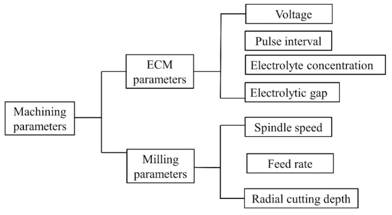
Machining parameters that affect machining accuracy.
Under the action of an applied voltage, an electrochemical field is generated between the anode and cathode. The anode material is removed under the action of an electrochemical reaction, and the volume of removed material can be calculated with the following formula21:
| 5 |
where V is the volume of the electrochemical machining material,
The thickness of the thin-walled part after electrolytic milling is equal to the difference between the thickness of the thin-walled part before machining and the thickness of the removed material. Then, the thickness of the thin-walled part after machining can be expressed as follows:
| 6 |
where
Analysis of workpiece deformation under milling forces
The thin-walled edges of the aluminium alloy box-shaped part were machined by the cutter. The machined edge can be simplified as a rectangular plate with three fixed sides and one free side. When the rectangular edge is subjected to cutting forces, it undergoes elastic deformation. According to the theory of elastic deformation, the three fixed edges satisfy the following boundary conditions:
| 7 |
When the part meets the boundary conditions, the machining deformation caused by different machining positions will vary with the change in position coordinates. Then, the deformation of the thin-walled plate can be expressed as follows:
| 8 |
where
The average material removal thickness in the machining process can also be expressed as follows:
| 9 |
When a thin-walled part is subjected to a cutting force in the Y direction, the thickness of the material removed due to the cutting force in the Y direction can be expressed as:
| 10 |
where
Then, a model for predicting the thickness of thin-walled parts using machining parameters was established. The average material removal thickness is related to the machining parameters. The model for the average material removal thickness is also established as follows:
| 11 |
where
In the electrolytic milling process, because electrochemical machining is a noncontact machining method without cutting forces, the deformation in a thin-walled part is decreased. According to the principles of the dynamic analysis of thin-walled parts, the periodic variation in the milling force during machining leads to dynamic deformation of the workpiece22.
According to formula (2) and formula (3), a reduction in the material removal thickness will decrease the cutting force during the cutting process. While the quality, stiffness, and damping of the workpiece remain unchanged, the variation in cutting force will directly impact the deformation, speed, and acceleration during the machining process. The variation in the material removal thickness during the machining process will have a direct impact on the machining deformation and accuracy of the thin-walled parts, as shown in Fig. 5.
Fig. 5.
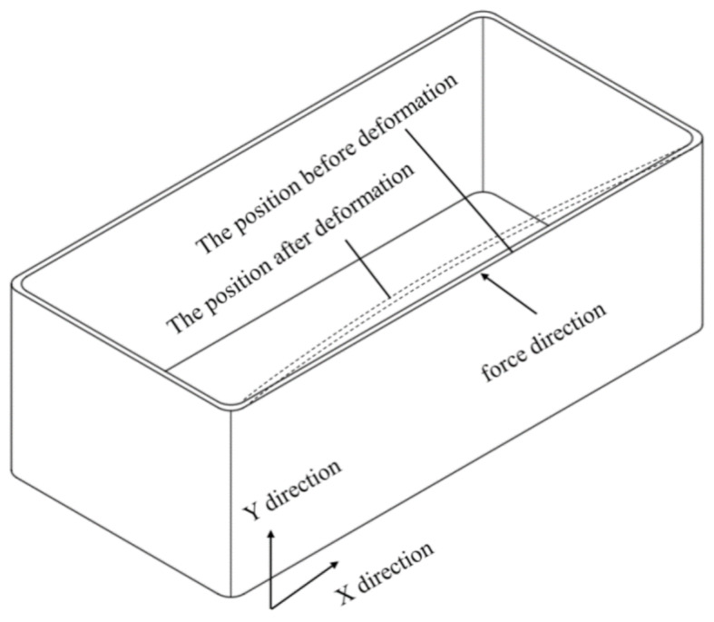
Deformation of a thin-walled part under milling forces.
Experimental settings for electrolytic milling machining
To investigate the influence of the electrolytic milling machining parameters on the accuracy of thin-walled parts, thin-walled 6061 aluminium alloy box parts with a wall thickness of 2.2 mm were chosen as the machining objects, and the dimensions of the parts were 200 mm × 90 mm × 60 mm. Milling experiments, electrolytic milling experiments and electrolytic machining experiments were developed separately. Then, the influence of the machining parameters and machining method on the accuracy can be studied by comparing the accuracy of the machined parts. The thin-walled part in the experiments is shown in Fig. 6.
Fig. 6.
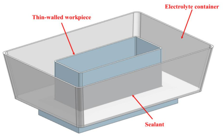
The workpiece for the experiment.
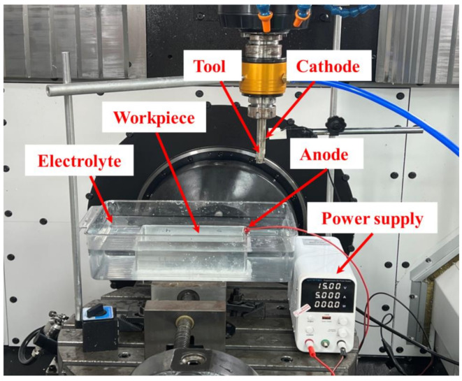
The upper part of the workpiece to be machined is a thin-walled box-shape part and a clamping section is designed as the bottom case. Then, the bottom case can be clamped by the fixture to ensure the rigidity of the clamping during machining. A sealant is applied to the contact surface of the workpiece and the electrolyte container to ensure that the electrolyte does not leak from the electrolyte container. This experiment was conducted on a + GF + Mikron Mill E 500 U five-axis machining centre. The diameter of the milling cutter shaft for electrolytic milling was 16 mm, and the diameter of the milling cutter was 17 mm. In the electrochemical milling process, the cutter shaft also serves as the cathode, while the thin-walled aluminium alloy part acts as the anode. Under the action of an applied voltage, the thin-walled part undergoes electrochemical machining, and the material is removed from the surface of the part via the combined action of milling and electrochemical machining. The experimental setup is shown in Fig. 7. An external voltage, up to a maximum of 30 V from a DC power supply, was applied to the surfaces of the workpiece and the cutter shaft to create a stable electric field. During the electrochemical machining process, the cutter shaft and the part are connected to the negative and positive terminals of the power supply, respectively. If the cutters are also conductors, short circuits can occur as the tool rotates during machining. Then, there is no electrolyte gap between the positive and negative electrodes. Therefore, considering the above two factors, the ceramic (an insulator) inserts is chose. Ceramic cutters were used as machining tools and the diameter of the ceramic cutters is greater than the diameter of the cutter shaft. Then, the electrochemical gap between the cutter shaft and the workpiece can be ensured.
Fig. 7.
Experimental setup for electrolytic milling machining.
Because ceramic cutters are insulating, no electrochemical reaction occurs between the cutter and the workpiece. The electrolyte was a proportionally prepared solution of NaCl. During the machining process, the electrolyte flows through the electrolyte channel in the cutter shaft and impacts the surface of the workpiece.
On the basis of the electrolytic milling experiments, the thickness of the material removed and the dimensional accuracy of the thin-walled parts can be measured on a Hexagon coordinate measuring machine (CMM).
To investigate the effect of the electrolytic milling parameters on the machining accuracy of thin-walled 6061 aluminium alloy parts, milling, electrochemical machining, and electrolytic milling experiments were conducted. All milling operations are carried out by the up-milling method. According to the characteristics of electrochemical machining and materials, suitable electrochemical voltages were determined based on the workpiece material and machining requirements. The applied voltage was set in the range of 0–20 V in this experiment. Since the electrolyte concentration also significantly affects the machining accuracy and speed of electrochemical machining, solutions of NaCl with concentrations of 5%, 10%, 15%, and 20% were designated as electrolytes. The impact of electrolyte concentration on machining accuracy can be considered by electrochemical and electrochemical milling experiments when the concentrations are different. The radial cutting depths were set to 0.25 mm, 0.5 mm, 0.75 mm, and 1 mm and the axial cutting depth during machining was set to 5 mm.
Based on the reference milling experimental parameters, machining parameters such as the spindle speed, feed rate, axial cutting depth, and radial cutting depth were set. Different experimental parameters were used for electrolytic milling and milling to machine the thin-walled parts and to measure the dimensional accuracy and surface roughness of the machined workpieces. The impact of these factors on dimensional accuracy can be studied. The electrochemical machining experimental parameters and milling machining experimental parameters selected for electrochemical milling are shown in Table 1.
Table 1.
Electrolytic milling machining parameters.
| Variables | Spindle speed (Rev/min) | Feed rate (mm/min) | Electrolyte concentration (%) | External voltage (V) | Radial cutting depth (mm) |
|---|---|---|---|---|---|
| 1 | 125 | 50 | 5 | 5 | 0.25 |
| 2 | 250 | 100 | 10 | 10 | 0.5 |
| 3 | 375 | 150 | 15 | 15 | 0.75 |
| 4 | 500 | 200 | 20 | 20 | 1 |
Influence of electrolytic milling parameters on accuracy
According to the electrolytic milling machining parameters shown in Table 1, orthogonal experiments were designed, and electrolytic milling machining experiments were carried out. The thicknesses of the thin-walled parts were measured, and the results are shown in Table 2.
Table 2.
Experimental results of electrolytic milling.
| Variables | Spindle speed (Rev/min) | Feed rate (mm/min) | Electrolyte concentration (%) | External voltage (V) | Radial cutting depth (mm) | Wall thickness after machining(mm) |
|---|---|---|---|---|---|---|
| 1 | 125 | 50 | 5 | 5 | 0.25 | 2.19 |
| 2 | 250 | 100 | 10 | 10 | 0.5 | 2.04 |
| 3 | 375 | 150 | 15 | 15 | 0.75 | 2.08 |
| 4 | 500 | 200 | 20 | 20 | 1 | 1.74 |
| 5 | 125 | 100 | 15 | 20 | 0.25 | 2.16 |
| 6 | 250 | 150 | 20 | 5 | 0.5 | 2.08 |
| 7 | 375 | 200 | 5 | 10 | 0.75 | 2.15 |
| 8 | 500 | 50 | 10 | 15 | 1 | 2.01 |
| 9 | 125 | 150 | 10 | 20 | 0.75 | 2.11 |
| 10 | 250 | 200 | 5 | 15 | 1 | 2.16 |
| 11 | 375 | 50 | 20 | 10 | 0.25 | 1.80 |
| 12 | 500 | 100 | 15 | 5 | 0.5 | 1.81 |
| 13 | 125 | 200 | 10 | 15 | 1 | 2.16 |
| 14 | 250 | 50 | 15 | 20 | 0.25 | 2.13 |
| 15 | 375 | 100 | 20 | 5 | 0.5 | 1.92 |
| 16 | 500 | 150 | 5 | 10 | 0.75 | 2.14 |
According to the theoretical analysis, the material removal thickness is related to multiple machining parameters.
After obtaining the constant coefficients of the material removal thickness prediction formula for the electrolytic milling of thin-walled parts through fitting, the wall thickness after machining
| 12 |
Influence of milling parameters on machining accuracy
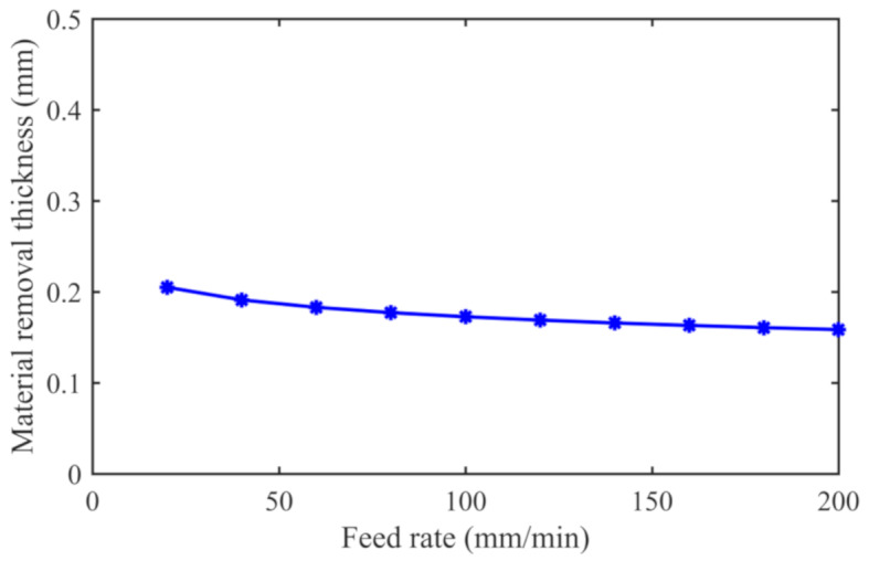
Based on the precision prediction model for electrolytic milling, it is evident that both milling machining parameters and electrochemical machining parameters impact the precision of the electrolytic milling hybrid machining process for thin-walled parts. Therefore, an analysis of the impact of parameters related to electrolytic milling and milling processes on machining precision is conducted. When the feed rate varies within the range of 0–200 mm/min during the milling process while keeping the other parameters constant, an analysis of the impact of the feed rate on machining precision is carried out, as shown in Fig. 8.
Fig. 8.
Effect of the feed rate on dimensional accuracy.
The material removal thicknesses were predicted at intervals of 20 mm/min for comparative analysis when the feed rate was in the range of 0–200 mm/min, as shown in Fig. 8. As the feed rate gradually increases, the material removal thickness decreases from 0.205 mm to 0.156 mm with increasing feed rate. From the analysis of the data in the figure, it can be seen that the change in material removal thickness is not significant with increasing feed rate. The cutting force is generated with increasing feed rate. Then, the elastic deformation of the thin-walled parts occurred, leading to a decrease in the material removal thickness. At the same time, the thickness of the material removed by electrochemical machining decreases after the feed rate increases. Therefore, the decrease in material removal thickness caused by the increase in feed rate is the result of the combined effect of deformation caused by the cutting force and the decrease in material removal thickness by electrochemical machining.
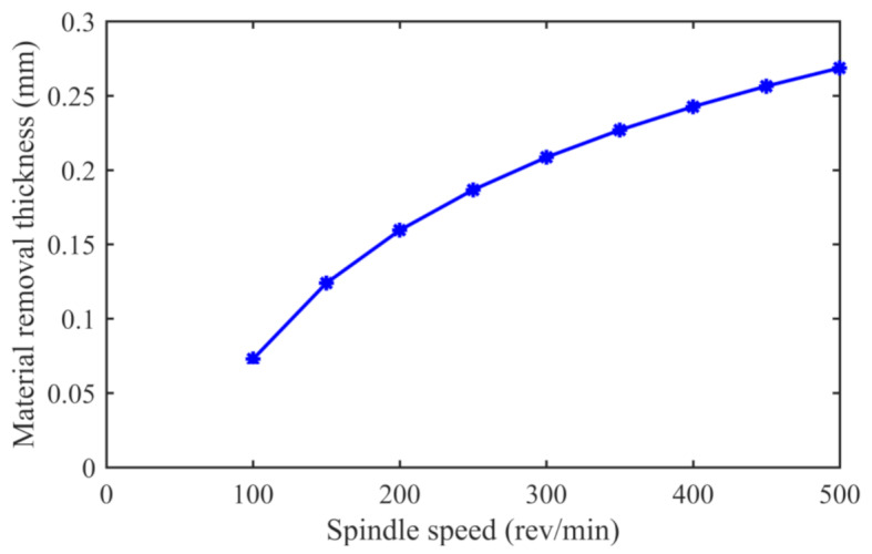
During the electrolytic milling machining process, a milling tool is used to cut and remove the material, while the tool holder acts as the cathode, and the workpiece surface acts as the anode. Then, electrolytic reactions will occur between the two electrodes. When the feed rate is constant, the spindle drives the tool and tool holder to rotate, and the variation in spindle speed affects the per-tooth feed rate of the cutting process, thereby influencing the magnitude of the cutting force generated during the cutting process. During the electrochemical machining process, the ceramic tools are nonconductive. The gaps on the tool holder convert the applied direct current power into pulsed power. Figure 9 illustrates the effect of the variation in the spindle speed on the material removal thickness during the electrolytic milling process. As the spindle speed increases within the range of 100–500 rev/min, there is a noticeable increase in the material removal thickness from 0.073 mm to 0.26 mm, approximately three times the original thickness. This is primarily due to the decrease in the per-tooth feed rate leading to a reduction in the cutting force, thus reducing the deformation of thin-walled workpieces during the cutting process. Then, the material removal thickness of each tooth decreases, so the cutting force decreases with increasing spindle speed, and the cutting deformation generated by the thin-walled parts decreases. Then, the material removal thickness is close to the theoretical value.
Fig. 9.
Effect of the spindle speed on the dimensional accuracy.
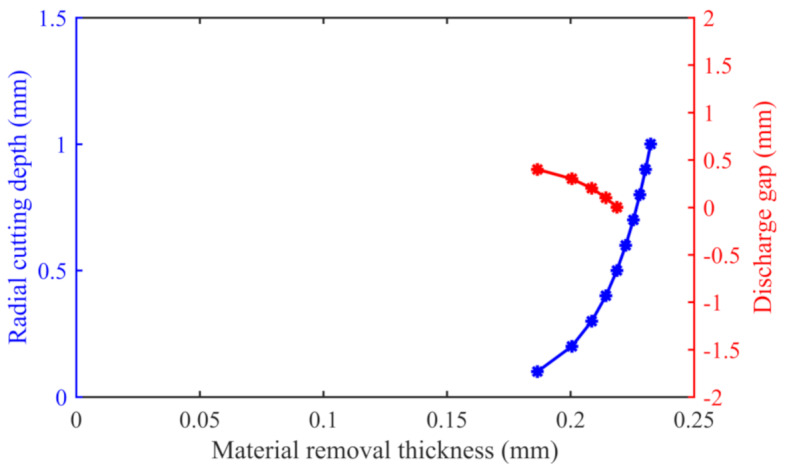
In the electrolytic milling process, the variation in radial cutting depth affects the magnitude of the cutting force and influences the electrochemical gap between the tool holder and the workpiece. On the basis of the precision prediction model for electrochemical milling hybrid machining, the effect of radial cutting depth variation on the material removal thickness was determined, as shown in Fig. 10. Analysis of the graph reveals that as the radial cutting depth increases within the range of 0–1 mm, the material removal thickness gradually increases within the range of 0.2–0.25 mm. The material removal thickness nonlinearly increases from 0.2 mm to 0.25 mm. When the electrochemical discharge gap decreases from 0.5 mm to -0 mm, there is a clear upward trend in the material removal thickness from 0.18 mm to 0.22 mm. Therefore, with increasing radial cutting depth and decreasing electrochemical discharge gap, the material removal thickness significantly increases. However, the cutting thickness still does not reach its theoretical value due to the influence of machining deformation. It can be concluded that the electrochemical discharge gap gradually increases with increasing radial cutting depth during the electrolytic milling process. An increase in the radial cutting depth will lead to an increase in the removal thickness of the milling material, while an increase in the electrolytic gap will lead to a decrease in the removal thickness during electrochemical machining.
Fig. 10.
Effect of the radial cutting depth on the dimensional accuracy.
Influence of electrolytic parameters on machining accuracy
In the machining accuracy prediction model of electrolytic milling, electrochemical machining parameters also have an impact on the machining accuracy of the workpiece. Therefore, the influence of electrochemical machining parameters on machining accuracy is studied by changing parameters such as voltage, voltage discharge period, and electrolyte concentration.
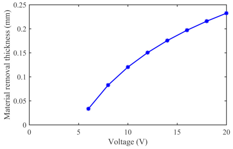
When the electrochemical machining voltage is increased within the range of 6–20 V, there is a significant increase in the removal thickness of the material. For instance, the material removal thickness increases from 0.03 mm at 6 V to 0.23 mm at 20 V, as shown in Fig. 11. Comparative analysis reveals that as the electrochemical voltage increases, the electrochemical machining power also increases. As the voltage increases, there is a significant increase in the material removal thickness. The main reason for the increase in the material removal thickness due to the increase in the voltage parameter under constant resistance is that the increase in the voltage parameter causes an increase in the current. This results in an increase in the material removal thickness during electrochemical machining. At the same time, an increase in the removal thickness during electrochemical machining reduces the removal thickness during the milling process. Then, the milling force and the deformation of the thin-walled part also decreases.
Fig. 11.
Effect of voltage on the dimensional accuracy.
As the spindle speed increases, the discharge period of the pulse power supply decreases accordingly. Therefore, the decrease in the pulse discharge period caused by the change in spindle speed significantly reduces the material removal thickness, as shown in Fig. 12. When the pulse discharge period is reduced from 0.6 s to 0.06 s, the material removal thickness increasesfrom 0 mm to 0.269 mm. The material removal thickness decreases as the voltage discharge period decreases. According to formula (12), the material removal thickness in the electrolytic milling process is an exponential function related to the electrolytic machining voltage. When the discharge period is reduced, the energy provided by the power supply is reduced in the process of electrolytic machining, resulting in a significant reduction in the material removal thickness in the electrolytic machining process.
Fig. 12.
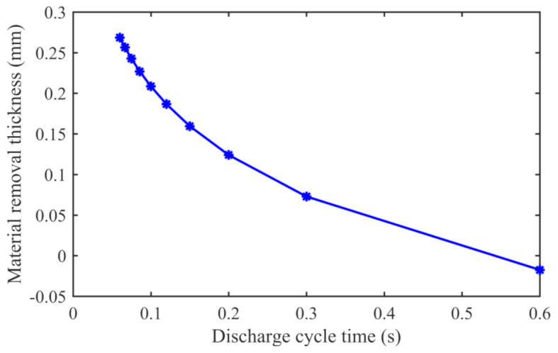
Effect of the discharge cycle time on dimensional accuracy.
To study the effect of electrolyte concentration on material removal, the concentration of NaCl electrolyte in the model was adjusted. The electrolyte concentration in electrochemical machining is set at an interval of 3%, in the range of 3–30%, and the material removal thickness predicted by the model is analysed. As the electrolyte concentration increased from 3 to 30%, the material removal thickness decreased from 0.22 mm to 0.18 mm, as shown in Fig. 13. During the electrochemical machining process, a higher concentration of electrolyte leads to a greater material removal rate. In electrolytic milling, the reason for the reduction in material removal rate may be due to the increase in concentration, which removes a small amount of material, resulting in decreased rigidity of the workpiece. This increase in deformation of the workpiece during milling leads to a slight reduction in the amount of material removed. Consequently, this results in a minor decrease in the material removal thickness in electrolytic milling. Through comparative analysis, compared with other electrochemical machining process parameters and milling process parameters, the electrolyte concentration has little effect on the material removal thickness of electrochemical machining. A change in the electrolyte concentration did not have an insignificant impact on the removal of the material during electrochemical milling hybridmachining.
Fig. 13.
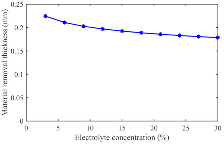
Effect of the electrolyte concentration on the dimensional accuracy.
Discussion
To investigate the influence of electrolytic milling on the material processing accuracy, thin-walled aluminium alloy parts were selected for machining. The machining experiments were conducted using three different methods: electrochemical machining, milling, and electrochemical milling hybrid machining. Due to the differences in the rigidity of different areas of the workpiece, the machining accuracy varies in each region. A coordinate measuring machine was used to measure the material removal thickness within the 0–80 mm range along the length of the workpiece, and the results are shown in Fig. 14.
Fig. 14.
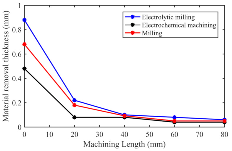
Effect of the machining method on the dimensional accuracy.
An analysis of the figure reveals that the workpiece exhibits better rigidity and less elastic deformation at a machining length of 0 mm. As machining continues, the rigidity of the workpiece weakens. Moreover, the material removal thickness at 0 mm is greater than that in the other regions. When the machining distance from the initial position reaches 80 mm, the material removal thickness is at its minimum. Among the three machining methods, the material removal thicknesses at the initial position for electrolytic milling, milling, and electrochemical machining were 0.88 mm, 0.68 mm and 0.48 mm, respectively. Electrolytic milling combines the material removal methods of milling and electrochemical machining, resulting in the largest material removal thickness. It is 0.2 mm higher than milling and the increased value is about 29.4% of the removed thickness of the milled material. When the machining distance reaches 80 mm from the initial position, the material removal thickness for electrolytic milling machining is 0.06 mm. The material removal thicknesses for milling and electrochemical machining are approximately 0.05 mm and 0.04 mm, respectively. The material removal thickness of electrolytic milling hybrid machining is 0.01 mm higher than that of milling, which is about 20% of the material removal thickness of milling. As the machining continues along the machining direction, the deformation of the thin-walled workpiece leads to a decrease in the material removal thickness. However, throughout the entire machining process, the material removal thickness of the electrolytic milling method is significantly greater than that of electrochemical machining and milling.
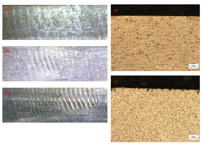
The surfaces of the workpieces processed by the above three machining methods were obtained through a three-dimensional video microscope, as shown in Fig. 15. Figure 15(a) shows the surface after electrolytic milling, Fig. 15(b) shows the surface after electrochemical machining, and Fig. 15(c) shows the surface after milling machining. The results indicate that the surfaces of Fig. 15 (a) and (b) are similar. The workpiece surface in Fig. 15(a) not only has traces of electrochemical machining but also has traces of material removal by milling tools. The surface quality of Fig. 15(c) is poor, and obvious machining marks are visible on the surface that have not been removed. The comparison in the figure reveals that the surface of the thin-walled aluminium alloy box parts has distinct vibration marks during the milling process because of the effect of the milling force on the thin-walled edge. Electrochemical machining has no milling force on the workpiece, so there is no obvious trace on the surface of the workpiece. Electrolytic milling combines the benefits of both methods, leading to enhanced processing efficiency and improved surface quality of the workpiece. The metallographic structure diagrams of the workpiece after milling and electrolytic milling were illustrated in Fig. 15(d) and (e). Figure 15 (d) shows typical characteristics of rolled microstructure, primarily consisting of large lamellar structures. The grain structure is layered, with some strengthening phases present between the grain structures. Figure 15 (e) indicates a significant refinement of the original microstructure. The grains and the reinforcing phases between the grain structures are more refined. According to the principles of electrolytic milling, the grain refinement observed in Fig. 15 (e) may be attributed to the rise in temperature in the electrolytic machining process followed by a rapid decrease.
Fig. 15.
Surface of the part machined by different machining methods: (a) electrolytic milling surface, (b) electrochemical machining surface (c) milling surface (d) Metallographic structure diagram of the workpiece after milling (e) Metallographic structure diagram of the workpiece after electrolytic milling.
To verify the reliability of the prediction model for electrolytic milling, two sets of experiments were conducted. The box aluminium thin-wall parts with a length of 80 mm, a height of 60 mm and a wall thickness of 2.2 mm were machined by the electrolytic milling method, and the material removal thickness of the workpiece was measured at intervals of 20 mm over a length range of 0–80 mm. The experimental measurement results were then compared with the model’s predicted results at 40 mm, as shown in Fig. 16. The first machining parameters of electric milling are a spindle speed of 200 rev/min, a feed rate of 100 mm/min, a voltage of 15 V, an electrolyte concentration of 15% and a radial cutting depth of 1 mm. The predicted material removal thickness at 40 mm from the initial position is 0.17 mm, and the measured value is 0.2 mm. The second machining parameters of electric milling include a spindle speed of 100 rev/min, a feed rate of 50 mm/min, a voltage of 20 V, an electrolyte concentration of 15%, and a radial cutting depth of 0.5 mm. The predicted material removal thickness at 40 mm from the initial position is 0.26 mm, and the measured value is 0.24 mm. The errors between the prediction results and measurement results are 0.03 mm and 0.02 mm, respectively. The errors between the material removal thickness prediction model and the measured results are 15% and 8%, respectively, and the accuracy of the prediction model is verified.
Fig. 16.
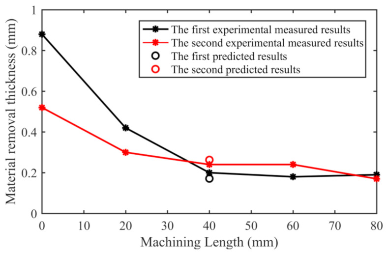
Experimental validation of the accuracy of the predicted dimensionality in electrolytic milling.
Conclusions
This paper proposes an electrolytic milling method to enhance the machining accuracy of thin-walled parts. The removal mechanism of the material during electrolytic milling was analysed. Based on the results of the electrolytic milling machining experiment, a precision prediction model was proposed for electrolytic milling. The experimental results of part machining accuracy were collected. By varying the electrolytic milling parameters, the effects of these parameters on the machining accuracy were studied. The main conclusions are summarized as follows:
The factors that influence the machining accuracy of thin-walled parts in electrolytic milling are analysed. During the milling process of thin-walled parts, deformation is prone to occur, and the machining accuracy can be affected. Machining parameters such as the spindle speed, feed rate, electrolyte concentration and machining voltage all affect the machining accuracy of the parts.
An experimental plan for electrolytic milling is designed, and experiments are implemented. Based on the experimental measurements, a precision prediction model for the machining accuracy of thin-walled parts in electrolytic milling is established. Model validation experiments are conducted to confirm the reliability of the model. Two sets of validation experiments were conducted and the errors between predicted results and the measured results are 15% and 8%, respectively.
Based on the precision prediction model for the hybrid machining accuracy of thin-walled parts, an analysis of the impact of machining parameters such as the spindle speed, feed rate, electrolyte concentration, and machining voltage on machining accuracy is carried out. The spindle speed and voltage pulse frequency have the most significant impacts on machining accuracy. Within the range of 0-500 rev/min for the spindle speed, as the spindle speed increases, the material removal thickness increases from 0.073 mm to 0.26 mm, approximately three times the original thickness.
The machining accuracies of thin-walled parts using three different machining methods, i.e., electrochemical machining, milling, and electrolytic milling, are compared. The material removal thickness of the electrolytic milling method is significantly greater than that of the electrochemical machining and milling methods. Through the comparative analysis of the two measured material removal thickness, electrolytic milling hybrid machining increased by 20% and 29.4% compared with milling machining, respectively.
Acknowledgements
This work was partially supported by the Key University Science Research Project of Jiangsu Province of China (18KJA460004, 21KJA460011, 22KJA460006) and the Research Fund of the Nanjing Institute of Technology (ZKJ202103).
Author contributions
Author Junming Hou designed the model, analyzed the computational results, and contributed to the interpretation of these results for the manuscript. Author Baosheng Wang supervised the project, provided strategic direction in algorithm development and testing, and conducted a thorough review and final approval of the manuscript prior to submission. Author Dongsheng Lv designed and executed the performance tests. Author Changhong Xu provided critically revised the manuscript for important content.
Data availability
Data AvailabilityThe data that support the findings of this study are available from the corresponding author.
Declarations
Competing interests
The authors declare no competing interests.
Footnotes
Publisher’s note
Springer Nature remains neutral with regard to jurisdictional claims in published maps and institutional affiliations.
References
- 1.Wan, M. et al. Chatter suppression in the milling process of the weakly-rigid workpiece through a moving fixture [J]. J. Mater. Process. Technol.299, 117293 (2022). [Google Scholar]
- 2.Hou, J. et al. Machining stability enhancement in multi-axis milling of titanium hollow blade by introducing multiple damping and rigid supporters [J]. J. Manuf. Process.64, 198–208 (2021). [Google Scholar]
- 3.Dang, X. B. et al. Chatter analysis and mitigation of milling of the pocket-shaped thin-walled workpieces with viscous fluid [J]. Int. J. Mech. Sci.194, 106214 (2021). [Google Scholar]
- 4.Wang, H. et al. Integrated analysis method of thin-walled turbine blade precise machining [J]. Int. J. Precis. Eng. Manuf.16 (5), 1011–1019 (2015). [Google Scholar]
- 5.Butt, M. A. et al. Five-axis milling vibration attenuation of freeform thin-walled part by eddy current damping [J]. Precis. Eng.51, 682–690 (2018). [Google Scholar]
- 6.Uddin, M. S. et al. A Tool path Modification Approach to cutting Engagement Regulation for the improvement of Machining Accuracy in 2D milling with a straight End Mill [J]. J. Manuf. Sci. Eng.129 (6), 1069–1076 (2007). [Google Scholar]
- 7.Wang, J., Ibaraki, S. & Matsubara, A. A cutting sequence optimization algorithm to reduce the workpiece deformation in thin-wall machining [J]. Precis. Eng.50, 506–514 (2017). [Google Scholar]
- 8.Chu, C. H., Huang, W. N. & Hsu, Y. Y. Machining accuracy improvement in five-axis flank milling of ruled surfaces [J]. Int. J. Mach. Tools Manuf.48 (7–8), 914–921 (2008). [Google Scholar]
- 9.Hao, X. et al. A time-varying geometry modeling method for parts with deformation during machining process [J]. J. Manuf. Syst.55, 15–29 (2020). [Google Scholar]
- 10.Ding, G. et al. Prediction of machining accuracy based on a geometric error model in five-axis peripheral milling process [J]. Proceedings of the Institution of Mechanical Engineers Part B Journal of Engineering Manufacture. 228(10), 1226–1236 (2014).
- 11.Zong, Y., Liu, J. & Zhu, D. Improving blade accuracy via local electrochemical machining with partial insulated cathodes [J]. Precis. Eng.76, 284–293 (2022). [Google Scholar]
- 12.Sharma, V. et al. Investigations into machining accuracy and quality in wire electrochemical micromachining under sinusoidal and triangular voltage pulse condition [J]. J. Manuf. Process.62, 348–367 (2021). [Google Scholar]
- 13.Zhang, J. et al. Improvement of trailing edge accuracy in blisk electrochemical machining by optimizing the electric field with an extended cathode [J]. J. Mater. Process. Technol.231, 301–311 (2016). [Google Scholar]
- 14.Wang, H., Zhu, D. & Liu, J. Improving the accuracy of the blade leading/trailing edges by electrochemical machining with tangential feeding [J]. CIRP Ann. Manuf. Technol.68 (1), 1–4 (2019). [Google Scholar]
- 15.Wang, F. et al. Experimental research on improving accuracy of electrochemical machining of deep narrow grooves [J]. Int. J. Adv. Manuf. Technol.96, 3217–3225 (2018). [Google Scholar]
- 16.Wang, J., Xu, Z. & Zhu, D. Improving profile accuracy and surface quality of blisk by electrochemical machining with a micro inter-electrode gap [J]. Chin. J. Aeronaut.36 (4), 523–537 (2023). [Google Scholar]
- 17.Wang, M. & Qu, N. Investigation on material removal mechanism in mechano-electrochemical milling of TC4 titanium alloy [J]. J. Mater. Process. Technol.295 (1), 117206 (2021). [Google Scholar]
- 18.Mishra, K. et al. Experimental investigation into electrochemical milling of Ti6Al4V [J]. J. Manuf. Process.29, 113–123 (2017). [Google Scholar]
- 19.Li, H. et al. Simulation and Experimental Investigation of Electrochemical Mill-grinding of GH4169 alloy [J]. Int. J. Electrochem. Sci.13, 6608–6625 (2018). [Google Scholar]
- 20.Yue, X. et al. Improving the machined bottom surface in electrochemical mill-grinding by adjusting the electrolyte flow field [J]. J. Mater. Process. Technol.276, 116413 (2020). [Google Scholar]
- 21.Wang, X., Li, H. & Niu, S. Simulation and experimental research into combined electrochemical milling and electrochemical grinding machining of Ti40 titanium alloy [J]. Int. J. Electrochem. Sci.15, 11150–11167 (2020). [Google Scholar]
- 22.Altintas, Y. Manufacturing Automation: Metal Cutting Mechanics, Machine tool Vibrations, and CNC Design [M] (Cambridge University Press, 2000).
Associated Data
This section collects any data citations, data availability statements, or supplementary materials included in this article.
Data Availability Statement
Data AvailabilityThe data that support the findings of this study are available from the corresponding author.


