Abstract
We have designed and synthesized a molecular rod that consists of two weakly coupled electronic π -systems with mutually shifted energy levels. The asymmetry thus implied manifests itself in a current–voltage characteristic with pronounced dependence on the sign of the bias voltage, which makes the molecule a prototype for a molecular diode. The individual molecules were immobilized by sulfur–gold bonds between both electrodes of a mechanically controlled break junction, and their electronic transport properties have been investigated. The results indeed show diode-like current–voltage characteristics. In contrast to that, control experiments with symmetric molecular rods consisting of two identical π -systems did not show significant asymmetries in the transport properties. To investigate the underlying transport mechanism, phenomenological arguments are combined with calculations based on density functional theory. The theoretical analysis suggests that the bias dependence of the polarizability of the molecule feeds back into the current leading to an asymmetric shape of the current–voltage characteristics, similar to the phenomena in a semiconductor diode.
Keywords: molecular electronics, rectification, single-molecule studies
The idea to build an electronic device based on single molecules is today called Molecular Electronics (1–4). Conceptually and historically, this field starts out from electron transfer physics (5) and chemistry (6, 7), where a single electron is transferred within a molecule. Often, the transfer from an electron-rich conjugated system (donor = D) to a second unit (acceptor = A) via non conjugated σ-bonds serves as model system (8, 9). In this spirit, Aviram and Ratner proposed in 1974 (10) a Gedankenexperiment to realize a diode with a D–σ–A molecule connected at either end to metallic leads. The new aspect of this idea was that the combined system of electrons plus leads could support a continuous sequence of electron transfer processes, i.e., a stationary current. For the particular setup considered, the current–voltage characteristic (I–V) was predicted to be rectifier-like.
In the case of transport experiments, the concept of D and A parts of a molecule is less meaningful than it is for isolated molecules, because the original role of donating and accepting charges is taken over by the reservoirs. However, in the presence of electrodes the D–A structure implies a broken symmetry. The consequences for transport thereof can depend on the detailed level structure and for a given molecule are not easily predicted (11). In principle, however, the D–A system shares similarities with a semiconductor diode, and we suggest that this picture also applies to our experiment.
Experimentally, D–σ–A molecule devices have been built by using Langmuir–Blodgett films in-between two planar electrodes (12). Recently, block copolymers with a D–σ–A structure displayed rectifier properties as self-assembled monolayer in scanning probe experiments (13). Asymmetric I–Vs may further be generated by employing different molecule–electrode contacts on the two ends (14, 15), by asymmetrically placing a resonant level in between the electrodes (16–18), or simply by using different metals (19). Experimentally, asymmetric I–Vs may also occur as a consequence of metallic defects in the molecular film.
Besides experiments with molecular film devices, tailor-made molecular rods can alternatively be contacted individually by employing the mechanically controlled break junction (MCB) technique (20–22), a method that has successfully been applied for systematic comparative studies (14, 23, 24).
In this experiment, we designed and synthesized a series of molecular rods consisting of two separated π -systems and equipped with terminal acetyl protected sulfur anchor groups that are required for MCB experiments. The modular assembly of the molecular structure allowed the synthesis of the desired asymmetric D-A rod and of both symmetric rods (D–D and A–A) for control experiments. The electronic characterization is then performed employing the MCB technique. The measurements are reproduced several times. The data are analyzed both by using simple phenomenological arguments and by comparison with extensive numerical studies.
Design, Synthesis, and Characterization of the Molecules
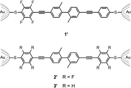
To bridge both electrodes of a MCB with a molecule, a rigid and linear molecular rod with suitable anchor groups is required. The intended electronic asymmetry is based on partitioning the molecular rod in two separated π -segments of comparable structural features but different D–A properties. It is crucial to keep both π -systems as similar as possible in size, building blocks and anchor groups to minimize effects on the electronic transparency other than the electronic energy levels. Both π -systems were linked by a C–C bond. Sterical repulsion induces a substantial torsion angle between the segments and reduces the overlap of their π -orbitals and hence their electronic coupling. Structurally, both π -systems consist of ethynyl-linked benzene cores and are thus very comparable. To vary the electronic properties of one segment, the parent unit was functionalized with four electron-deficient fluorine atoms. The modular synthetic strategy allows one to choose the individual subunits of the molecular rod, such that two units are easily combined either as a D–A system (molecule 1) or as symmetric combinations (molecules 2 and 3). As electronic rectification by the molecules' design was envisaged, 1 is the target structure, whereas 2 and 3 serve for control experiments but were also of special interest to investigate the influence of charging of the molecules in a contact.
More precisely, the designed molecular rods consist of two phenyl–ethynyl–phenyl π -systems, which are fused by a biphenylic C–C bond. The steric repulsion of two methyl groups in ortho position to the biphenylic C–C link induces a torsion angle to separate both π -systems. Terminal acetyl protected sulfur groups allow for immobilization between the gold electrodes of a MCB similar to previous experiments (14, 23, 24). We expect these molecular rods to form covalent Au–S bonds and to occur in the junction in their immobilized forms 1′, 2′, and 3′, respectively (Fig. 1).
Fig. 1.
The rectifying device consisting of a single molecule 1′ immobilized between two Au electrodes and the corresponding control experiments with the immobilized symmetric molecular rods 2′ and 3′ between an Au electrode pair of a MCB.
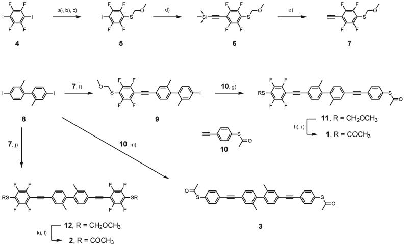
The synthesis of the molecular rods 1, 2, and 3 is shown in Scheme 1. The electron-deficient fluorinated benzene subunit was assembled starting with commercially available 4. Treatment with 2.5 eq of tert.butyllithium at –78°C, subsequent quenching with stoichiometric amounts of elemental sulfur, and protection of the sulfide by addition of bromomethylmethylether gave the methylmethoxy (MOM)-protected 5 as a yellowish oil. Substitution of the iodine with trimethylsilyl (TMS) acetylene gave the TMS-protected, sulfur-functionalized, and fluorinated phenylacetylene 6 after column chromatography (CC). Deprotection of the TMS group by catalytic amounts of K2CO3 in methanol afforded the free acetylene 7 as a white solid almost quantitatively. The modular central π -delocalization dividing subunit 8 was prepared from 3-nitrotoluene by a benzidine rearrangement and a Sandmeyer reaction according to literature procedures (25, 26). To favor the single substituted reaction product, a fivefold excess of the diiodo compound 8 was used in the Sonogashira reaction with the fluorinated acetylene 7 to afford the mono-substituted product 9 as a white solid. Substitution of both iodines gave the fully fluorinated molecular rod 12 asaside product in 10% yield. The iodine of 9 was substituted with 10 (24) to assemble the molecular rod 11, which has been isolated as a white solid by CC.
Scheme 1.
Synthesis of the molecular rods 1-3. a), tert.-BuLi, THF, –78°C; b), S8, room temperature (RT); c), BrCH2OCH3, –78°C, RT, 77%; d), HCCSi(CH3)3, CuI, [Pd(PPh3)2Cl2], Et3N, 40°C, 69%; e), K2CO3,CH3OH, RT, 98%; f), CuI, [Pd(PPh3)2Cl2], Et3N, 40°C, 72%; g), CuI, [Pd2(dba)3]·CHCl3, PPh3, Et(i-Pr)2N, THF, RT, 67%; h), AgNO3, CH2Cl2, EtOH, RT; i), AcCl, Ac2O, CH3C6H5, RT, 37%; j), CuI, [Pd2(dba)3], PPh3, Et3N, 40°C, 93%; k), AgNO3, EtOH, RT; l), AcCl, C5H12, RT, 90%; m), CuI, [Pd2(dba)3], PPh3, Et(i-Pr)2N, THF, RT, 74%.
Compound 11 already comprises the structure of the electronically asymmetric molecular rod bearing terminal sulfur anchor groups. Slow diffusion of pentane into a solution of 11 in dichloromethane gave single crystals suitable for x-ray analysis (Fig. 2). Compound 11 crystallizes in the triclinic space group  .** The length of the molecular rod given by the intramolecular S–S distance is 2.43(4) nm. The large torsion angle between both benzene rings of the central 2,2′-dimethyl-biphenyl unit of 75.00(8)° is minimizing the orbital overlap and thus the electronic coupling of both π -systems. The phenyl rings of both diphenylacetylene π -systems are almost coplanar.
Fig. 2.
Molecular structure of compound 11 having two different protection groups on the terminal sulfur (50% probability thermal ellipsoids). Selected bond lengths (pm) and bond angles (°): S(1)—C(2) 183.1(3), S(1)—C(3) 177.1(3), S(2)—C(30) 178.2(3), S(2)—C(33) 178.6(4), F—C 134.3(3)—135.4(3), O(1)—C(1) 142.6(5), O(1)—C(2) 139.9(4), O(2)—C(33) 118.7(4), C(9)—C(10) 120.0(4), C(14)—C(18) 150.1(3), C(25)—C(26) 120.1(5); C(2)—S(1)—C(3) 102.6(2), C(30)—S(2)—C(33) 103.8(2), C(1)—O(1)—C(2) 112.3(2), C(6)—C(9)—C(10) 179.0(3), C(9)—C(10)—C(11) 175.6(3), C(22)—C(25)—C(26) 178.6(4), C(25)—C(26)—C(27) 176.7(4).
Although two different protection groups are of particular interest, when a defined orientation of the asymmetric molecular rods in an electronic device is desired for self-assembled monolayers (27, 28), acetyl-protected terminal sulfur anchor groups are ideally suited for single-molecule investigations in a MCB.
To cleave the robust MOM group, 11 was treated with silver nitrate in a dichloromethane/ethanol mixture at room temperature (29). The obtained yellowish silver salt was suspended in toluene, and a mixture of acetic anhydride and acetyl chloride was added to afford the target compound 1 as a white solid.
Furthermore, both symmetric molecular rods 2 and 3 have been synthesized for control experiments. Rod 12, which is fluorinated on both sides, has already been obtained as a side product during the synthesis of 9. To improve the yield, 2.4 eq of 7 and the diiodine 8 were exposed to similar coupling conditions to afford 12 as a slightly yellow solid in 93% yield. A similar deprotection–reprotection procedure as applied for 11 afforded 2 in 89% yield. The symmetric rod 3 was obtained from 2.4 eq of the acetylene 10 and the diiodine 8 in 74% yield.
All compounds were characterized by mass spectrometry, 1H- and 13C-NMR spectroscopy, and elemental analysis.
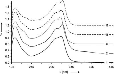
The frontier orbitals [highest occupied molecular orbital (HOMO), lowest unoccupied molecular orbital (LUMO)] are expected to dominate electron transport at low bias. Although the coupling of the molecule to electrodes is assumed to drastically influence the energetic levels of the orbitals, the HOMO–LUMO gap of the molecule in solution is an indicator of the electronic coupling between both π -segments. UV-visible spectra of 1-3, 11, and 12 are displayed in Fig. 3.
Fig. 3.
UV-visible spectra of the molecular rods 1-3, 11, and 12 (1 × 10⁻⁵ M in CH3CN; T = 298 K). For clarity the spectra were shifted horizontally by steps of 0.4 units.
All spectra display an absorption band at ≈204 nm, which in analogy to studies with oligophenylenes (30, 31) can be attributed to the common central biphenyl unit. At a longer wavelength, all five rods display an intense peak with a hypsochromic shoulder shifted by 12–14 nm. These double peaks are probably due to both the individual delocalized diphenylacetylene π -systems and the whole rod-like backbone. The intense peak shifts from 317.5 nm for the unfluorinated symmetric rod 3 to 319.5 nm and 320.0 nm, respectively, for the asymmetric fluorinated rods 1 and 11 and further to the red to 323.0 nm for both symmetrical fluorinated rods 2 and 12. Furthermore, a broad weak shoulder up to 395 nm is observed for the symmetric compound 2 and the asymmetric structure 1. However, this feature is not found for the corresponding compounds with MOM sulfur protection groups and can presumably be assigned to enlarged delocalization due to the acetyl groups on the fluorinated thiophenol. 1-3, 11, and 12 display qualitatively similar UV-visible spectra suggesting comparable spacing between their frontier orbitals and comparable structural features. In particular, the common longest-wavelength absorptions of all five rods indicate a comparable coupling of the two π -subunits.
Conductance Experiments
To contact the molecules electronically from two sides, we have used the mechanically controllable break junction technique. It was already demonstrated in former experiments that single molecules (or, at most, very few) could be contacted by using this technique (14). The experimental protocol is described in detail in refs. 14 and 32. Briefly, we establish an electrode pair by breaking a lithographically fabricated gold wire. The contact may be opened and closed by mechanical means, and atomically sharp gold tips can be shaped. To immobilize individual molecules on the surface of the gold electrodes, they are exposed for a short time from solution. The acetyl protection group slows down the immobilization kinetics (33). This reduces the density of molecules on the surface and prevents aggregation of larger assemblies. Single-molecule contacts are formed by repeatedly opening and closing the junction, while the conductance properties simultaneously were recorded. We obtain stable conditions under which the I–Vs can be recorded repeatedly. In former experiments with different molecules, these stable contacts could be related to single-molecule junctions. We will see that the results discussed below further support the notion that we indeed have single-molecule contacts. Because of the experimental conditions, the electronic properties of the junction may be affected by the uncontrolled presence of other molecules or irregular electrode surfaces nearby, causing sample-to-sample fluctuations in the experimental results.
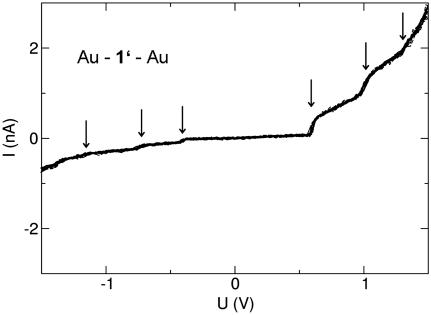
The experiments were performed at T ∼ 30 K with molecules 1, 2, and 3 independently. Fig. 4 shows data for molecule 1′ immobilized between both Au electrodes of a MCB. The current–voltage data repeatedly recorded for Au–1′–Au show some step-like features both at positive voltages and less pronounced at negative voltages (see arrows). The general shape of the I–V is clearly asymmetric, indeed showing a diode-like behavior. A comparison of the current level at U =±1.5 V yields a rectification ratio of 1:4.5.
Fig. 4.
I–V reproducibly recorded for a stable Au–1′–Au junction in a MCB at T ∼ 30 K. Arrows point to step-like features of the I–V.
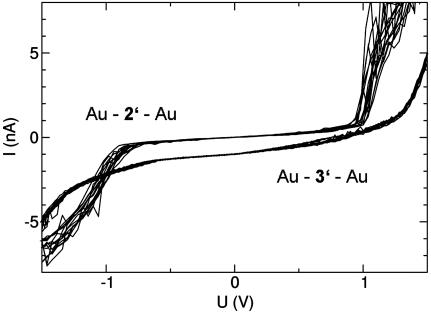
The comparison with data obtained with molecules 2 and 3 is useful to develop a qualitative picture. Fig. 5 shows data obtained with the immobilized molecules 2′ and 3′, respectively. The data set above recorded for Au–2′–Au clearly shows a symmetric shape of the I–Vs with a current blockade up to a threshold of U ∼ 0.8 V and then a strong increase of the current. Similar, but somewhat less pronounced, are the results obtained for Au–3′–Au (lower data set, shifted by –1 nA for clarity), which also show small asymmetries in the shape but nevertheless very similar current levels at V = ±1.5 V. The fact that immobilized symmetric molecules 2′ and 3′ yield symmetric I–Vs, whereas the immobilized asymmetric molecule 1′ gives asymmetric I–Vs allows for three qualitative conclusions: (i) Indeed the sample molecules are contacted, not any unintended and uncontrolled contamination. (ii) The molecules are contacted in a fashion similar to the cartoon in Fig. 1. If, for example, the molecules would be formed by polymer-like chains of the sample molecules or by a larger bulk-like assembly, the I–Vs would not reflect the symmetry properties of the molecule in a systematical way. (iii) Most likely, a single molecule (or at most very few) forms the contact. We infer this from the fact that many molecules in parallel, oriented randomly, would add onto symmetrized I–Vs.
Fig. 5.
I–Vs reproducibly recorded for stable Au–2′–Au and Au–3′–Au junctions in a MCB at T ∼ 30 K.
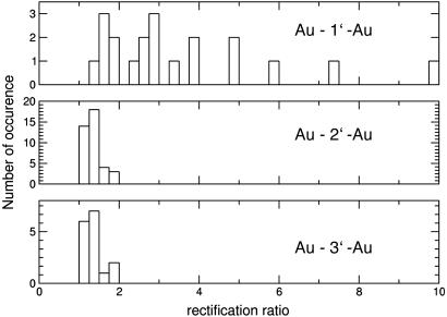
How reliable are these findings? Before discussing the qualitative differences between the curves, a statistical view over all stable contacts (i.e., I–Vs that could be consecutively and repeatedly recorded) gives clear evidence that the symmetric/asymmetric bias dependence is indeed related to the choice of the molecule. The histograms displayed in Fig. 6 plot the occurrence of the ratio of the current values of the positive and negative branch, evaluated at |U| = 1.5 V (one stable and reproducible contact is counted as one event; the larger current is always taken in the numerator of the rectification ratio).†† For the immobilized symmetric molecules 2′ and 3′, values are found close to 1 (in the range of 1–1.8), as expected for a symmetric molecular junction. It should be stressed that not only the symmetry of the molecule is of importance, but also asymmetric chemical bonds to the leads or any other configuration asymmetries may cause I–V asymmetries. In contrast to that, contacts with immobilized molecule 1′ always show values different from unity, ranging from 1.4 to 10. There is a clear qualitative difference between these histograms, strongly supporting the arguments listed above.
Fig. 6.
Histograms evaluating the current ratio at ±1.5 V for all stable junctions with immobilized molecules 1′, 2′, and 3′. Whereas there is no symmetric contact (ratio = 1) with molecule 1′, molecules 2′ and 3′ always have ratios close to 1.
Theory
After the phenomenological account of the data, we now offer a qualitative explanation of the relevant transport mechanism and how it manifests itself in the experiment. By design, the set-up Au–1′–Au with its two separated π -systems may be viewed as two quantum dots coupled in series, termed F-dot (fluorized) and H-dot (not fluorized). One result of our calculation is that the electronic orbitals are indeed localized on either one of the dots (Fig. 7). When sweeping the bias voltage, the electronic levels of both dots are shifted with respect to one another, and at certain voltages two levels will cross. Whenever an unoccupied level passes by an occupied one, an additional transport channel opens up for inelastic transmission from the H-dot into the F-dot. With every additional transport channel, the current grows by a certain amount, implying a stepwise increase in the I–V (peak in the differential conductance dI/dV).
Fig. 7.
Lowest unoccupied molecular orbitals of the fluorized (F-dot, Left) and unfluorized (H-dot, Right) sections of molecule 1′ attached to gold leads. The positions of the Au atoms are indicated by the gold-colored lattice structure.
To support our qualitative analysis, we have carried out extensive numerical calculations based on the density functional theory (DFT) using the turbomole package (34, 35). Our hypothesis is that steps in the I–V curve correspond to level crossings. By monitoring the level flow under the applied bias, we can predict voltages at which level crossings appear and hence the step positions. The electrodes have been modeled in our calculation by two gold clusters, consisting of 41 gold atoms each. Because the conductance of the molecule is very small, the density functional theory (DFT) calculation has been performed in a constant electric field but at zero current (the self-consistency iteration cycle has been stopped when local equilibrium on either side, namely F-dot, H-dot, and associated leads, has been reached.) The computation is fully first principles and in particular free of any fitting parameters. The structure of the molecule and contacts has been obtained after a standard structure optimization procedure.
Our objective is to study the evolution of the single-particle (Kohn–Sham) energy levels with the applied bias voltage, which could be done for U = –0.1 V, U = 0 V, and U = 0.08 V. This evolution is entirely dominated by electrostatic effects and therefore can be studied appropriately by our method. For the same reason, one expects the level flow to exhibit a linear behavior to an excellent approximation for not too large voltages.
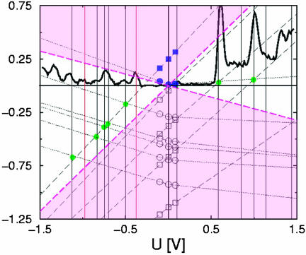
Fig. 8 shows the theoretical flow for the occupied levels together with the lowest unoccupied ones and a linear extrapolation to larger biases. The vertical lines indicate the theoretically expected peak positions that have to be compared with the experimental dI/dV data of the set-up Au–1′–Au.
Fig. 8.
Flow of the molecular energy levels corresponding to the fluorized (F-dot, circles) and unfluorized (H-dot, squares) sections of molecule 1′ when applying a finite bias voltage. The dashed lines (dashed, H-dot; dotted, F-dot) show linear extrapolations based on the numerical data, indicated by the open symbols. The black line represents the experimental differential I–V based on the data shown in Fig. 4. Black vertical lines display the theoretical peak positions defined by the crossing (green dot) of two extrapolated lines, and red lines indicate experimental peaks not reproduced. The white region between dashed lines in magenta marks the voltage window for observable crossings. The orbitals corresponding to the LUMOs of F-dot and H-dot (blue, filled symbols) are depicted in Fig. 7 for the case of vanishing voltage.
We find that our calculation gives a proper quantitative account of seven of the nine lowest-lying peaks with deviations not larger than the experimental peak width; only two peaks seen in the experiment are missing (indicated by red vertical lines in Fig. 8), and peaks predicted theoretically but not seen in the experiment are not observed.
Our calculation further suggests a mechanism for the observed pronounced asymmetry in the I–Vs. The slope of the level evolution is an indicator of the polarizability of the electron system. A small slope signalizes screening of the applied bias and points to a rather “metallic” character of the dot. In Fig. 8, the increased slopes of the H-dot levels (Fig. 8, squares) point at a more “insulating” character compared with the more “metallic” F-dot with flatter slopes. This theoretical observation is consistent with the higher zero-bias conductance of the more “metallic” junction Au–2′–Au consisting of two F-dots compared with the more “insulating” junction Au–3′–Au consisting of two H-dots.
Whereas slopes of the H-dot levels are more or less bias-independent, slopes of the F-dot are in general larger at negative bias, pointing to the asymmetric polarizability of the F-dot. In close similarity to a p-n junction, the current is larger in the forward direction, when the F-dot displays a larger polarizability. The experimentally observed tendency of larger currents but also larger spacing between peaks in one bias direction is a consequence of the fewer crossing events (with the H-dot levels) of the more conducting F-dot levels in the bias direction with flatter slopes.
Discussion
Although a qualitative agreement between data from the experiment and theory has been expected, the quantitative agreement is certainly somewhat fortunate. This is, for instance, because the exchange correlation functional used in the density functional theory (DFT) calculation is not exact, and, in general, deviations of the peak positions should be expected. Apparently, the approximation-induced changes in the level flow are quite small in the present case. Also, the experimental conditions cannot be controlled perfectly well on an atomistic scale, and, therefore, deviations from the model system used for the theoretical calculations may occur. Indeed, when the measurement is reproduced either by shaping a new molecular contact by opening and closing cycles or by using an entirely new bridge, the experimental curves look qualitatively similar but differ nevertheless.
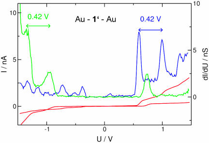
As an example, we present in Fig. 9 different I–Vs obtained with Au–1′–Au (red) and additionally its derivative dI/dV (green), where peaks correspond to the step-like features of the I–V. Evidently, the curve is inverted with respect to the bias direction, which can be immediately related to an oppositely oriented molecule. But the current steps have slightly different heights and are at different voltage positions. Several parameters in the contact and its environment are not controlled by our experiment: (i) The spatial orientation of the sample molecule. (ii) Different bonding types to the gold electrode may result in energy shifts (36), which shift the conductance peaks by a fraction of a volt. (iii) In addition, the environment may provide background charges, which effectively “dope” the molecule, resulting also in a shift of the peaks. Even though these parameters lead to different I–Vs, some characteristic features are common to all of them, which we assign to the specifics of the molecule. As can be seen in Fig. 9, the peak distance between the first two dominant peaks is unaffected. This observation agrees with our notion that the main effect of these uncontrolled parameters is to give a homogenous energy boost to the molecular levels with respect to the Fermi energy of the leads.
Fig. 9.
Another set of I–Vs obtained for Au–1′–Au (red), its numerical derivative dI/dV (green), and, for comparison, the derivative and the I–V shown in Fig. 4 (1). Clear differences between the two spectra can be attributed to experimental uncertainties, most obviously a different orientation of the sample molecule. Some general properties, in particular the peak distance, are unchanged.
In the original work of Aviram and Ratner (10), where incoherent transport was assumed, the rectification was a consequence of different thresholds at positive and negative bias: Whereas in one direction the threshold was low and current could flow already at small voltages, in the opposite direction there was no current at all below a much larger threshold. In our case the diode-like shape is more a consequence of different step heights of the current in positive and negative bias direction rather than their spacings (see Fig. 4). The D–σ–A concept used by Aviram and Ratner (10), however, remains useful also in our case if in a modified sense: The polarizability of a D–A system will in general depend on the direction of the applied electric field. Screening tends to be strong if the screening charge can move from the donor to the acceptor part of the molecule. It should tend to be weaker in the other case, where charges move back from the acceptor to the donor.
A further interesting intention of our experiment was also the direct comparison of the properties of the immobilized molecule 2′ and 3′. Because of the different amount of electron-pulling fluorine, a different charging state of the molecule would be expected upon contact, potentially observable as a systematic peak shift. Unfortunately, the present data did not give an unambiguous answer. The fluctuations in the threshold voltage from sample to sample are stronger than the systematic shift for the two molecules. Here, a much larger number of data would be needed to give a reliable result. However, the different shapes of the data with Au–2′–Au and Au–3′–Au, and also the qualitatively different behavior (with molecule 3, it was much more difficult to obtain stable contacts, probably because of the chemically more stable binding of the acetyl protection group to the unfluorinated thiophenol), may also point out that not only purely electronic effects may rule the phenomenology.
Summary
We have designed and synthesized a molecular rod with a donor and an acceptor unit that was designed to act as a diode when contacted from two sides. Indeed, single-molecule conductance measurements resulted in a diode-like shape of the I–Vs. Control experiments and a statistical evaluation of all available stable contacts provide convincing arguments that a single molecule was contacted in the desired way. The asymmetry results from different step heights of the current steps when the bias voltage is increased.
On the base of a detailed density functional theory (DFT) analysis of the molecule coupled to large gold clusters, we arrive at the following picture of transport. The molecule can be viewed as a system of two weakly coupled quantum dots that have different polarizabilities. In analogy to the physics of a p-n junction, this results in asymmetric bias dependence of the conductance. Our calculations are in good agreement with experimental findings.
Acknowledgments
We thank M. Hettler for helpful comments and discussions. This work was supported by the Strategiefond of the Helmholtz Foundation, the Volkswagen Foundation, and the network project MOLMEM of the German Ministry of Education and Research (Grant BMBF-FZK 13 N 8360).
Author contributions: F.E., H.B.W., and M.M. designed research; M.E., R.O., M.K., M.F., F.E., H.B.W., and M.M. performed research; M.E., R.O., M.K., M.F., C.v.H., F.W., F.E., H.B.W., and M.M. contributed new reagents/analytic tools; M.E., R.O., M.K., C.v.H., F.E., H.B.W., and M.M. analyzed data; and F.E., H.B.W., and M.M. wrote the paper.
This paper was submitted directly (Track II) to the PNAS office.
Abbreviations: A, acceptor; D, donor; MCB, mechanically controlled break junction.
Data deposition: The atomic coordinates have been deposited in the Cambridge Structural Database, Cambridge Crystallographic Data Centre, Cambridge CB2 1EZ, United Kingdom (CSD reference no. 241632).
Footnotes
11: a = 520.9(1), b = 1238.7(3), c = 2309.5(5) pm, α = 96.58(3), β = 90.77(3), γ = 97.75(3)°, V = 1466.4(5) × 106 pm3; triclinic  , Z = 2, ρcalc = 1.369 g/cm3, μ(MoKα) = 0,237 mm–1, STOE IPDS2, MoKα-radiation, λ = 0.71073 Å, T = 200 K, 2θmax = 52°; 6,316 reflections measured, 4,591 independent reflections (Rint = 0.0301), 3,232 independent reflections with Fobs > 4σ(Fobs). The structure was solved by direct methods and refined by full-matrix least square techniques against F2, 379 parameters (S, O, F, and C were refined anisotropically; H atoms were calculated at ideal positions); R1 = 0.0567; wR2 = 0.1737 (all data); Gof: 1.067; maximum peak, 0.238 eÅ–3. Cambridge Crystallographic Data Centre entry 241632 contains the crystallographic data for this paper.
|U| =1.5 V is a compromise of being well above the threshold voltage, which is affected by sample-to-sample fluctuations, and still being at a voltage, which allows for stable conditions for all junctions. The absolute current values scattered within a factor of two to three for all molecules. No correlation between the current level and the rectification ratios were observed.
References
- 1.Carroll, R. L. & Gorman, C. B. (2002) Angew. Chem. Int. Ed. 41 4378–4400. [DOI] [PubMed] [Google Scholar]
- 2.Mayor, M., Weber, H. B. & Waser, R. (2003) in Nanoelectronics and Information Technology. Advanced Electronic Materials and Novel Devices, ed. Waser, R. (Wiley, Weinheim, Germany), pp. 501–525.
- 3.Reed, M. A. & Tour, J. M. (2000) Sci. Am. 282 86–93. [DOI] [PubMed] [Google Scholar]
- 4.Joachim, C., Gimzewski, J. K. & Aviram, A. (2000) Nature 408 541–548. [DOI] [PubMed] [Google Scholar]
- 5.Barbara, P. F., Meyer, T. J. & Ratner, M. A. (1996) J. Phys. Chem. 100 13148–13168. [Google Scholar]
- 6.Balzani, V., ed. (2001) Electron Transfer in Chemistry (Wiley, Heidelberg).
- 7.Kuznetsov, A. M. & Ulstrup, J. (1998) Electron Transfer in Chemistry and Biology (Wiley, Heidelberg).
- 8.Kuhn, H. & Möbius, D. (1971) Angew. Chem. Int. Ed. Engl. 10 460–464. [Google Scholar]
- 9.Davis, W. B., Svec, W. A., Ratner, M. A. & Wasielewski, M. R. (1998) Nature 396 60–63. [Google Scholar]
- 10.Aviram, A., Ratner, M. A. (1974) Chem. Phys. Lett. 29 277–283. [Google Scholar]
- 11.Krzeminski, C., Delerue, C., Allan, G., Vuillaume, D. & Metzger, R. M. (2001) Phys. Rev. B 64 085405-1–085405-6. [Google Scholar]
- 12.Metzger, R. M. (1999) Acc. Chem. Res. 32 950–957. [Google Scholar]
- 13.Ng, M.-K. & Yu, L. (2002) Angew. Chem. Int. Ed. 41 3598–3601. [DOI] [PubMed] [Google Scholar]
- 14.Reichert, J., Ochs, R., Beckmann, D., Weber, H. B., Mayor, M. & von Löhneysen, H. (2002) Phys. Rev. Lett. 88 176804-1–176804-4. [DOI] [PubMed] [Google Scholar]
- 15.Kushmerick, J. G., Whitaker, C. M., Pollack, S. K., Schull, T. L. & Shashidar, R. (2004) Nanotechnology 15 S489–S493. [Google Scholar]
- 16.Larade, B. & Bratkovsky, A. M. (2003) Phys. Rev. B 68 235305-1–235305-8. [Google Scholar]
- 17.Stabel, A., Herwig, P., Müllen, K. & Rabe, J. P. (1995) Angew. Chem. Int. Ed. Engl. 34 303–307. [Google Scholar]
- 18.Chabinyc, M. L., Chen, X., Holmlin, R. E., Jacobs, H., Skulason, H., Frisbie, C. D., Mujica, V., Ratner, M. A., Rampi, M. A. & Whitesides, G. M. (2002) J. Am. Chem. Soc. 124 11730–11736. [DOI] [PubMed] [Google Scholar]
- 19.Kushmerick, J. G., Pollack, S. K., Yang, J. C., Naciri, J., Holt, D. B., Ratner, M. A. & Shashidhar, R. (2003) Ann. N.Y. Acad. Sci. 1006 277–290. [DOI] [PubMed] [Google Scholar]
- 20.Reed, M. A., Zhou, C., Muller, C. J., Burgin, T. P. & Tour, J. M. (1997) Science 278 252–254. [Google Scholar]
- 21.Kegueris, C., Bourgoin, J.-P., Palacin, S., Esteve, D., Urbina, C., Magoga, M. & Joachim, C. (1999) Phys. Rev. B 59 12505–12513. [Google Scholar]
- 22.Dulić, D., van der Molen, S. J., Kudernac, T., Jonkman, H. T., de Jong, J. J. D., Bowden, T. N., van Esch, J., Feringa, B. L. & van Wees, B. J. (2003) Phys. Rev. Lett. 91 207402-1–207402-4. [DOI] [PubMed] [Google Scholar]
- 23.Mayor, M., von Hänisch, C., Weber, H. B., Reichert, J. & Beckmann, D. (2002) Angew. Chem. Int. Ed. 41 1183–1186. [DOI] [PubMed] [Google Scholar]
- 24.Mayor, M., Weber, H. B., Reichert, J., Elbing, M., von Hänisch, C., Beckmann, D. & Fischer, M. (2003) Angew. Chem. Int. Ed. 42 5834–5838. [DOI] [PubMed] [Google Scholar]
- 25.Wenner, W. (1952) J. Org. Chem. 17 523–528. [Google Scholar]
- 26.Fuji, K., Yamada, T. & Fujita, E. (1981) Org. Magn. Res. 17 250–256. [Google Scholar]
- 27.Pollack, S. K., Naciri, J., Mastrangelo, J., Patterson, C. H., Torres, J., Moore, M., Shashidhar, R. & Kushmerick, J. G. (2004) Langmuir 20 1838–1842.15801452 [Google Scholar]
- 28.Jiang, P., Morales, G. M., You, W. & Yu, L. (2004) Angew. Chem. Int. Ed. 43 4471–4475. [DOI] [PubMed] [Google Scholar]
- 29.Topolski, M. (1995) J. Org. Chem. 60 5588–5594. [Google Scholar]
- 30.Suzuki, H. (1967) in Electronic Absorption Spectra and Geometry of Organic Molecules (Academic, New York), pp. 261–292.
- 31.Vaillancourt, F. H., Barbosa, C. J., Spiro, T. G., Bolin, J. T., Blades, M. W., Turner, R. F. B. & Eltis, L. D. (2002) J. Am. Chem. Soc. 124 2485–2496. [DOI] [PubMed] [Google Scholar]
- 32.Reichert, J., Weber, H. B., Mayor, M. & von Löhneysen, H. (2003) Appl. Phys. Lett. 82 4137–4139. [Google Scholar]
- 33.Tour, J. M., Jones, L. R., II, Pearson, D. L., Lamba, J. J. S., Burgin, T. P., Whitesides, G. M., Allara, D. L., Parikh, A. N. & Atre, S. V. (1995) J. Am. Chem. Soc. 117 9529–9534. [Google Scholar]
- 34.Treutler, O. & Ahlrichs, R. (1995) J. Chem. Phys. 102 346–354. [Google Scholar]
- 35.Eichkorn, K., Treutler, O., Ohm, H., Haser, M. & Ahlrichs, R. (1995) Chem. Phys. Lett. 240 283–289. [Google Scholar]
- 36.Evers, F., Weigend, F. & Köntopp, M. (2004) Phys. Rev. B 69 235411-1–235411-9. [Google Scholar]


