Abstract
Electron paramagnetic resonance (EPR) imaging is an advanced oxygen imaging modality for oxygen-image guided radiation. The iterative reconstruction algorithm is the research hot-point in image reconstruction for EPR imaging (EPRI) for this type of algorithm may incorporate image-prior information to construct advanced optimization model to achieve accurate reconstruction from sparse-view projections and/or noisy projections. However, the system matrix in the iterative algorithm needs complicated calculation and needs huge memory-space if it is stored in memory. In this work, we propose an iterative reconstruction algorithm without system matrix for EPRI to simplify the whole iterative reconstruction process. The function of the system matrix is to calculate the projections, whereas the function of the transpose of the system matrix is to perform backprojection. The existing projection and backprojection methods are all based on the configuration that the imaged-object remains stationary and the scanning device rotates. Here, we implement the projection and backprojection operations by fixing the scanning device and rotating the object. Thus, the core algorithm is only the commonly-used image-rotation algorithm, while the calculation and store of the system matrix are avoided. Based on the idea of image rotation, we design a specific iterative reconstruction algorithm for EPRI, total variation constrained data divergence minimization (TVcDM) algorithm without system matrix, and named it as image-rotation based TVcDM (R-TVcDM). Through a series of comparisons with the original TVcDM via real projection data, we find that the proposed algorithm may achieve similar reconstruction accuracy with the original one. But it avoids the complicated calculation and store of the system matrix. The insights gained in this work may be also applied to other imaging modalities, for example computed tomography and positron emission tomography.
Keywords: Iterative algorithm, System matrix, Image rotation, Optimization, EPR imaging
1. Introduction
Studies have shown that the oxygen concentration in the tumor has important impact on radiation efficiency [1]. Hypoxic (low oxygen concentration) regions in the tumor are resistant to radiation, requiring high-dose radiation, whereas hyperoxia (high oxygen concentration) regions are sensitive to radiation, requiring only low-dose radiation [2,3]. Obviously, tumor oxygen imaging is necessary for precise radiation based on oxygen concentration distribution. Electron paramagnetic resonance imaging (EPRI) is recognized as a high-resolution and accurate oxygen imaging modality [4]. Its spatial resolution can reach ~ 1 mm and oxygen concentration resolution can reach ~ 1 torr [5]. EPRI mainly has two forms: continuous wave EPRI [6,7] and pulsed EPRI. Pulsed EPRI has faster scanning speed [8], so it is the current mainstream.
Image reconstruction algorithms of 3D pulsed EPRI mainly include two types: analytical reconstruction method [9] and iterative reconstruction method. The analytical reconstruction method mainly refers to the 3D filtered backprojection (FBP) algorithm, which has fast reconstruction speed and therefore is the mainstream algorithm of the current commercial EPRI imager. Its disadvantage is that it requires complete projection data.
Similar to magnetic resonance imaging (MRI) [10], the bottleneck of EPRI is the too long scan process for collecting complete projections [11]. One way to achieve fast EPRI is to just collect sparse-view projections. However, images reconstructed from sparse-view projections by the analytical reconstruction method often suffer from severe streak artifacts, hindering their medical applications. Therefore, people began to explore iterative reconstruction methods in order to achieve accurate sparse reconstruction.
In 2014, Johnson et al. proposed a total variation (TV) minimization algorithm based on compressed sensing to achieve fast EPRI [12]. In 2015, Qiao et al. proposed a constrained, TV minimization reconstruction model, designed an adaptive steepest descent- projection onto convex set (ASD-POCS) algorithm to solve this model, and achieved accurate sparse reconstruction for pulsed EPRI [13]. In 2016, Christodoulou et al. proposed a dynamic EPRI reconstruction method based on low-rank tensors [14], which enabled fast scanning of dynamic imaging. In 2017, Durand et al. proposed a reconstruction algorithm based on TV and curvelets regularization to achieve accurate sparse reconstruction for continuous wave EPRI [15]. In 2018, Qiao et al. proposed a TV constrained, data divergence minimization (TVcDM) image reconstruction model and its Chambolle-Pock (CP) solving algorithm [16], achieving accurate sparse reconstruction for EPRI. In 2021, Qiao et al. proposed a balanced data divergence constrained, TV minimization-Chambolle-Pock (DDcTV-CP) image reconstruction algorithm [17], effectively solving the problem of slow convergence of the traditional DDcTV-CP algorithm for EPRI. All of these iterative reconstruction methods can achieve accurate EPRI reconstruction from sparse-view projections.
However, no matter which optimization model or solving algorithm is used, these reconstruction methods all involve the use of system matrix in the reconstruction process. The method of obtaining the system matrix is, in fact, the projection method, for the multiplication of the system matrix and the vectorized image is the vectorized projection. The existing projection methods in 3D EPRI mainly include the voxel-driven method [18] and the plane-driven method [13], both of which are approximations of the 3D Radon transform and require complex computing skills. Furthermore, if the system matrix is stored in memory, it will occupy a huge memory space and even cannot be stored. For example, if the size of the 3D image is 643 and the size of the projection data is also 643, then the size of the system matrix is 646 = 64G. If each element of the system matrix is represented by a double precision number, the matrix will require 512 GB memory space, which is not available in ordinary personal computer. Obviously, the calculation of the system matrix is complicated, and it is extremely huge and is difficult to store. If an iterative algorithm can be designed to avoid the use of the system matrix, it will undoubtedly greatly simplify the whole iterative reconstruction process.
We have noticed that the existing projection methods all adopt the mode in which the image remains stationary and the scanning mechanism rotates. In fact, we can adopt an opposite mode in which the image rotates and the scanning mechanism remains stationary. By use of this new mode, the projection operation will become very simple, that is, one only needs to rotate the image by the corresponding angle and project it at 0 angle. Similar operations may be used for backprojection. We have designed an iterative reconstruction method based on image rotation and applied it to 2D CT reconstruction to verify the performance of the method [19]. On this basis, this work will study the iterative reconstruction algorithm for 3D EPRI based on image rotation to avoid the use of system matrix.
In Section 2, we introduce the proposed algorithm. In Section 3, we compare the proposed algorithm with the traditional algorithm via real data. The discussion and conclusions are given in Section 4.
2. Methods
In this section, the continuous-continuous (CC)-data model, the discrete-discrete (DD)-data model, the plane-driven projection method, the rotation-driven projection and backprojection method, and the image rotation-based TVcDM-CP algorithm will be introduced.
2.1. Continuous-to-continuous (CC)-data model
The CC-data model of 3D EPRI is the 3D Radon transform. As shown in Fig. 1, the 3D Radon transform p(t, φ, θ) of 3D object f (x, y, z) can be formulated as.
Fig. 1.
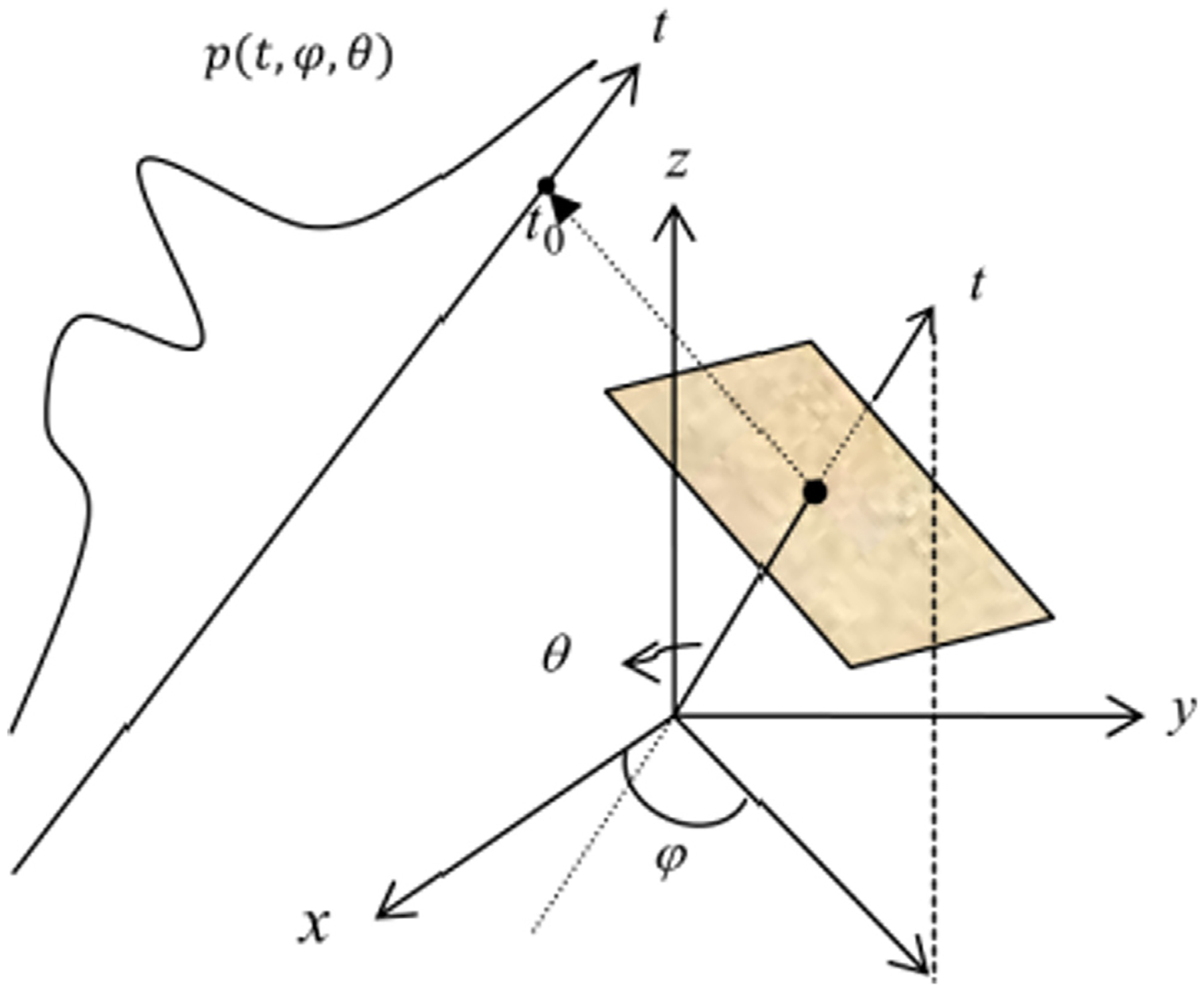
The schematic diagram of the 3D Radon transform.
| (1) |
Here, p(t, φ, θ) represents the area integral of the 3D object f (x, y, z) on the plane t = x cos φ sin θ + y sin φ sin θ + z cos θ, and δ(·) denotes the standard Dirac delta function. The projections should be distributed in the complete angle range, i. e. φ ∈ [0, 2π] and θ ∈ [0, π/2]. Here, θ is the angle between the z-axis and the t-axis, and φ is the angle between the x-axis and the projection axis of the t-axis on the xoy-plane. Obviously, this plane is perpendicular to the t-axis and the distance from the origin to the plane is t.
By fixing (φ, θ) and changing t, a 1D projection signal at this view-angle can be obtained. The set of 1D signals at all angles is the 3D Radon transform of the object. A series of parallel planes at a particular view-angle can be thought of a scan configuration at that angle. As view-angle (φ, θ) changes, the t-axis is rotating, as is the series of parallel planes. This data model is based on the mode in which the object remains stationary and the scan configuration (a series of parallel planes) rotates. In EPRI, the projection signal p(t, φ, θ) is obtained by performing the inverse Fourier transform (IFT) for each demodulated EPR signal, so it can be considered that the projection signal corresponds to a virtual detector. Each cell of the virtual detector corresponds to a specific plane, and the value of each cell is the area integral of the object on this plane. As shown in Fig. 1, p(t0, φ, θ) is the area integral corresponding to the light brown plane.
2.2. Discrete-to-Discrete (DD)-data model
By discretizing both the 3D object f (x, y, z) and the projection data p(t, φ, θ), we can obtain the dd-data model, which can be formulated as.
| (2) |
Here, g is a column vector of size M = np × na, representing discrete projection data, where na is the number of projection angles, and np is the number of sampling points of each 1D projection signal; u is a column vector of size N = nx × ny × nz, representing a discrete 3D image, where nx, ny, nz respectively denotes the number of voxels along the three dimensions of the 3D object; A is the system matrix of size M × N, representing 3D Radon transform. Therefore, Am,n represents the intersecting area between the plane corresponding to the m-th measurement of the object and the n-th voxel.
2.3. Plane-driven projection method
The method of obtaining the system matrix is the so-called projection method, because the multiplication of the system matrix and the image is the projection. According to the definition of Radon transform, the projection measurement is the area integral of the object. Therefore, when a 3D object is composed of discrete cubic voxels, a projection measurement is the sum of the product of the intersecting area between each voxel and the corresponding plane and the value of each voxel. Using this method to obtain the system matrix, the element Am,n of the system matrix is the intersecting area of the plane corresponding to the m-th measurement and the n-th voxel. This method to obtain projections is the so-called plane-driven projection method.
As shown in Fig. 2, the key to obtain the projection measurement corresponding to the yellow plane is to obtain the intersecting area of those cubes that intersect with the plane. A plane intersecting a cube may have triangular, quadrilateral, pentagon or hexagonal cross-section. We used this method when we carried out EPRI reconstruction in the early stage. However, the algorithm to obtain the intersecting area between a plane and a cube is very complex and requires careful handling of many special cases. Moreover, when we want to store the system matrix in memory, it will take up huge storage space. Especially, when the number of the image data and the projection data are both large, the system matrix even cannot be stored in memory. All of these are disadvantages of the plane-driven projection method. In other words, as long as the system matrix is used explicitly, there are always these disadvantages.
Fig. 2.
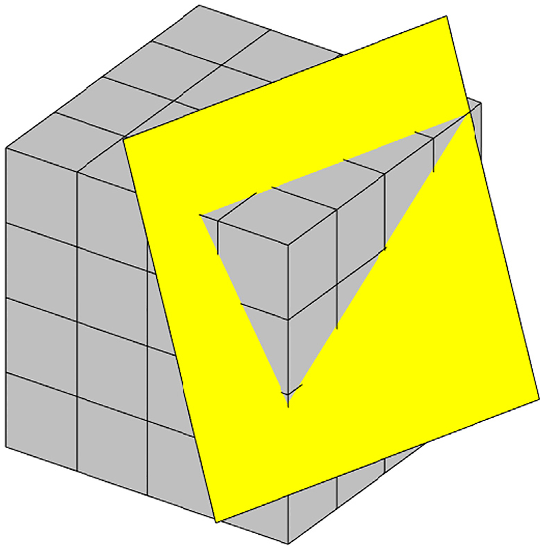
The schematic diagram of the 3D plane-driven projection method for 3D EPRI.
2.4. Rotation-driven projection method and back projection method
In order to avoid the complex calculation of system matrix, it is necessary to explore a new projection method, so that the projection can be obtained without explicit system matrix.
We note that the scanning mode on which the plane-driven method is based is that the object remains stationary and the scanning mechanism rotates. As shown in Fig. 3, the object remaining stationary and the scanning mechanism rotating is equivalent to the scanning mechanism remaining stationary and the object rotating. Thus, we can design a rotation-driven projection method.
Fig. 3.
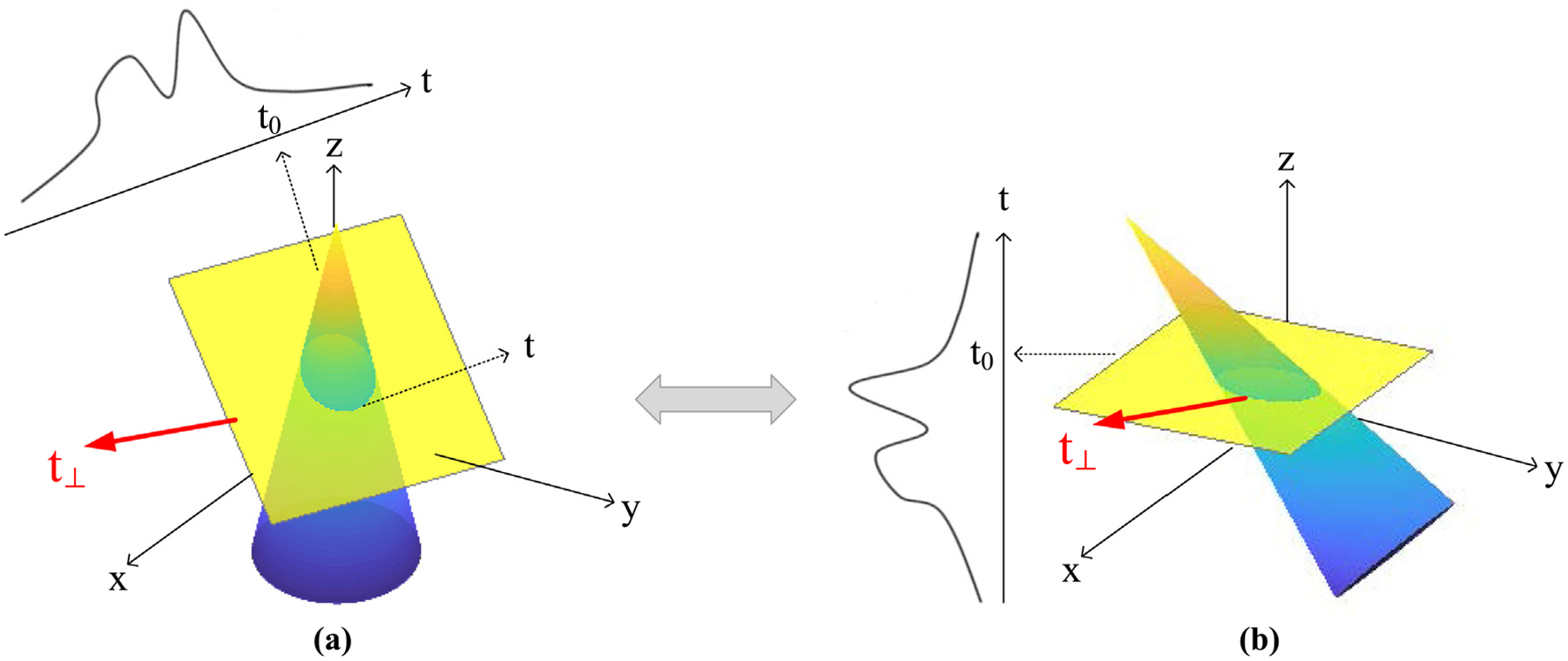
The schematic diagram showing that the object remaining stationary and the scanning mechanism rotating is equivalent to the scanning mechanism remaining stationary and the object rotating. (a) shows that the object remains stationary and the scanning mechanism rotates, and (b) shows that the scanning mechanism remains stationary and the object rotates.
We assume that the yellow plane in Fig. 3 (a) is the plane at the view-angle of (φ, θ) and at the distance of t0 from the origin, and its corresponding projection is the area integral on this plane. The plane may be regarded to be obtained by rotating the plane z = t0 clockwise by θ degrees around the rotation axis t⊥, which passes through the origin o and is perpendicular to the zot-plane. In Fig. 3 (b), the yellow plane is the plane z = t0. In this case, if the object is rotated counterclockwise by θ degrees around the rotation axis t⊥, the area integral on the plane is equivalent to that on the plane in Fig. 3 (a). Obviously, the object remaining stationary and the scanning mechanism rotating is equivalent to the scanning mechanism remaining stationary and the object rotating. The latter method of obtaining projections is the rotation-driven projection method.
The rotation-driven projection method is simple and does not require a system matrix. As shown in Fig. 4 (b), the projection corresponding to each plane is the sum of the voxel values in the layer. However, as shown in Fig. 4 (a), the plane-driven projection method needs to calculate the intersecting area between the plane and the voxels. The core operation of the rotation-driven method is just the common rotation of 3D objects, which greatly simplifies the calculation of projection. The pseudo-code of the rotation-driven projection method is shown in Table 1, where Na denotes the projection number.
Fig. 4.
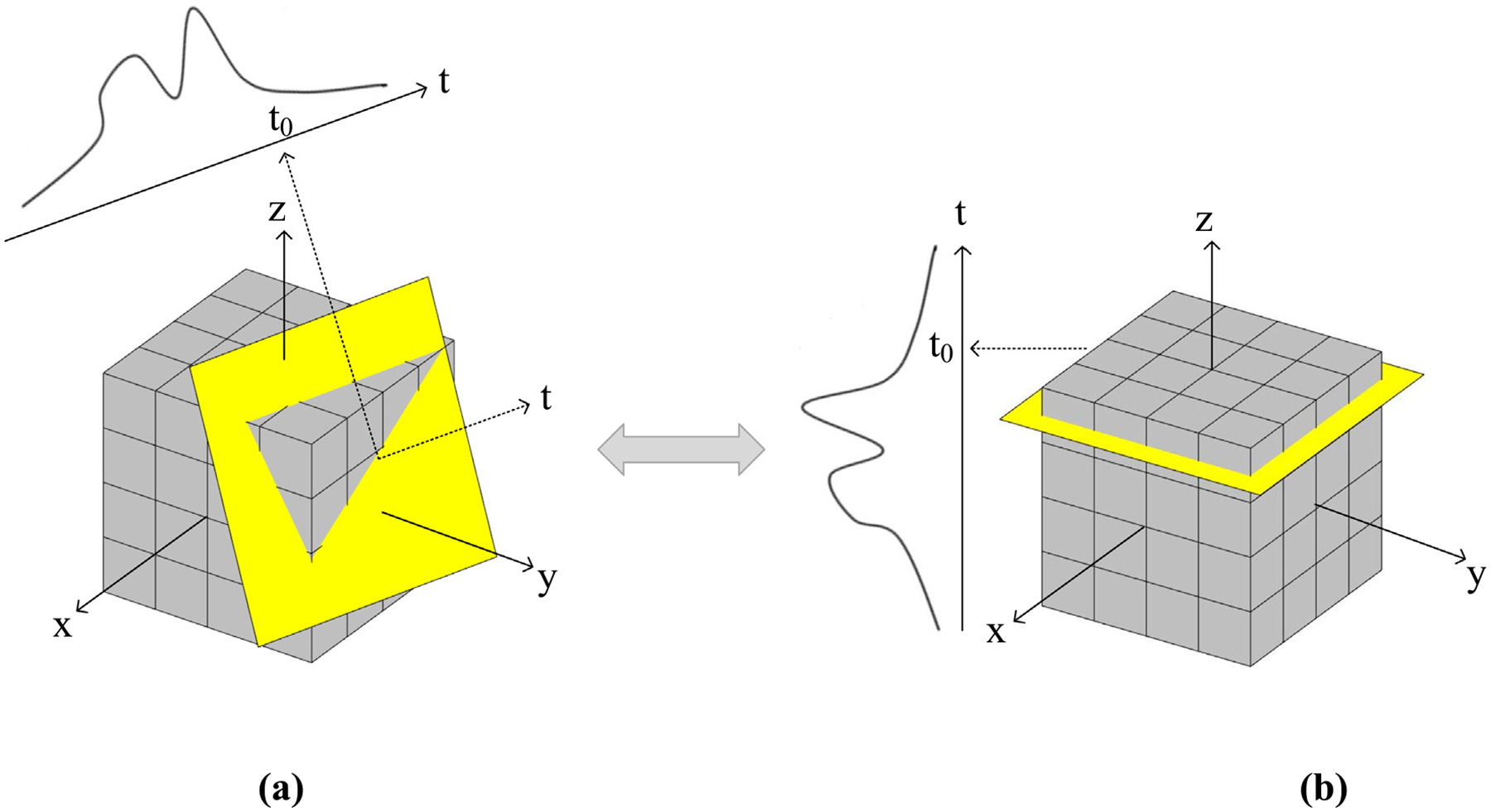
The schematic diagram of the plane-driven projection method (a) and the rotation-driven projection method (b).
Table 1.
Pseudo-codes of the rotation-driven projection method for 3D EPRI.
| INPUT : f (x, y, z) |
|---|
| 1: For k = 1 : Na |
| 2: get θk and φk . |
| 3: Calculate the direction vector of the rotation axis t⊥. |
| 4: Rotate the object f (x, y, z)forθk degree by anti-clockwise |
| 5: direction and get the rotated object R f (x, y, z). |
| 6: Sum up all the voxels layer by layer by the z axis direction and get the projection at angle (θk, φk), p(t, θk, φk). |
| 6: End |
| OUTPUT : p(t, φ, θ) |
The backprojection operation is the opposite operation of the projection operation. The difference is only that the backprojection is to let the voxel values of a certain layer of the object be the measurement value of the projection signal, whereas projection is to sum up all the voxel values of a certain layer. Therefore, the pseudo-code of the rotation-driven backprojection will not be repeated here.
2.5. TVcDM-CP algorithm and its image rotation-based version
In 2018, we have proposed the TVcDM-CP algorithm [16], which can achieve accurate sparse-view reconstruction in EPRI. In the iterative process of this algorithm, each iteration needs to calculate a projection and a back projection. At that time, we used a voxel-driven method [18] for projection and backprojection, which still required computing the system matrix. In order to verify the correctness of the rotation-driven projection and backprojection algorithms, we replace the operation Au in the pseudo-code of the algorithm with the rotation-driven projection operation, and replace the operation ATg with the rotation-driven backprojection operation, which forms an image rotation-based version of TVcDM-CP algorithm. We name it the R-TVcDM-CP algorithm. For the sake of brevity in the following discussion, we refer to the TVcDM-CP algorithm as the CP algorithm and the R-TVcDM-CP algorithm as the R-CP algorithm.
3. Results
In this section, we will compare the R-CP algorithm with the CP algorithm via real data. If the accuracy is similar, it is verified that the rotation-driven projection method without system matrix and its backprojection method, which are proposed in this work, are correct.
3.1. Imager specifications
As shown in Fig. 5 (a), we use a pulsed EPRI imager to scan objects. It is a JIVA-25 EPRI oxygen imager for small animals, produced by O2M Technologies in the United States, whose specifications are shown in Table 2.
Fig. 5.
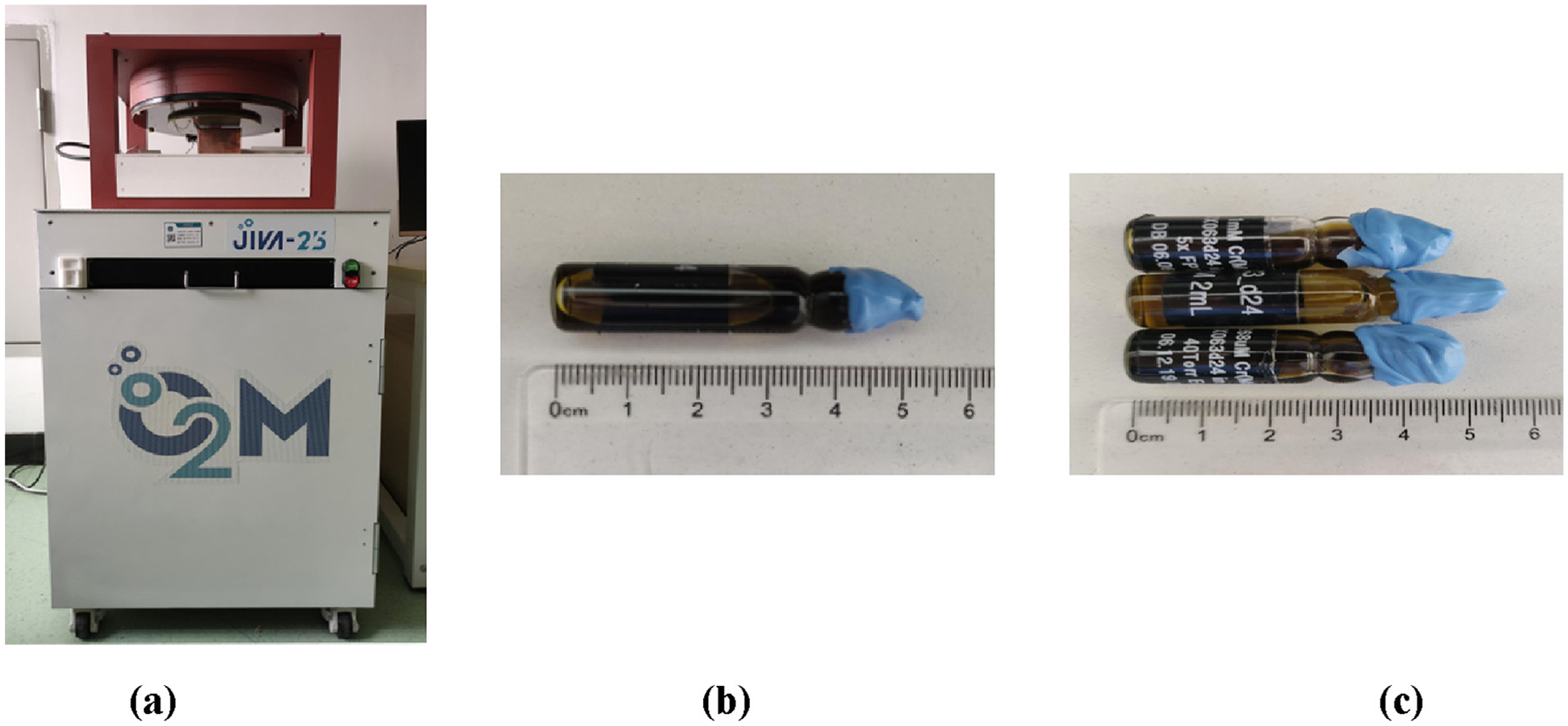
(a) shows the JIVA-25 EPRI oxygen imager for small animals; (b) and (c) show some physical phantoms containing spin probes. The spin probe is OX063-d24. The concentration of the phantom solution in (b) is 1 mM, and that in (c) is 1 mM, 0.5 mM and 0.268 mM, respectively.
Table 2.
Specification of the EPR oxygen imager.
| Main magnetic field strength | 250G |
|---|---|
| Maximal gradient magnetic field strength | 30mT/m |
| Radio-frequency signal frequency | 720 MHz |
| Size of resonator | Φ 25 mm × 35 mm |
| Depth of detection | 50 mm |
| Spatial resolution | <1mm |
| Oxygen concentration resolution | 1 torr |
| Gx direction | To the top |
| Gy direction | To the right |
| Gz direction | To the rear |
3.2. The reconstruction of a standard physical phantom
3.2.1. The imaging configurations
As shown in Fig. 5 (b), a standard physical phantom is a small bottle containing trityl solution. Trityl is an EPRI spin probe, per molecule of which has an unpaired electron, enabling electron paramagnetic resonance. The size of the reconstructed 3D object is 64 × 64 × 64 and the lengths of the three dimensions are all . Therefore, the side length of each voxel is 0.0663 cm. The origin of the imaging coordinate system is at [32, 32, 32]. The length of the virtual detector is also , and the number of virtual detector cells is also 64. Therefore, the length of each virtual detector cell is also 0:0663cm. We collects a total of 208 projections from different views to form complete projections. These projections are sampled using an equal-solid-angle pattern [20], so the distribution of the sampling views is approximately uniform. In order to evaluate the sparse-view reconstruction ability of the algorithm, we sample sparse-view projections with an approximately uniform distribution from 208 complete projections to form sparse-view projection sets using the maximally spaced projection sequencing (MSPS) method [21]. The numbers of projections in these sparse-view projection sets are 50, 80, 110, 140, and 170, respectively.
For the imager we used, the spatial resolution is about 1 mm. Now, the voxel is of side-length 0.663 mm, so this setup is enough for achieving the physical spatial resolution. To achieve this resolution, the spatial resolution of the virtual detector should be also smaller than 1 mm. Here, the virtual detector cell is of size 0.663 mm and is small enough. In fact, we may let the size of the virtual detector cell be smaller than the voxel-side-length. However, it cannot improve the reconstruction accuracy no matter in analytic algorithm [9]or in iterative algorithm [16]. Thus, we set the size of the virtual detector cell be also 0.663 mm. In addition, the equivalence of the voxel-side-length and the size of the virtual detector cell may simplify the design of voxel-driven and rotation-driven projection and backprojection operations.
3.2.2. The reconstructed results
Using the method in [16] to determine the model parameter t1, we set t1 = 0.2t0 for the R-CP algorithm and t1 = 0.15t0 for the CP algorithm to obtain the reconstruction with the best accuracy respectively, where t0 is the TV value of image reconstructed by the FBP method.
When the number of projection views Na is set to 50, 80, 110, 140, 170 and 208, respectively, the results reconstructed by the FBP, CP and R-CP algorithms are shown in Fig. 6. It can be seen that all the images reconstructed by the FBP algorithm suffer from streak artifacts, and as the number of projections decreases, the artifacts become more and more obvious. However, in the images reconstructed by the CP algorithm and the R-CP algorithm, the artifacts are effectively suppressed. In particular, the image reconstructed by the FBP algorithm from 50 views projections has serious deformation, while the CP algorithm and the R-CP algorithm can reconstruct the images well. It is worth noting that the images reconstructed by the R-CP and CP algorithms are very similar and indistinguishable to the naked eye, which indicates that the reconstruction accuracy of the two algorithms is similar.
Fig. 6.
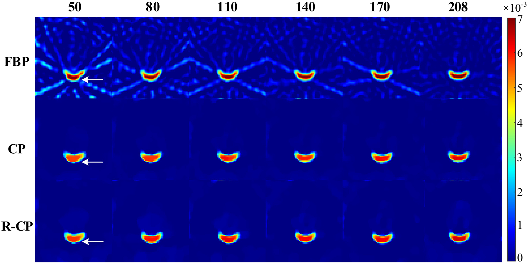
The reconstructed images of the standard physical phantom. The number above the images is the number of projections and the text at the left of the images indicates the reconstruction algorithms used. The display window is [0, 0.007].
For quantitative assessment, we use the reference-image-based normalized object error (rNOE) [11] as the metric to assess the quality of reconstructed images, which is defined by Eq. (14) in [11]. The smaller the rNOE value of the reconstructed image, the better the quality of the image, and the higher the reconstruction accuracy of the corresponding algorithm.
Fig. 7 plots the rNOE of the corresponding reconstructed images in Fig. 6. It can be seen that in the case of any number of projections, the rNOE values of the images reconstructed by the R-CP and the ones by the CP are both lower than those by the FBP, which indicates that the two optimization-based algorithms can achieve higher accuracy than the FBP algorithm. The rNOE of the images reconstructed by the CP is slightly lower than that by the R-CP, but their accuracy is similar, indicating that both the projection and the backprojection in the R-CP algorithm for the reconstruction of the standard physical phantom are correct.
Fig. 7.
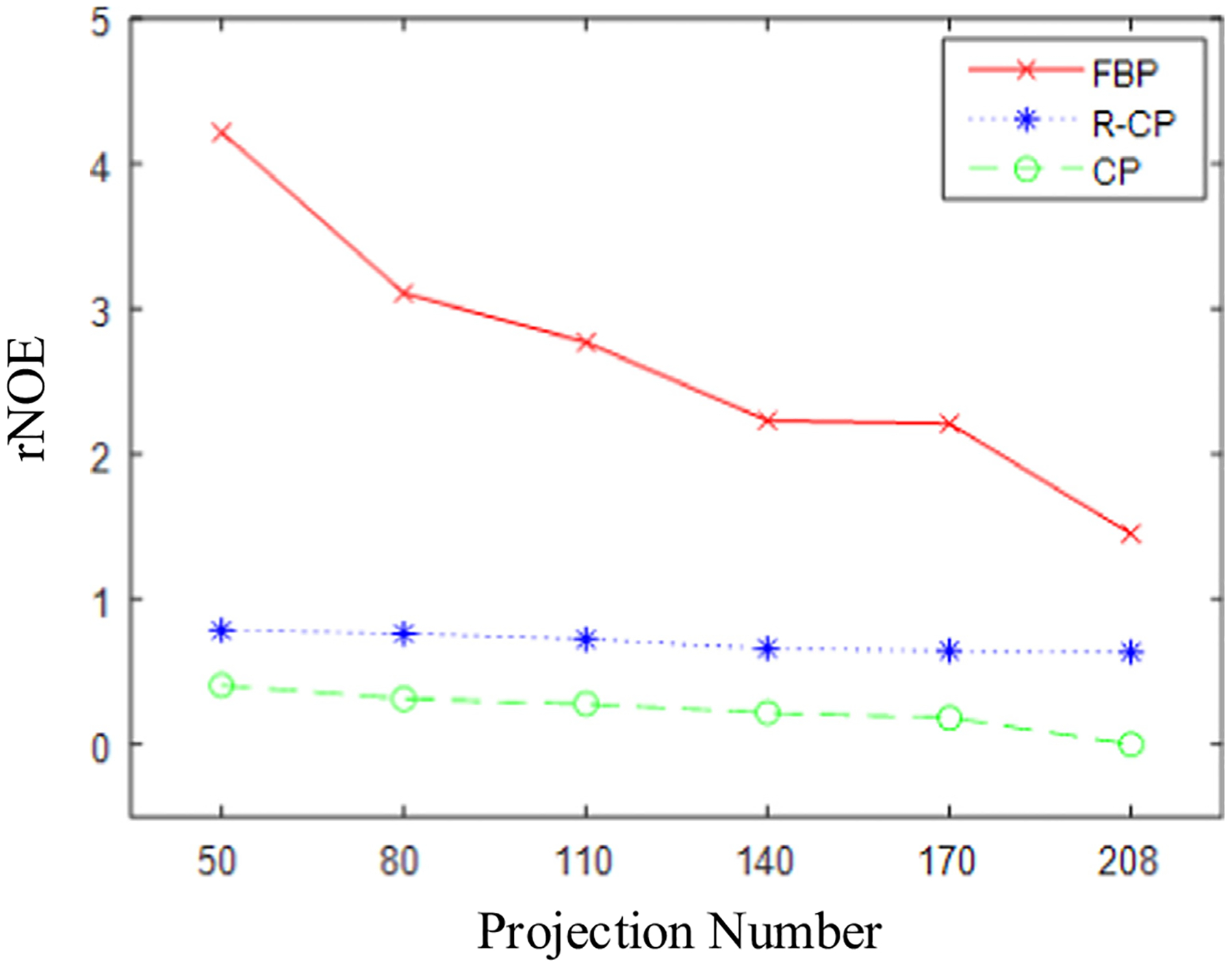
Plots of rNOE of the reconstructed images of the standard physical phantom as functions of projection number.
3.3. The reconstruction of a complex physical phantom
3.3.1. The imaging configurations
The complex physical phantom is composed of three small bottles containing trityl solution, as shown in Fig. 5 (c). It should be noted that the three bottles are stacked when it is placed in the resonator. The imaging configurations used for this phantom are the same as those for the standard physical phantom.
3.3.2. The reconstructed results
We set t1 = 0.4t0 for the R-CP algorithm and set t1 = 0.5t0 for the CP algorithm to achieve accurate reconstructions. The reconstructed results of the complex physical phantom are shown in Fig. 8.
Fig. 8.
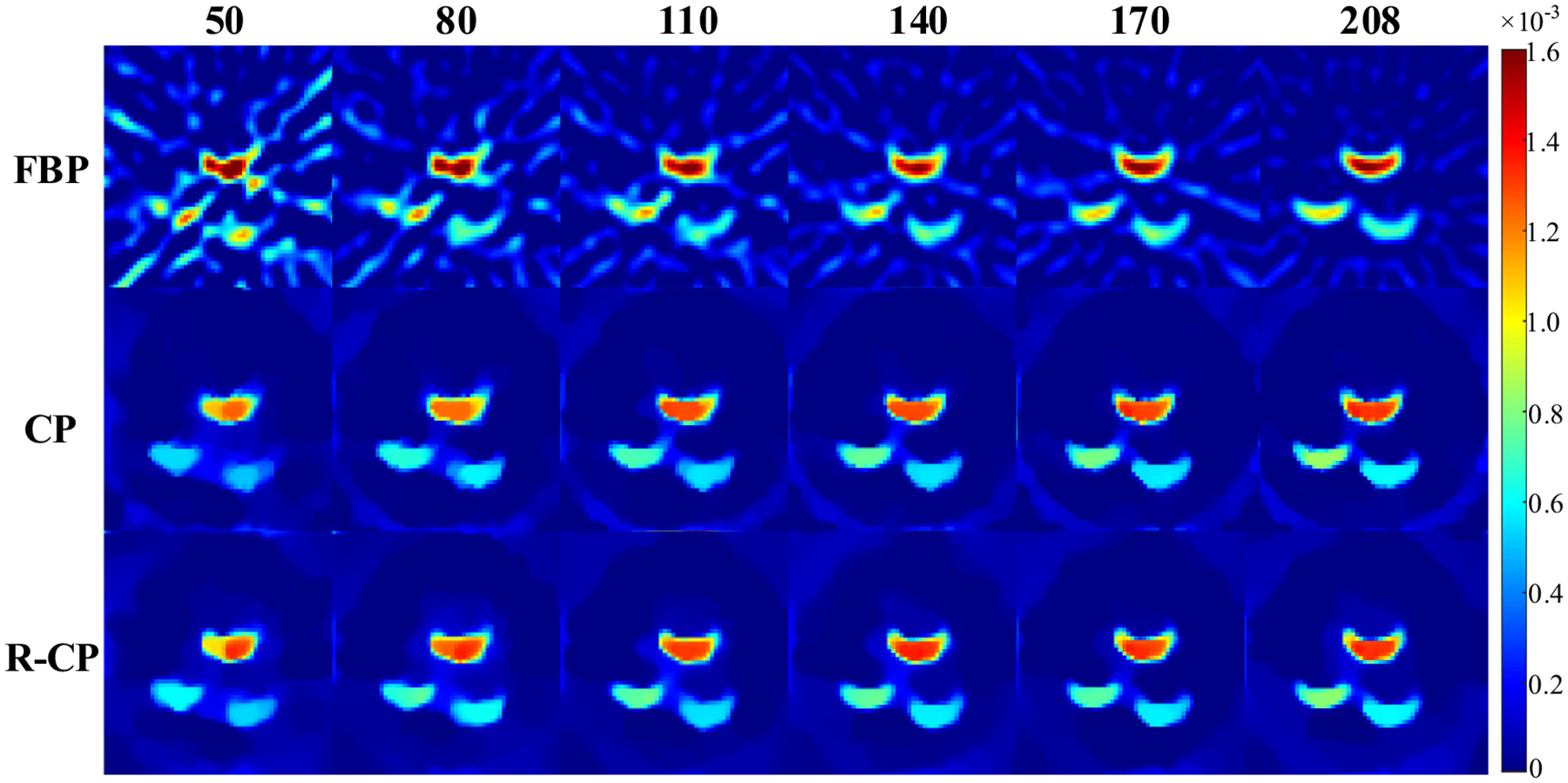
The reconstructed images of the complex physical phantom. The number above the images is the number of projections and the text at the left of the images indicates the reconstruction algorithms used. The display window is [0, 0.0016].
It can be seen from Fig. 8 that all the images reconstructed by the FBP algorithm suffer from streak artifacts, and as the number of projections decreases, the artifacts become more and more obvious. However, the CP algorithm and the R-CP algorithm can effectively suppress the artifacts. Moreover, for the complex physical phantom imaging, the two algorithms based on optimization are both better than the FBP in suppressing image deformation. Therefore, the accuracy of the two reconstruction algorithms, the R-CP and the CP, based on optimization is much higher than that of the FBP algorithm. At the same time, the reconstruction accuracy of the R-CP algorithm and that of the CP algorithm are similar, and it is difficult for the naked eye to distinguish each other.
Fig. 9 plots the rNOE of the reconstructed images in Fig. 8. It can be seen that in the case of any number of projections, the rNOE values of the images reconstructed by R-CP and the ones by CP are both lower than those by the FBP, which indicates that both of the two optimization-based algorithms can achieve higher accuracy than the FBP. The rNOE of the images reconstructed by the CP is slightly lower than that by the R-CP, but their accuracy is similar, indicating that both the projection and the backprojection operations in the R-CP algorithm are correct. We think the reason why the accuracy of R-CP algorithm is slightly lower than that of CP is that the projection and backprojection operations of R-CP are not exactly matched [22]. However, the experiments show that the accuracy of the R-CP algorithm is high enough to support real data reconstructions.
Fig. 9.
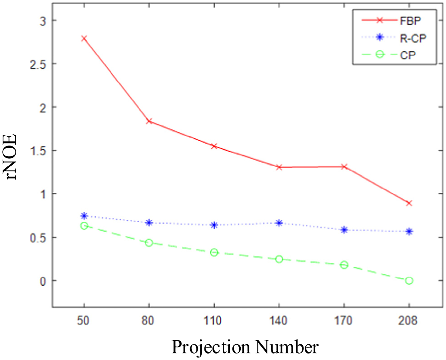
Plots of rNOE of the reconstructed images of the complex physical phantom as functions of projection number.
4. Discussion and conclusions
In this work, we propose an image-rotation-based iterative reconstruction algorithm for EPRI, which may avoid the complicated calculation of system matrix. The function of system matrix is to perform projection operation and the function of its transpose matrix is to perform backprojection operation. Based on the image-rotation technique, the projection and backprojection operations become very easy for their core operation is just the commonly-used image-rotation operation.
In fact, the success of the proposed method is based on the observation that fixing the image and rotating the scanning device is equivalent with fixing the scanning device and rotating the image. The existing projection and backprojection algorithms for EPRI include the voxel-driven method and the plane-driven method. They both need to calculate the contribution of a voxel to a measurement. That is to say they both need to calculate the system matrix. On the one hand, these methods are complicated and need advanced computational technique. On the other hand, the system matrix will need huge memory space if it is stored in memory. Both the voxel-driven method and the plane-driven method are based on fixing image and rotating the scanning device. Equivalently but skillfully, we propose this image-rotation-based projection and backprojection method that do not need the calculation of system matrix. The real data experiments have demonstrated the correctness and effectiveness of this method. We may regard the proposed projection and backprojection method as rotation-driven method, which is simpler than the voxel-driven and plane-driven methods but may achieve comparable reconstruction accuracy with the other two methods in the iterative reconstruction algorithms. The projection and backprojection technique without system matrix can be exploited for simplifying the whole iterative reconstruction process and enabling fast EPR imaging. Thus, we get a new, simple, but effective projection and backprojection method in EPRI.
In addition, this image-rotation-based projection and backprojection method may also be transplanted to other imaging modalities. For example, in fan-beam and cone-beam CT, one may just calculate a small system matrix corresponding to the projection and backprojection operations at the starting view then apply the rotation technique to calculate all the other projections and backprojections. For 4D EPRI, the hyper-plane-driven projection method will be very complicated for it needs to calculate the intersecting volume of a hyper-plane and a hyper-voxel. But, if one uses the proposed image-rotation technique, whose core operation is just the 4D image-rotation that is not difficult. The insights gained in this work may be also used in the iterative reconstruction algorithms without system matrix for other imaging modalities, such as, CT and positron emission tomography (PET).
Funding
This work was supported in part by National Natural Science Foundation of China under grant 62071281, by Local Science and Technology Development Fund Project Guided by the Central Government under grant YDZJSX2021A003, by Research Project Supported by Shanxi Scholarship Council of China under grant 2020-008, and by the NIH under grants P41 EB002034 and R01 CA098575.
Footnotes
Declaration of Competing Interest
The authors declare that they have no known competing financial interests or personal relationships that could have appeared to influence the work reported in this paper.
Data availability
Data will be made available on request.
References
- [1].Epel B, Maggio MC, Barth ED, Miller RC, Pelizzari CA, Krzykawska-Serda M, Sundramoorthy SV, Aydogan B, Weichselbaum RR, Tormyshev VM, Halpern HJ, Oxygen-guided radiation therapy, Int. J. Radiat. Oncol 103 (2019) 977–984. [DOI] [PMC free article] [PubMed] [Google Scholar]
- [2].Epel B, Kotecha M, Halpern HJ, In vivo preclinical cancer and tissue engineering applications of absolute oxygen imaging using pulse EPR, J. Magn. Reson 280 (2017) 149–157. [DOI] [PubMed] [Google Scholar]
- [3].Brizel DM, Sibley GS, Prosnitz LR, Scher RL, Dewhirst MW, Tumor hypoxia adversely affects the prognosis of carcinoma of the head and neck, Int. J. Radiat. Oncol 38 (1997) 285–289. [DOI] [PubMed] [Google Scholar]
- [4].Kuppusamy P, Wang P, Zweier JL, Krishna MC, Mitchell JB, Ma L, Trimble CE, Hsia CJC, Electron paramagnetic resonance imaging of rat heart with nitroxide and polynitroxyl-albumint, Biochemistry 35 (1996) 7051–7057. [DOI] [PubMed] [Google Scholar]
- [5].Matsumoto K-I, Subramanian S, Devasahayam N, Aravalluvan T, Murugesan R, Cook JA, Mitchell JB, Krishna MC, Electron paramagnetic resonance imaging of tumor hypoxia: Enhanced spatial and temporal resolution for in vivo pO2 determination, Magn. Reson. Med 55 (2006) 1157–1163. [DOI] [PubMed] [Google Scholar]
- [6].Matsumoto K-I, Chandrika B, Lohman JAB, Mitchell JB, Krishna MC, Subramanian S, Application of continuous-wave EPR spectral-spatial image reconstruction techniques for in vivo oxymetry: Comparison of projection reconstruction and constant-time modalities, Magn. Reson. Med 50 (2003) 865–874. [DOI] [PubMed] [Google Scholar]
- [7].Epel B, Haney CR, Hleihel D, Wardrip C, Barth ED, Halpern HJ, Electron paramagnetic resonance oxygen imaging of a rabbit tumor using localized spin probe delivery, Med. Phys 37 (2010) 2553–2559. [DOI] [PMC free article] [PubMed] [Google Scholar]
- [8].Epel B, Sundramoorthy SV, Barth ED, Mailer C, Halpern HJ, Comparison of 250 MHz electron spin echo and continuous wave oxygen EPR imaging methods for in vivo applications, Med. Phys 38 (2011) 2045–2052. [DOI] [PMC free article] [PubMed] [Google Scholar]
- [9].Qiao Z, Redler G, Epel B, Halpern HJ, Comparison of parabolic filtration methods for 3D filtered back projection in pulsed EPR imaging, J. Magn. Reson 248 (2014) 42–53. [DOI] [PMC free article] [PubMed] [Google Scholar]
- [10].Block KT, Uecker M, Frahm J, Undersampled radial MRI with multiple coils. Iterative image reconstruction using a total variation constraint, Magn. Reson. Med 57 (2007) 1086–1098. [DOI] [PubMed] [Google Scholar]
- [11].Qiao Z, Liang D, Tang S, Halpern HJ, Optimization-based image reconstruction from fast-scanned, noisy projections in EPR imaging, IEEE Access 7 (2019) 19590–19601. [Google Scholar]
- [12].Johnson DH, Ahmad R, He G, Samouilov A, Zweier JL, Compressed sensing of spatial electron paramagnetic resonance imaging, Magn. Reson. Med 72 (2014) 893–901. [DOI] [PMC free article] [PubMed] [Google Scholar]
- [13].Qiao Z, Redler G, Epel B, Qian Y, Halpern HJ, 3D pulse EPR imaging from sparse-view projections via constrained, total variation minimization, J. Magn. Reson 258 (2015) 49–57. [DOI] [PMC free article] [PubMed] [Google Scholar]
- [14].Christodoulou AG, Redler G, Clifford B, Liang Z, Halpern HJ, Epel B, Fast dynamic electron paramagnetic resonance (EPR) oxygen imaging using low-rank tensors, J. Magn. Reson 270 (2016) 176–182. [DOI] [PMC free article] [PubMed] [Google Scholar]
- [15].Durand S, Frapart Y-M, Kerebel M, Electron paramagnetic resonance image reconstruction with total variation and curvelets regularization, Inverse Probl. 33 (2017). [Google Scholar]
- [16].Qiao Z, Zhang Z, Pan X, Epel B, Redler G, Xia D, Halpern HJ, Optimization-based image reconstruction from sparsely sampled data in electron paramagnetic resonance imaging, J. Magn. Reson 294 (2018) 24–34. [DOI] [PubMed] [Google Scholar]
- [17].Qiao Z, Redler G, Epel B, Halpern HJ, A balanced total-variation-Chambolle-Pock algorithm for EPR imaging, J. Magn. Reson 328 (2021). [DOI] [PubMed] [Google Scholar]
- [18].Qiao Z, Redler G, Gui Z, Qian Y, Epel B, Halpern HJ, Three novel accurate pixel-driven projection methods for 2D CT and 3D EPR imaging, J. X-ray Sci. Tech 26 (2018) 83–102. [DOI] [PubMed] [Google Scholar]
- [19].Qiao Z, Lu Y, A TV-minimization image-reconstruction algorithm without system matrix, J. X-ray Sci. Tech 29 (2021) 851–865. [DOI] [PubMed] [Google Scholar]
- [20].Ahn K-H, Halpern HJ, Spatially uniform sampling in 4-D EPR spectral-spatial imaging, J. Magn. Reson 185 (2007) 152–158. [DOI] [PMC free article] [PubMed] [Google Scholar]
- [21].Redler G, Epel B, Halpern HJ, Maximally spaced projection sequencing in electron paramagnetic resonance imaging, Concepts Magn, Reson. Part B: Magn. Reson. Eng 45 (2015) 33–45. [DOI] [PMC free article] [PubMed] [Google Scholar]
- [22].Zeng GL, Gullberg GT, Unmatched projector/backprojector pairs in an iterative reconstruction algorithm, IEEE transactions on medical imaging 19 (2000) 548–555. [DOI] [PMC free article] [PubMed] [Google Scholar]
Associated Data
This section collects any data citations, data availability statements, or supplementary materials included in this article.
Data Availability Statement
Data will be made available on request.


