

Abstract
Additive manufacturing (AM), also known as 3D printing, is a recent innovation in manufacturing, employing additive techniques rather than traditional subtractive methods. This study focuses on Directed Energy Deposition (DED), utilizing a blend of nickel-based superalloy IN 718 and stainless steel SS316 powders in varying ratios (25%+75%, 50%, and 75%+25%). The objective is to assess the impact of process parameters on quality and optimize them. Mechanical properties of the different powder mixtures are compared. In the study, Taguchi-grey relational analysis is employed for parameter optimization, with four key factors identified: laser power, overlap ratio, powder feed rate, and scanning speed, affecting cladding efficiency, deposition rate, and porosity. Verification experiments confirm optimization repeatability, and further fine-tuning is achieved through one-factor-at-a-time experiments. Optimized parameters yield varied tensile properties among different powder mixtures; for example, a 25% SS316L and 75% IN718 blend demonstrates the highest ultimate tensile strength (499.37 MPa), while a 50% SS316L and 50% IN718 blend exhibits the best elongation (13.53%). This study offers an effective approach for using DED technology to create mixed SS316 and IN718 powders, enabling tailored mechanical performance based on mixing ratios.
Keywords: Directed energy deposition, Taguchi experimental design method, Multi-materials, Grey relational analysis and process parameter optimization
Subject terms: Engineering, Materials science
Introduction
DED is a metal additive manufacturing technology. It uses powder feeding gas to transport metal powder to the energy center of heat source and the melt powder directly deposited on a substrate or surface of an unfinished part. By repeating the deposition layer by layer, a 3D product can be fabricated by DED. DED has many advantages such as short production period, customized production, material saving and the ability to produce parts with complex geometry. Using metal materials also makes DED products have great mechanical properties, fatigue, high temperature and corrosion resistances. These advantages let DED gradually be used in national defense, aerospace, transportation and other fields in recent years. However, DED is a complex process and there are many control factors that can affect product qualities. Therefore, how to stabilize the DED process and select the appropriate control factor setting in order to reduce dimensional errors, processing time and maintain mechanical strength are the critical goals of DED research.
In the DED process, IN718 and SS316L are commonly used metal materials, each with distinct characteristics. IN718 has excellent high-temperature performance and corrosion resistance, making it suitable for aerospace engines and gas turbines. SS316L, on the other hand, is known for its good corrosion resistance and weldability, making it widely used in chemical, medical, and food processing industries. However, when used individually, both materials face challenges in terms of processing difficulty and performance limitations. Therefore, mixing these two materials combines their respective advantages, overcoming limitations and achieving greater flexibility in forming and application. This has become a growing international trend in recent years. Currently, research on the hybrid manufacturing of IN718 and SS316L is still limited, and the same process parameters are often used internationally, without considering the impact of different parameters on product quality. This study aims to explore the optimal process factors for the hybrid manufacturing of IN718 and SS316L to achieve ideal mechanical properties and performance. Through systematic research and comparison of process parameters, material composition, and mechanical properties, this study provides valuable reference and experience for hybrid manufacturing in the DED process.
The purpose of choosing the Taguchi experimental analysis method is to find the optimal process parameters for the two different materials. This method effectively reduces the number of experiments and time costs while systematically organizing the best process parameters for multi-factor control. However, the limitation of the Taguchi method is that it cannot adjust the relative importance of control factors, as all factors are given equal weight. Therefore, by combining grey relational analysis, the significance of key factors can be adjusted based on the importance of product quality goals, enabling more precise optimization of the process parameters. In this combined approach, the Taguchi method provides robustness and multi-factor analysis advantages, while grey relational analysis optimizes for multiple quality objectives, ensuring the best quality and performance under various parameter conditions.
The purpose of this study is to perform factor combination optimization experiments on three different mixing ratios using the Taguchi grey relational analysis method. The cladding efficiency, porosity, and deposition rate are used as the quality objectives for optimization in this DED study. The controlled factors are laser power, overlap ratio, powder feed rate, and scanning speed. In the context of the multi-layer and multi-track DED process, optimization is conducted simultaneously for the three product quality objectives—cladding efficiency, porosity, and deposition rate—to identify the optimal factor combination within the specified operating range. Regarding the differences in mechanical properties exhibited by the three ratios, this study utilizes the optimal process factor combinations obtained from the Taguchi grey relational experiments as process parameters. Tensile testing experiments are conducted to compare the mechanical properties of the workpieces with different mixing ratios.
This study aims to enhance the composite material’s resistance to corrosion, strength, and temperature stability. In the future, it is anticipated that this improvement can be applied to components related to aerospace and gas turbine parts, significantly reducing the costs associated with component repairs.
Materials and methods
Equipment and materials
In this study, an IPG YLS-3000 fiber laser was utilized, operating at a wavelength of 1070 nm and a maximum power output of 3000 W. The laser spot had a diameter of 3 mm with a uniform energy distribution. A Precitec YC30 laser head with coaxial four-way powder feeding capability was employed, featuring an adjustable hub to control the laser’s focal position. Metal powder was delivered to the laser head using a GTV PF 2/2 LC powder feeder, which operated with a rotating powder disk. The feeding rate was measured at 10.08 g/min per 1 rpm, which is 8.064 g/min, as calculated in (1). The laser head was mounted on a Tongtai TMV-710 A machine tool, which is equipped with dual rotary axes and capable of performing simultaneous five-axis movements.
 |
1 |
The powder materials used in this study were nickel-based superalloy IN 7181–3 and AISI 316 L. The substrate materials were AISI 316 L. The particle size distribution range of the powder was 53–150 μm. The IN718 powder was produced by gas atomization, and its particle size distribution, measured using a Mastersizer laser particle size analyzer, ranges from 53 to 150 μm. The detailed particle size distribution analysis results are shown in Table 1. The powder composition was analyzed using Inductively Coupled Plasma Atomic Emission Spectroscopy (ICP-OES) and a Carbon & Sulfur Analyzer (C/S Analyzer), with the results shown in Table 2.The SS316 powder was also produced by gas atomization, and its particle size distribution, measured with a Laser Particle Size Analyzer, ranges from 53 to 150 μm. The detailed particle size distribution analysis results are shown in Table 3. The composition of the SS316 powder was analyzed using Inductively Coupled Plasma (ICP), a Carbon & Sulfur Analyzer, and a Nitrogen & Oxygen Analyzer, with the results shown in Table 4.
Table 1.
Composition of the SS316L powder.
| Diameter distribution (µm) | C% | Si% | Fe% | Cr% | Ni% | Mo% | Mn% | |
|---|---|---|---|---|---|---|---|---|
| SS316L | 53–150 | ≤ 0.03 | 0.8 | Bal. | 17.0 | 12.0 | 2.5 | 1.5 |
Table 2.
Size of the SS316L powder.
| Particle size | 53–100 μm |
|---|---|
| Distribution | D10 = 61.38 μm, D50 = 91.64 μm, D90 = 132.6 μm |
Table 3.
Composition of the IN718 powder.
| Diameter distribution (µm) | C% | Nb% | Fe% | Cr% | Ni% | Mo% | Ti% | |
|---|---|---|---|---|---|---|---|---|
| SS316L | 53–150 | ≤ 0.03 | 5.0 | Bal. | 17.8 | 52.5 | 3.0 | 1.0 |
Table 4.
Size of the IN718 powder.
| Particle size | 53–100 μm |
|---|---|
| Distribution | D10 = 65.64 μm, D50 = 89.78 μm, D90 = 123.76 μm |
The dimensions of the substrate were: L100 × W100 × H15 mm. The powder was generated by gas atomization.
Design of Taguchi experiment
The Taguchi method is a multivariate experimental design approach that utilizes mathematical and statistical tools to help researchers effectively study the relationship between multiple control factors and product quality, thereby identifying the optimal factor settings. To ensure the manufacturing quality of composite material workpieces, this study uses a three-dimensional rectangular specimen (as shown in Fig. 1) and selects laser power, overlap ratio, powder feeding rate, and scanning speed as four control factors. According to the results of preliminary experiments, laser power influences the size of the melt pool, while the powder feeding rate and scanning speed need to work in tandem; as the powder feeding rate increases, the scanning speed must be reduced to prevent incomplete melting of the powder, and vice versa. Additionally, the overlap ratio affects the melting state between layers and the surface flatness. Individual Taguchi experiments are conducted for each material composition, with specific parameters detailed in Tables 5 and 6, to optimize the quality of the multilayer and multi-track DED processes for various compositions4.
Fig. 1.

Schematic of Taguchi experiment product deposition.
Table 5.
Control factors and its level values.
| Natation | Factor | Factor levels | ||
|---|---|---|---|---|
| 1 | 2 | 3 | ||
| A | Powder Feed Rate(rpm) | 0.8 | 1 | 1.2 |
| B | Laser Power(W) | 900 | 1300 | 1700 |
| C | Scanning Speed(mm/s) | 6 | 9 | 12 |
| D | Overlap Ratio | 30% | 50% | 70% |
Table 6.
L9 orthogonal array.
| Run | A | B | C | D |
|---|---|---|---|---|
| Powder feed rate (rpm) | Laser power (W) | Scanning speed (mm/s) | Overlap ratio(%) | |
| 1 | 0.8 | 900 | 6 | 30 |
| 2 | 0.8 | 1300 | 9 | 50 |
| 3 | 0.8 | 1700 | 12 | 70 |
| 4 | 1 | 900 | 6 | 30 |
| 5 | 1 | 1300 | 9 | 50 |
| 6 | 1 | 1700 | 12 | 70 |
| 7 | 1.2 | 900 | 6 | 30 |
| 8 | 1.2 | 1300 | 9 | 50 |
| 9 | 1.2 | 1700 | 12 | 70 |
The definition of overlap ratio is shown below (as shown in Fig. 2).
 |
2 |
Fig. 2.

Schematic of multi-track deposition.
While W represents the width of single track, and H stands for the hatching space.
In this Taguchi experiment, it was assumed that there was no strong interaction between the control factors. L9 orthogonal array was used to design the Taguchi experiment with four three-level control factors.
Product properties and Signal-to-noise ratio (SNR) criteria
In the Taguchi method, the signal-to-noise ratio (SNR) serves as a tool for quantifying product quality. Dr. Taguchi believes that any product developed has a predefined target value (ideal function) it should achieve. The evaluation of whether the product can successfully meet this target value while maintaining minimal variation is a key aspect of assessing quality in the Taguchi method. Therefore, Dr. Taguchi derived the SNR formula as an indicator for quantifying quality based on the concept of ‘quality loss’.
In this study, cladding efficiency, surface roughness, and porosity were selected as the key quality characteristics for optimization. The definitions, calculation methods, and measurement techniques for each quality parameter are detailed below.
Cladding efficiency (CE)2.
The cladding efficiency (CE) is calculated using the following formula2:
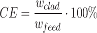 |
3 |
Here, Wclad represents the increase in substrate weight after cladding process, and Wfeed is the weight of input powder, determined by the product of powder feed rate and cladding duration.
For the cladding efficiency, the Signal-to-Noise Ratio (SNR) conversion criterion is based on the “larger-the-better” (LTB) approach. The formula for this criterion is:
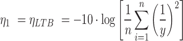 |
4 |
In this equation,  represents the Signal-to-Noise Ratio (SNR) for cladding efficiency, y1 denotes the measurement value from the i-th experiment, and n indicates the number of experiment repetitions.
-
(b)
Porosity (Pt).
After depositions process, the specimens were sectioned along their cross-sections using Wire Electrical Discharge Machining (WEDM). The specimens were then ground and polished using sandpaper and diamond slurry. Images of the cross-sections were captured using a Leica DM6000M optical microscope at 7.5 magnification times, and the area of the pores was calculated using the image software ImageJ. Example images as illustrated in Fig. 314 are used to explain the definition of porosity, where the white areas represent the deposited workpiece, and the black areas indicate the pores. Figure 3a,c exhibit a small amount of porosity, whereas Fig. 3b,d contain a significant amount of porosity.
Fig. 3.

An image of specimen cross-section.
The porosity (Pt) is calculated using the following formula:
 |
5 |
Where  is the sum of cross-sectional areas of the pores,
  denotes the cross-sectional area of deposited material, and
  stands for the cross-sectional area of the melt pool.
The Smaller-the-better (STB) criterion applies when converting product quality into the signal-to-noise ratio (SNR) without a fixed setting or expected value, focusing instead on achieving smaller numerical values. Moreover, the measurement values of this quality must be positive, allowing the target value m to be considered as 0. In the calculation of porosity, the aim is to minimize the presence of pores in the deposited area. The corresponding formula is:
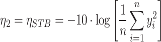 |
6 |
In this case,  represents the Signal-to-Noise Ratio (SNR) for porosity.
-
(c)
Deposition rate (DR)2.
Cladding efficiency is an indicator for optimizing material costs, while the deposition rate (DR) is used to optimize time efficiency. In this study, Jun-Ru Qiu’s research2 was referenced, where the deposition rate is defined as the weight of powder deposited onto the substrate per unit of time.
The formula for calculating deposition rate is as follows2:
 |
7 |
Here, DR is expressed in grams per minute (g/min), Wclad is the increase in substrate weight after cladding, and t is the processing time in seconds.
Grey relational analysis18
The Taguchi method is effective for optimizing a single quality characteristic and identifying the best factor settings. However, the Directed Energy Deposition (DED) optimization problem addressed in this research involves multiple quality characteristics. To simultaneously account for all quality characteristics without bias, this study employed Grey Relational Analysis (GRA) based on the Taguchi experimental design to identify the optimal factor settings. The GRA process consists of three steps:
Grey relation generating.
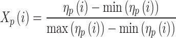
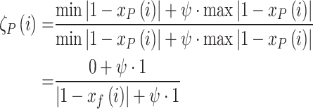
Grey relational generation refers to the process of converting data of different scales into comparable forms. Considering the characteristics of Signal-to-Noise Ratios (SNR), the SNRs of the three quality characteristics were normalized to a [0,1] range. The normalization formula is shown in (8).
 |
8 |
Here,  represents the Signal-to-Noise Ratio (SNR) of the P-th quality characteristic for the i-th experimental group in the Taguchi experiment. P denotes different quality characteristics, and i refer to the experimental group within the L9 orthogonal array.
  represents the normalized SNR.
-
(b)
Grey relational coefficient (GRC) calculation.
Next, the normalized SNR values were converted into Grey Relational Coefficients (GRC). The formula for calculating the GRC is:
 |
9 |
Where  represents the Generative Rate Coefficient (GRC) of the P-th quality characteristic for the i-th experimental group.
  is the distinguishing coefficient, which can range from 0 to 1, with a typical value of 0.5.
-
(c)
Grey relational grade (GRG) calculation.
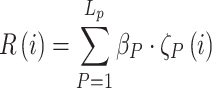
Finally, the three GRCs were combined to calculate the Grey Relational Grade (GRG) using equal weight values. The formula for GRG calculation is:
 |
10 |
Here  represents the Generative Taye Group (GRG) of the i-th experimental group in the L9 Taguchi experiments, which is determined by combining the Generative Rate Coefficients (GRC) of three different qualities characteristics, as shown in Fig. 4.
  denotes the weight assigned to the P-th quality characteristic, and in this study, it is uniformly set to 1/3 for all qualities characteristics.
Fig. 4.

GRA procedure diagram.
By following these three steps, the three SNR values were integrated into a single GRG. Subsequently, the Taguchi method was used to analyze the control factors and determine the optimal factor settings.
Results and discussion
75%SS316L-IN718
The deposition product of 75% SS316L-25% IN718 is shown in Fig. 5. The results of the Taguchi experiments and the transformed Grey Relational Grade (GRG) are presented in the table below:
Fig. 5.

The deposition product of 75% SS316L-25%IN718.
After calculating the GRG, the study followed Taguchi’s method again to make a factor response graph to analyze the effects of control factors on the variation of GRG.
The core of grey relational analysis is used to quantify the degree of correlation between different response variables. When the performance of a single control factor is closely related to other control factors, the GRG value increases, indicating that the experimental condition performs well across multiple responses and is closer to ideal overall performance. Conversely, if the correlation between response variables weakens and the GRG value decreases, that condition no longer optimizes overall performance. As shown in Fig. 6, factor B exhibits a lower GRG value under the B1 setting, indicating that the B1 control factor setting does not contribute positively to the experiment. In contrast, the B3 setting shows a significantly higher GRG value, suggesting that the B3 control factor performs well in the experiment.
Fig. 6.

Response graph of GRG(R).
Figure 6; Table 7 shows that an increase in scanning speed (C) and overlap (D) leads to a decrease in the Level value. This is due to the shortened deposition time reducing heat accumulation, which easily forms pores, and the high overlap causing excessive local energy density, resulting in material vaporization and the formation of pores8. Conversely, an increase in powder feed rate (A) and laser power (B) raises the Level value. A higher powder feed rate reduces energy density, preventing the formation of keyholes, while increased laser power effectively melts the powder, extending solidification time, allowing bubbles more time to escape, and reducing porosity22.
Table 7.
The GRG obtained at the condition of F factor and K level.
| GRG | A | B | C | D |
|---|---|---|---|---|
| Powder feed rate | Laser power | Scanning speed | Overlap ratio | |
| Level 1 | 0.521 | 0.425 | 0.555 | 0.679 |
| Level 2 | 0.567 | 0.555 | 0.645 | 0.625 |
| Level 3 | 0.614 | 0.722 | 0.502 | 0.398 |
| Range | 0.093 | 0.297 | 0.142 | 0.280 |
According to Table 7; Fig. 6,the impact of each factor on the variation of Grey Relational Grade (R) follows this sequence: laser power (B) > overlap ratio (D) > scanning speed (C) > powder feed rate (A). The optimal factor combination that yields the highest R value is identified as A3B3C2D1, where the powder feed rate is 1.2 rpm, laser power is 1700 W, scanning speed is 9 mm/s, and the overlap ratio is 30%. The subsequent Chap. 4 will include one-factor-at-a-time experiments to verify the correctness of the optimization results.
50%SS316L-50%IN718
The deposition product of 50% SS316L-50% IN718 is shown in Fig. 7. The results of the Taguchi experiments and the transformed Grey Relational Grade (GRG) are presented in the table below:
Fig. 7.

The deposition product of 50% SS316L-50%IN718.
After calculating the GRG, the study followed Taguchi’s method again to make a factor response graph to analyze the effects of control factors on the variation of GRG.
According to Table 8; Fig. 8, the impact of each factor on the variation of Grey Relational Grade (R) follows this sequence: laser power (B) > overlap ratio(D) > scanning speed (C) > powder feed rate (A). The optimal factor combination that yields the highest R value is identified as A3B3C2D1, where the powder feed rate is 1.2 rpm, laser power is 1700 W, scanning speed is 9 mm/s, and the overlap ratio is 30%.
Table 8.
The GRG obtained at the condition of F factor and K level.
| GRG | A | B | C | D |
|---|---|---|---|---|
| Powder feed rate | Laser power | Scanning speed | Overlap ratio | |
| Level 1 | 0.544 | 0.402 | 0.511 | 0.683 |
| Level 2 | 0.564 | 0.568 | 0.638 | 0.588 |
| Level 3 | 0.571 | 0.708 | 0.530 | 0.408 |
| Range | 0.027 | 0.306 | 0.127 | 0.275 |
Fig. 8.

Response graph of GRG(R).
25%SS316L-75%IN718
The deposition product of 25% SS316L-75% IN718 is shown in Fig. 9. The results of the Taguchi experiments and the transformed Grey Relational Grade (GRG) are presented in the table below:
Fig. 9.

The deposition product of 25% SS316L-75% IN718.
After calculating the GRG, the study followed Taguchi’s method again to make a factor response graph to analyze the effects of control factors on the variation of GRG.
According to Table 9; Fig. 10, the impact of each factor on the variation of Grey Relational Grade (R) follows this sequence: laser power (B) > overlap ratio(D) > scanning speed (C) > powder feed rate (A). The optimal factor combination that yields the highest R value is identified as A3B3C2D1, where the powder feed rate is 1.2 rpm, laser power is 1700 W, scanning speed is 9 mm/s, and the overlap ratio is 30%.
Table 9.
The GRG obtained at the condition of F factor and K level.
| GRG | A | B | C | D |
|---|---|---|---|---|
| Powder feed rate | Laser power | Scanning speed | Overlap ratio | |
| Level 1 | 0.621 | 0.452 | 0.576 | 0.657 |
| Level 2 | 0.573 | 0.612 | 0.651 | 0.598 |
| Level 3 | 0.630 | 0.760 | 0.597 | 0.568 |
| Range | 0.057 | 0.308 | 0.074 | 0.089 |
Fig. 10.

Response graph of GRG(R).
Verification and one-factor-at-a-time experiments
One-factor-at-a-time experiment results
This study found an optimal factor setting A3B3C2D1 for a multi-layer and multi-track DED process that can take three qualities into account. However, optimization results are limited to selecting the optimal combination of factor levels. For example, when we choose laser power as the control factor for Taguchi experiments, the results may show that among the levels 900 W, 1300 W, and 1700 W, 1700 W performs the best. This approach cannot inform us about the existence of other levels, such as 1500 W.
According to the study by Kuriya et al.22, the accumulation of heat prolongs the solidification time of both the deposited material and the melt pool, allowing for bubble escape and thereby reducing product porosity. However, with a higher overlap ratio, although the reduced distance between tracks keeps the previous deposition layer under continued thermal influence from new layers—facilitating bubble release—excessive heat accumulation may result in structural deformation or increased defects, ultimately reducing quality. Meanwhile, the increasing in overlap ratio shortens the distance between adjacent tracks, enhancing the likelihood of powder impacting the previously deposited material and rebounding, and thus increases surface roughness of the part which is not welcome in 3D printing industry24.
To optimize outcomes, overlap ratios of 20% and 30% were selected for single-factor (OFAT) experiments to mitigate excessive thermal effects while preserving sufficient bubble escape opportunities. This approach enables a more detailed analysis of individual factors, ultimately identifying truly optimal process parameters for ideal results.
Considering the Grey Relational Grade (GRG) results for each proportion from Chap. 4 (comprising three quality aspects), this study fine-tuned the two control factors that have the most significant impact on the variation of GRG. The remaining control factors were kept at the optimal combination indicated by the grey relational analysis. Based on this foundation, OFAT experiments were conducted, involving the deposition of the same three-dimensional rectangle as in the Taguchi experiments. The aim was to observe trends in product quality changes. By adjusting the significant factors after fine-tuning, a more optimal combination of process parameters was found.
Building upon the optimization results of Taguchi experiments for each proportion, the results of fine-tuning significant factors through OFAT experiments are presented in the table below. In this table, Run 10 for each proportion are repetitions of the optimization results from Chap. 3. Runs 11 to 13 sequentially adjust the significant factors to validate the repeatability of the Taguchi experiments and further optimize the process parameters.
Table 10 presents the results of the one-factor-at-a-time (OFAT) experiments with variations in laser power and overlap ratio based on the optimal factor combination A3B3C2D1. The results showed that for the two mixing ratios, 75% SS316L-25% IN718 and 50% SS316L-50% IN718, the optimal process parameters were laser power of 1900 W and overlap ratio of 30%. However, when the content of SS316L is reduced to 25%, specifically in the case of 25% SS316L-75% IN718, the optimal result can be achieved with a laser power of only 1800 W. In contrast, a laser power of 1900 W results in suboptimal cladding efficiency and deposition rate due to excessive energy deposition. Therefore, the subsequent tensile testing experiments in this section were conducted based on the optimization results from this subsection.
Table 10.
Results of OFAT experiment.
| Run | A | B | C | D | Cladding efficiency (%) | Porosity (%) | Deposition rate (g/min) | Grey relation grade(R) |
|---|---|---|---|---|---|---|---|---|
| Powder feed rate (rpm) | Laser power (W) | Scanning speed (min/s) | Overlap ratio (%) | |||||
| 75%SS316L-25%IN718 | ||||||||
| A10 | 1.2 | 1700 | 9 | 30 | 37.50% | 0.1375% | 4.43 | 0.374 |
| A11 | 1700 | 20 | 41.46% | 0.1512% | 4.90 | 0.586 | ||
| A12 | 1800 | 30 | 41.16% | 0.1511% | 4.86 | 0.550 | ||
| A13 | 1900 | 30 | 42.53% | 0.1194% | 5.02 | 1.000 | ||
| 50%SS316L-50%IN718 | ||||||||
| B10 | 1.2 | 1700 | 9 | 30 | 52.02% | 0.0910% | 6.19 | 0.679 |
| B11 | 1700 | 20 | 36.29% | 0.0790% | 4.32 | 0.357 | ||
| B12 | 1800 | 30 | 50.81% | 0.0748% | 6.05 | 0.662 | ||
| B13 | 1900 | 30 | 53.83% | 0.0527% | 6.41 | 1.000 | ||
| 25%SS316L-75%IN718 | ||||||||
| C10 | 1.2 | 1700 | 9 | 30 | 34.20% | 0.1194% | 4.10 | 0.346 |
| C11 | 1700 | 20 | 39.60% | 0.0699% | 4.75 | 0.544 | ||
| C12 | 1800 | 30 | 43.80% | 0.1460% | 5.26 | 0.778 | ||
| C13 | 1900 | 30 | 36.00% | 0.0388% | 4.32 | 0.591 | ||
Microstructure analysis
In recent years, the rapid development of composite material manufacturing processes has highlighted the importance of inter-material bonding as a key factor in improving process performance. The microstructure of materials significantly influences product quality. This study employs a corrosion method to observe the microstructure of composite materials, providing a reference standard for future composite material processing to accurately assess product quality.
Aqua regia was selected as the etchant in this study, with a volumetric ratio of 1:3 for nitric acid and hydrochloric acid (HNO₃ + 3HCl). The etching method involved immersing the specimens in the etchant for approximately 5 s, followed by thorough rinsing with deionized water and finally wiping the specimen surface with alcohol to remove any residual etchant.
The microstructural observations were conducted using a KEYENCE VHX-7000 optical microscope at a magnification of 200x. Specimens prepared with various etching ratios were observed, and their microstructural features were recorded. This paper analyzes the experimental results of three different etchant ratio combinations to investigate the effect of varying etching ratios on the phase structure.
Figure 11 shows that when the composition ratio is 75% SS316L and 25% IN718, the internal grain structure of the sample primarily consists of equiaxed grains, with small cracks observed within the finer equiaxed grains. These cracks are closely associated with uneven internal stress distribution and increased porosity under specific processing conditions. The presence of a distinctly oriented needle-like structure and numerous discrete grain boundaries within this microstructure affects the material’s mechanical properties and deformation behavior, serving as initiation points for cracks. Additionally, the higher SS316L content, with its FCC lattice structure, promotes plastic deformation; however, lacking the reinforcement from IN718, it struggles to prevent stress concentration and cracking. The discontinuous distribution of the IN718 phase creates localized weak regions and combined with mismatches in thermal expansion and lattice structure differences, this further intensifies brittleness and the propagation of microcracks19,23,25.
Fig. 11.

Microstructure result of 75%SS316L-25%IN718.
According to the research by M.S. Duval-Chaneac et al.19, these cracks likely form due to differences in the solidification rates of the two materials during the cooling process, leading to thermal stress-induced cracking. The presence of finer equiaxial grains typically occurs at higher cooling rates, which indirectly confirms that variations in internal cooling rates contributed to crack formation.
Figures 12 and 13 illustrate the microstructures of samples with 50% SS316L-50% IN718 and 25% SS316L-75% IN718 ratios. As the IN718 content increases, the proportion of columnar grains gradually rises, and the needle-like structures exhibit a certain directionality. No fine equiaxed grains indicative of rapid cooling was detected in these microstructures, aligning with the findings of Beytullah Aydogan et al.11, who reported that as the proportion of nickel-based (Ni) material increases, the thermal conductivity of the material decreases, thereby reducing the likelihood of crack formation due to thermal stress.
Fig. 12.

Microstructure result of 50%SS316L-50%IN718.
Fig. 13.

Microstructure result of 25%SS316L-75%IN718.
Additionally, no visible cracks were observed in the 50% SS316L-50% IN718 and 25% SS316L-75% IN718 samples. This can be attributed to their stable microstructure and uniform deformation behavior during processing. In the 50% SS316L-50% IN718 composite, the balanced ratio between the FCC structure of SS316L and the complex lattice of IN718 promotes uniform stress distribution, reducing internal stress concentration and enhancing crack resistance, allowing the material to remain stable even under significant deformation. In the 25% SS316L-75% IN718 composition, the high IN718 content provides exceptional strength and resistance to dislocation movement, ensuring even tensile stress distribution and reducing the likelihood of crack formation. The small proportion of SS316L serves as a stabilizing phase that aids in stress absorption and dissipation, forming a robust microstructure capable of withstanding high loads without developing defects11. These findings align with the observations in Sect. 4.1, underscoring the critical role of stable microstructures and uniform stress distribution in enhancing the mechanical integrity of these composites.
Tensile test experiments
Having identified the optimal process parameters for each proportion in this study, this section involved the deposition of finished products for the three ratios, followed by conducting tensile testing. Additionally, to prevent the occurrence of unnecessary cracks due to thermal stress within the material, no heat treatment was carried out. The experimental equipment employed was the Micro-Tensile-Compression-Tester DDS2, as depicted in Fig. 14. For the DED thin-wall products, they were processed into tensile specimens through wire cutting and grinding machine. The image and dimensions of the specimens are illustrated in Fig. 15. The fabrication parameters for the tensile specimens of each ratio are provided in Table 11.
Fig. 14.

Micro-Tensile-Compression-Tester DDS2.
Fig. 15.

(a) Image and (b) dimensions of tensile test samples. (Thickness: 1.5 mm)
Table 11.
The process parameters of tensile test samples.
| Powder feed rate (rpm) | Laser power (W) | Scanning speed (mm/s) | Overlap ratio(%) | |
|---|---|---|---|---|
| 75%SS316L-25%IN718 | 1.2 | 1900 | 9 | 30 |
| 50%SS316L-50%IN718 | 1.2 | 1900 | 9 | 30 |
| 25%SS316L-75%IN718 | 1.2 | 1900 | 9 | 30 |
Table 12, based on the one-factor-at-a-time experiment from Table 11, sliding levels were considered in the Taguchi experiments to identify the optimal deposition process parameters for different material ratios. The tensile tests of 50% SS316L-50% IN718 and 25% SS316L-75% IN718 (as shown in Fig. 16) revealed similar Ultimate Tensile Strength (UTS) results. However, both exceeded the UTS of the 75% SS316L-25% IN718 composition. This difference is primarily attributed to the higher IN718 content, which influences the mechanical properties, resulting in a lower UTS for the latter composition. The SS316L matrix, with its greater ductility, deforms more easily under tensile stress, causing earlier failure. These findings correspond with the results outlined in Sect. 4.2.
Table 12.
Tensile test result.
| Powder feed rate (rpm) | Laser power (W) | Scanning speed (mm/s) | Overlap ratio (%) | Ultimate Tensile Strength | Elongation | |
|---|---|---|---|---|---|---|
| 75%SS316L-25%IN718 | 1.2 | 1900 | 9 | 30 | 274.15 Mpa | 4.92% |
| 50%SS316L-50%IN718 | 1.2 | 1900 | 9 | 30 | 464.147 Mpa | 13.53% |
| 25%SS316L-75%IN718 | 1.2 | 1800 | 9 | 30 | 499.37 Mpa | 10.34% |
Fig. 16.

Tensile test result.
Moreover, phase distribution and the occurrence of grain boundary sliding or void formation may also contribute to the reduction in UTS. When the proportion of IN718 is lower, its phase distribution within the material may become discontinuous, forming isolated strong-phase regions. This increases the likelihood of grain boundary sliding or void formation, causing uneven strength distribution and, consequently, lower tensile strength.
Additionally, the phase distribution problem is significant, as evidenced by elongation data. The discontinuous distribution of IN718 in the 75%SS316L-25%IN718 composite limits plastic deformation, resulting in very low elongation values. The low IN718 content not only fails to enhance the material’s inherent high strength and hardness but also suppresses SS316L’s high ductility due to grain boundary sliding and void formation19.
Based on the tensile testing results depicted in Fig. 16, it was observed that when the IN718 content was 25% and 50%, the tensile curves exhibited erratic behavior. This phenomenon can be attributed to the presence of cracks within the specimens, leading to internal stress concentration and eventual fracture. According to Wen’s research, higher IN718 content results in a gradual increase in the material’s ultimate tensile strength (UTS) while elongation decreases27. This observation aligns with the findings of this study. Furthermore, specimens with IN718 contents of 25% and 75% displayed brittle fractures, likely due to poor bonding between the materials resulting from the interactions of the alloy composition and structure. In high-temperature IN718 alloys, the formation of MC carbides (such as NbC) depletes carbon in the interdendritic melt, allowing other alloying elements to remain concentrated. Simultaneously, the presence of Laves phases around these carbides can adversely affect the microstructure and properties of the alloy.
In SS316 stainless steel, the presence of carbides (such as M23C6) can also deplete carbon in the matrix, potentially promoting grain boundary embrittlement. Moreover, the formation of other secondary phases can adversely affect the microstructure, reducing mechanical properties and corrosion resistance. The presence of these secondary phases may also induce localized corrosion phenomena, diminishing the alloy’s reliability in harsh environments23.
According to the summarized tensile testing results (Table 12), it was found that the specimen with a composition of 25% SS316L-75% IN718 exhibited the highest maximum tensile strength, reaching 499.37 MPa. In terms of elongation, the specimen with a composition of 50% SS316L-50% IN718 demonstrated the best performance, achieving an elongation of 13.53%. As a result, the cracks observed in Fig. 11 of Sect. 4.2 are attributed to the presence of numerous secondary phases in the 75% SS316L-25% IN718 mixture, which significantly increases brittleness26,27. Additionally, issues such as uneven internal stress distribution and thermal expansion mismatch contribute to crack formation. In contrast, the increased proportion of nickel-based materials in Figs. 12 and 13 reduces thermal stress within the composite, thereby minimizing cracks caused by thermal expansion and achieving a balance between strength and flexibility.
In summary, based on data analysis, the alloy with 25% SS316L content exhibited the best performance in terms of tensile strength. While the alloy with 50% SS316L content fell short in terms of tensile strength compared to the 25% composition, it demonstrated superior elongation. These findings provide valuable insights for further evaluation and application of the performance characteristics of these alloys.
Conclusion
This study conducted deposition experiments on three different mixing ratios using the Taguchi L9 orthogonal array with four factors and three levels, analyzing the impact of these ratios on product quality and performance. The main conclusions of this study are as follows:
Composite materials with different mixing ratios exhibit varying effects on the same process parameters, indicating the need for different optimal process parameters for materials with different mixing ratios.
It was observed that a too low Ni content, under high laser power, leads to the generation of cracks. This is attributed to the correlation between Ni content and the material’s thermal conductivity, making it susceptible to thermal stress.
The study analyzed the tensile test results, revealing that samples with different mixing ratios exhibit varying tensile performances when using optimized parameters. For instance, the sample with a mixing ratio of 25% SS316L-75% IN718 demonstrated the highest ultimate tensile strength, reaching 499.37 MPa. However, in terms of elongation, the sample with a mixing ratio of 50% SS316L-50% IN718 performed the best, achieving an elongation of 13.53%.
The mechanical performance of the composite material is adversely affected by the high proportion of IN718, which decreases the ultimate tensile strength (UTS). While SS316L, as the matrix, offers greater ductility, its susceptibility to deformation can lead to premature failure. Additionally, the discontinuous phase distribution of IN718 at lower proportions creates isolated strong regions, increasing the likelihood of grain boundary sliding and void formation, resulting in uneven strength distribution. This phenomenon is reflected in the elongation data, where the limited plastic deformation in the 75% SS316L-25% IN718 composite yields very low elongation values. Thus, a lower IN718 content not only fails to enhance the material’s strength and hardness but also diminishes the ductility of SS316L.
In summary, the study emphasizes a significant correlation between mixing material ratios and process parameters, particularly in terms of tensile performance and crack formation.
Author contributions
Y.X. Chen and J. R. Qiu were primarily responsible for conducting the overall experiment, while W. L. Chang and Y. K. Hwang assisted with writing the manuscript. All authors reviewed the manuscript.
Funding
The authors declare that no funds, grants, and other support were received during the preparation of this manuscript.
Data availability
Data is provided within the manuscript information files.
Declarations
Competing interests
The authors declare no competing interests.
Ethics approval
The authors confirm the novelty of the reported work and confirm that it is not submitted to any other journal.
Consent for participate
The authors give consent to participate.
Consent for publication
The authors give consent for publication.
Footnotes
Publisher’s note
Springer Nature remains neutral with regard to jurisdictional claims in published maps and institutional affiliations.
References
- 1.International, A. S. T. M. ISO/ASTM52900-15 Standard Terminology for Additive Manufacturing-General Principles-Terminology (ASTM International, 2015).
- 2.Qiu, J. R. Directed energy deposition process optimization and factors interaction analysis by response surface methodology, Master Thesis, Department of Mechanical Engineering, National Cheng Kung University, (2022).
- 3.Nathan, A. et al. Effect of Processing conditions on the microstructure, porosity, and mechanical properties of Ti-6Al-4V Repair fabricated by directed energy deposition. J. Mater. Process. Technol.264, 172–181 (2019). [Google Scholar]
- 4.Zhong, C. L., Biermann, T., Gasser, A. & Poprawe, R. Experimental study of effects of main process parameters on porosity, track geometry, deposition rate, and powder efficiency for high deposition rate laser metal deposition. J. Laser Appl.27, 042003 (2015). [Google Scholar]
- 5.Makoto Fujishima, Y., Oda, R., Ashida, K., Takezawa & Kondo, M. Study on factors for pores and cladding shape in the deposition processes of Inconel 625 by the directed energy deposition (DED) method CIRP J. Manuf. Sci. Technol.19, 200–204 (2017). [Google Scholar]
- 6.Anam, Asghar & Abdul Aziz Abdul Raman, and Wan Mohd Ashri Wan Daud. A comparison of central composite design and taguchi method for optimizing fenton process. Sci. World J.10.1155/2014/869120 (2014). [DOI] [PMC free article] [PubMed] [Google Scholar]
- 7.Ng, G. K. L., Jarfors, A. E. W., Bi, G. & Zheng, H. Y. Porosity formation and gas bubble retention in laser metal deposition. Appl. Phys. A97, 641–649 (2009). [Google Scholar]
- 8.Zheng, B. et al. On the evolution of microstructure and defect control in 316L SS components fabricated via directed energy deposition. Mater. Sci. Eng. A764, 138243 (2019). [Google Scholar]
- 9.Guo, C., He, S., Yue, H., Li, Q. & Hao, G. Prediction modelling and process optimization for forming multi-layer cladding structures with laser directed energy deposition. Opt. Laser Technol.134, 106607 (2021). [Google Scholar]
- 10.Mohammad Ansari, A., Mohamadizadeh, Y., Huang, V., Paserin & Toyserkani, E. Laser directed energy deposition of water-atomized iron powder: Process optimization and microstructure of single-tracks. Opt. Laser Technol.112, 485–493 (2019). [Google Scholar]
- 11.Beytullah Aydogan & Sahasrabudhe, H. Enabling multi-material structures of Co-based superalloy using laser directed energy deposition additive manufacturing. Metals11, 1717 (2021). [Google Scholar]
- 12.Daniel Melzer, J., Dˇzugan, M., Koukolíkov´a, S., Rzepa & Vavˇrík, J. Structural integrity and mechanical properties of the functionally graded material based on 316L/IN718 processed by DED Technology. Mater. Sci. Eng. A811, 141038 (2021). [Google Scholar]
- 13.Chao Wei, L. et al. Multi-material additive manufacturing of tungsten copper alloy bimetallic structure with a stainless-steel interlayer and associated bonding mechanisms. Additive Manuf.50, 102574 (2022). [Google Scholar]
- 14.Sweet, G. A. W. et al. Laser-based directed energy deposition (L-DED) processing of water atomized 42CrMo4 powder. Lasers Manuf. Mater. Process.10, 32–63 (2023). [Google Scholar]
- 15.Wu, T. M. A Study of activating flux to the welding penetration of nickel base superalloy Inconel 718, Master Thesis, Degree Program of Automation and Precision Engineering, National Chiao Tung University, (2009).
- 16.Daniel, H. & Herring the heat treatment of Inconel® 718. (2019). https://www.industrialheating.com/articles/94990-the-heat-treatment-of-inconel-718
- 17.Hui-Huang Li Taguchi Methods: Principles and Practice of Quality Design. Gao Li Publishing Company, Taiwan, (2011).
- 18.Wen, K. L., Chang-Chiem, S. K. & Yeh, C. K. Chien-Wen Wang and Hui-Shan Lin Application of MATLAB in Grey System Theory (Chuan Hwa Book Company, 2006).
- 19.Duval-Chaneac, M. S. et al. Fatigue Crack Growth in IN718/316L multi-materials layered structures fabricated by laser powder Bed Fusion. Int. J. Fatigue. 152, 106454 (2021). [Google Scholar]
- 20.Pan, L. K., Wang, C. C., Wei, S. L. & Sher, H. F. Optimizing multiple quality characteristics via Taguchi method-based grey analysis. J. Mater. Process. Technol.182, 107–116 (2007). [Google Scholar]
- 21.Li, Y. X. & Ma, J. Study on overlapping in the laser cladding process. Surf. Coat. Technol.90, 1–5 (1997). [Google Scholar]
- 22.Tatsuhiko Kuriya, R., Koike, T., Mori, Y. & Kakinuma relationship between solidification time and porosity with directed energy deposition of Inconel 718. J. Adv. Mech. Des. Syst. Manuf.12, 104–114 (2018). [Google Scholar]
- 23.Ghanavati, R., Naffakh-Moosavy, H. & Moradi, M. Additive manufacturing of thin-walled SS316L-IN718 functionally graded materials by direct laser metal deposition. J. Mater. Res. Technol.15, 2673–2685 (2021). [Google Scholar]
- 24.Lin, P. Y., Shen, F. C., Wu, K. T., Hwang, S. J. & Lee, H. H. Process optimization for directed energy deposition of SS316L components. Int. J. Adv. Manuf. Technol.111, 1387–1400 (2020). [Google Scholar]
- 25.Ramkumar, T. et al. Studies on the structural property, mechanical relationships and corrosion behaviors of Inconel718 and SS316L dissimilar joints by TIG welding without using activated flux. J. Manuf. Process.30, 290–298 (2017). [Google Scholar]
- 26.Ghanavati, R., Naffakh-Moosavr, H., Moradi, M. & Eshraghi, M. Printability and microstructure of directed energy deposited SS316L-IN718 multi-material: Numerical modeling and experimental analysis. Sci. Rep.12 (1), 16600 (2022). [DOI] [PMC free article] [PubMed] [Google Scholar]
- 27.Wen, Y. et al. Microstructure-property correlations in as-built and heat-treated compositionally graded stainless steel 316L-Inconel718 Alloy fabricated by laser powder bed fusion. Mater. Sci. Eng. A862, 144515 (2023). [Google Scholar]
Associated Data
This section collects any data citations, data availability statements, or supplementary materials included in this article.
Data Availability Statement
Data is provided within the manuscript information files.