Abstract
This paper exhibits a proportional-type robust current controller for permanent magnet synchronous motors (PMSMs), incorporating the variable bandwidth technique driven by the proposed online auto-tuner and the disturbance observer (DOB) as the subsystems. There are two contributions: (a) the proposed online auto-tuner implements the variable bandwidth for the closed-loop system to boost the transient current tracking performance and (b) the combination of proportional-type feedback controller and DOB eliminates the requirement of the integral action, ensuring the steady-state error rejection property. Moreover, it is proved that the resultant feedback system recovers the target current tracking performance without steady-state errors. The experimental study is conducted to verify the efficacy of the proposed controller using a 700-W prototype PMSM.
Keywords: Permanent magnet synchronous motors, Current control, Auto-tuner, Disturbance observer, Parameter uncertainty
Subject terms: Electrical and electronic engineering, Applied mathematics
Introduction
The permanent magnet synchronous motor (PMSM) has been considered a promising solution to induction motors (IMs) and DC motors due to their high efficiency and simple structure. These advantages have widened their applications such as tension controls, electric power steering (EPS), home appliances, electric vehicles, and so on1–5.
The torque control is essential for speed and position control system, which can be implemented by the classical direct torque control (DTC) technique. Recently, the rotational coordinate transform based current control scheme has been adopted for the torque control due to its high performance and low current ripple, which is called the vector control technique. In the resulting rotational d-q frame, a simple proportional–integral (PI) regulator has been used to regulate the d-q frame current errors. Their PI gains were tuned through a trial-and-error process and frequency domain analysis technique, called the Bode and Nyquist methods6,7, for a fixed operating point. For wide-range operating range, an extra online gain selector has to be embedded in the control algorithm8. To overcome this limitation, the feedback-linearization (FL) method was applied, which is composed of the PI regulator and a feed-forward compensation for the disturbance from the back EMF effect9–11. The PMSM parameter dependent PI gains and feed-forward compensator force the closed-loop dynamics to be a low-pass filter (LPF) with a desired bandwidth via a pole-zero cancellation. To guarantee the desired closed-loop performance, the on-line or off-line parameter identification (ID) algorithms must be combined with the FL controller12–15. The parameter dependency problem can be alleviated by the sliding mode control method in Ref.16. This scheme requires a conservative lower and upper bounds of the PMSM parameters for the discontinuous sign-function gain and feed-forward compensator, which could produce an excessive control signal. A novel model predictive control (MPC) technique was proposed with a significant reduced computational complexity, compared with classical MPC methods17,18. The closed-loop optimality and control input feasibility can be guaranteed with additional ID algorithms like to the FL controller. It was reported that the disturbance observe (DOB) can be used as an effective solution to construct the feed-forward compensator while eliminating the steady-state errors19,20. Recently, the DOB based current controller was systematically developed for PMSMs with a rigorous closed-loop stability and property analysis21. These surveyed techniques assign the fixed bandwidth to the closed-loop system by their well-tuned control gains. The magnified control gains could improve the transient performance but result in an efficiency degradation in steady-state operations.
Unlike the literature mentioned above, this study devises a novel variable bandwidth-based proportional-type current controller subject to the constraints;
(C1) an fixed a high-level of current feedback gain to ensure the desired outer loop bandwidth for speed and position loops;
(C2) the requirement of the integral actions for the control loop involving the additional anti-windup mechanisms to ensure the steady-state error rejection;
(C3) the true PMSM parameter dependence of the controller to secure the desired closed-loop stability and performance.
The proposed technique considering these constraints makes the following major contributions:
The proposed auto-tuner continuously updates the feedback gain according to the simple rule in the analytic form to find the desired closed-loop bandwidth for the transient and steady-state operations, resulting in improved current tracking performance and lowered current ripple level (for (C1)).
The proportional-type current controller employs the reduced-order DOB as a subsystem as a replacement of the integrator to simplify the resultant feedback system structure by removing the requirement of the additional anti-windup mechanisms, so that it ensures the performance recovery property (for (C2) and (C3)).
Moreover, practical advantages are shown by providing convincing experimental data using a 700-W prototype PMSM dynamo system.
Current and speed dynamics of PMSMs
In accordance with result9, the PMSM current dynamics are described in the rotational d-q frame as
| 1 |
| 2 |
where , , , denote the current (in A) and voltage (in V) represented in the rational d-q frame, respectively. The electrical speed is defined as with P and being the pole-pair numbers and rotor speed in rad/s, which is used to transform the reference frame into the rational d-q frame. The inductance values in this frame are given as , , (in H) and the stator resistance and flux are represented as (in ) and (in Wb), respectively.
The PMSM mechanical speed dynamics is related to the d-q frame current as
| 3 |
with the load torque and electrical torque defined as
where J and B represent the inertia and viscous damping constants, respectively, and . Note that the PMSM speed acts as the internal dynamics in the current control mode. Fortunately, it is proved that any stabilizing current controller stabilizes the internal dynamics coming from the PMSM speed. See21 for details. Thus, this study focuses on developing the current tracking controller without internal dynamics analysis.
The next section designs an advanced current control algorithm under the practical assumptions:
(A1) The nominal PMSM parameter values, , , , , are available, but their variations are unknown. e.g., , , and with unknown variations , , and .
(A2) The d-q frame current , , and mechanical speed are available for feedback using the shut resistors and rotary encoder.
Design of proposed proportional-type robust current controller
Control objective
This subsection introduces the variables as and as the Laplace transforms of desired current response and its reference , which defines the transfer function as the base feedback system performance:
| 4 |
with its realization given by
| 5 |
for given desired bandwidth (in rad/s, Hz) determining the current tracking performance and ripple level in the transient and steady-state operations.
To secure both the transient and steady-state behaviors of the feedback system, this work modifies the base desired system (5) such that resulting in the time-varying system
| 6 |
for a variable bandwidth with property , , and initial condition , which is driven by the proposed auto-tuner presented in “Proposed controller” section. This modification constitutes the control objective given by
| 7 |
exponentially (named the performance recovery) to assign variable bandwidth to the resultant feedback system. The controller including the update logic for is designed in “Proposed controller” and “Feedback system analysis results” sections presents the closed-loop system analysis results.
Proposed controller
Open-loop system derivation
Using the notations of (A1) in “Current and speed dynamics of PMSMs” section, the system of (1) and (2) gives an equivalent form given by
| 8 |
| 9 |
with unknown lumped disturbance defined as
which results in the open-loop system for :
| 10 |
where , , , , , and , .
Implementation of proposed controller
This subsection defines the error for given reference , which constructs the proposed current controller to stabilize the open-loop system (10) by the rule given by
| 11 |
where the proposed online auto-tuner drives the time-varying feedback gain along the system given by
| 12 |
involving the design parameters and where (), . The disturbance estimate is governed by the reduced-order DOB:
| 13 |
| 14 |
with the DOB gain . It should be noticed that the reduced DOB of (13) and (14) is derived by referencing the design technique in Ref.20.
The substitution of (11) and (12) to (10) forms the closed-loop current error dynamics as
| 15 |
where , , which is used for “Feedback system analysis results” section to prove the control objective (7) and closed-loop stability. The configuration of resultant feedback system is shown in Fig. 1.
Figure 1.
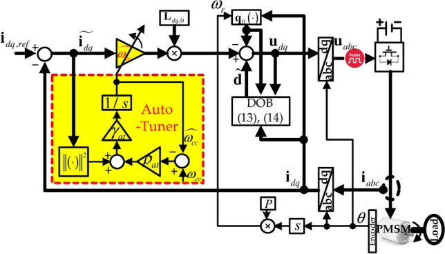
Proposed auto-tuner-based current controller structure.
Feedback system analysis results
This section proves that the proposed solution of (11)–(14) guarantees the control objective (7) and exponential current error convergence through further analysis of the closed-loop dynamics (15) incorporating the subsystem dynamics of (12), (13), and (14). To this end, “Reduced-order DOB analysis results” section begins with the analysis of the reduced-order DOB of (13) and (14).
Reduced-order DOB analysis results
The reduced-order DOB of (13) and (14) does not explicitly show the disturbance estimation tendency for , which is clarified in Lemma 1.
Lemma 1
The reduced-order DOB of (13) and (14) guarantees that
| 16 |
Proof
The time derivative of (14) adopting (13) gives
where the open-loop system (10) showing validates the last equation above; completes the proof.
Remark 1
The result (16) of Lemma 1 derives the system for satisfying
| 17 |
which shows for such that
| 18 |
for any such that ; used for the remaining analysis.
Online auto-tuner analysis results
The proposed online auto-tuner (12) updating the variable bandwidth has a lower bound of its initial bandwidth , which helps to prove the closed-loop properties in Theorems 1 and 2. See Lemma 2 for details.
Lemma 2
The proposed online auto-tuner (12) renders the variable bandwidth to satisfy the inequality
| 19 |
Proof
The system (12) can be written as
whose lower bound can be found by integrating both side:
which verifies the result of this lemma.
Control loop analysis results
This subsection ends the feedback system analysis tasks by proving the design objective (7), exponential current error convergence , and offset-free property using the results (18) and (19) obtained from “Reduced-order DOB analysis results” and “Online auto-tuner analysis results” sections. Theorem 1 begins with the proof of the design objective (7).
Theorem 1
The proposed feedback system shown in Fig. 1 guarantees
exponentially for satisfying
| 20 |
(e.g., accomplishment of the control objective (7)) for any .
Proof
The deviation gives the system along (22) and (20):
which makes with to be
| 21 |
using the results (18) and (19) and fact , , , (Young’s inequality). Then, the selection concludes
where ; completing the proof.
Theorem 2 proves the exponential current error convergence using the result (18) obtained in “Reduced-order DOB analysis results” section. Before proceeding with the formal analysis, rewrite the closed-loop system (15) with the online auto-tuner (12) as
| 22 |
| 23 |
where and , , which is used for a basis to prove the result of Theorem 2
Theorem 2
The proposed feedback system shown in Fig. 1 guarantees
| 24 |
exponentially for any design parameters and of the auto-tuner resulting in .
Proof
The closed-loop trajectories (22) and (23) yield for with as
| 25 |
where the result (18) and Young’s inequality justify the inequality above. Then the selection concludes
| 26 |
where subject to the variable bandwidth (, , by Lemma 2) satisfying ; completing the proof.
The closed-loop system could suffer from a steady-state error because the proposed controller includes the proportional component of current tracking error. However, the reduced-order DOB of (13) and (14) contributes the steady-state error rejection property to the closed-loop system without current tracking error integrators, which is investigated in Theorem 3.
Theorem 3
The proposed feedback system shown in Fig. 1 guarantees
| 27 |
for any steady-state, where and .
Proof
The closed-loop system of (22) and (17) results in the static relationships such that
| 28 |
| 29 |
which completes the proof since the combination of (29) and (28) implies .
Experimental results
This section provides the experimental data to convince the practical merits of the proposed controller and adopts the FL controller for comparison study. The Texas Instruments (TI) DSP28335 implemented the control algorithms under pulse-width modulation (PWM) periods 0.1 ms synchronized to the analog-to-digital conversion and control interrupts. The TI DRV8302-HC-C2-KIT was used as the three-phase inverter with the DC voltage level V. Figure 2 depicts the hardware setup. A 700 W prototype PMSM was used for this experiment where the rated current and speed are 30 A and 3000 rpm, respectively. The PMSM parameters are given by , mH, mH, Wb, , kgm2, Nm/rad/s. It was assumed that the nominal PMSM parameters were given to be not equal to their true values to taking the model-plant mismatches into account, whose values were selected as , , , .
Figure 2.
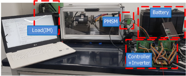
Hardware setup.
For the proposed controller, the bandwidth update algorithm (12) was set to be initiated from its initial bandwidth Hz for rad/s. The rest of design parameters were chosen as , , and . The FL controller (presented in Ref.9) given by
| 30 |
| 31 |
is used for comparison with the bandwidth , which is the same as the initial bandwidth of the proposed controller. Note that the FL controller results in the closed-loop transfer function , , through a pole-zero cancellation, if , , , and , i.e., there are no plant-model mismatches.
Pulse reference tracking test under constant speed load
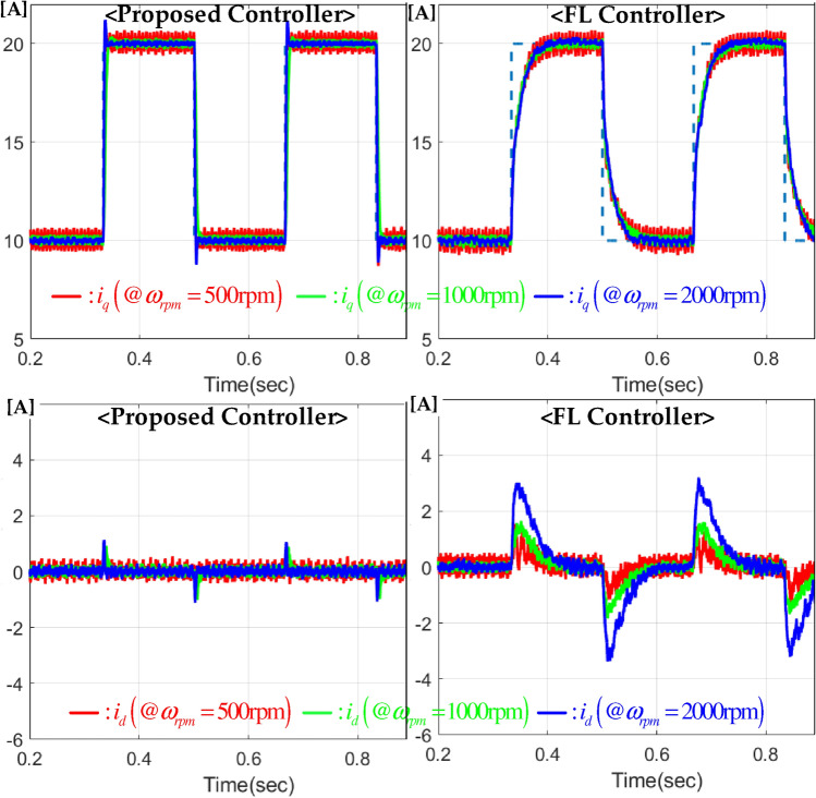
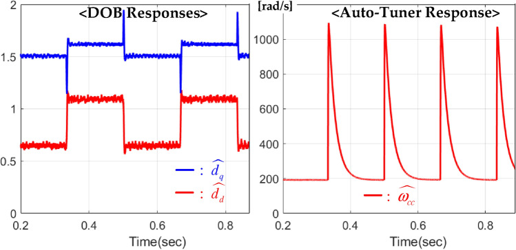
The first experiment verified the q-frame current tracking performance for a pulse-wave reference with . This experiment was repeated for three speed loads of , 1000, and 2000 rpm. The resulting d-q frame current responses are shown in Fig. 3, which observes that the proposed technique considerably enhances the robustness of the feedback system by effectively attenuating the performance degradation from model-plant mismatches and operating mode changes due to the improved feedback system structure including the online auto-tuner and DOBs. Figure 4 presents the corresponding DOB and bandwidth responses.
Figure 3.
d-q frame current tracking performance comparisons for pulse-wave reference under three speed loads , 1000, and 1500 rpm.
Figure 4.
DOB and bandwidth responses for pulse-wave reference tracking test under speed load rpm.
Sinusoidal reference tracking test under sinusoidal speed load
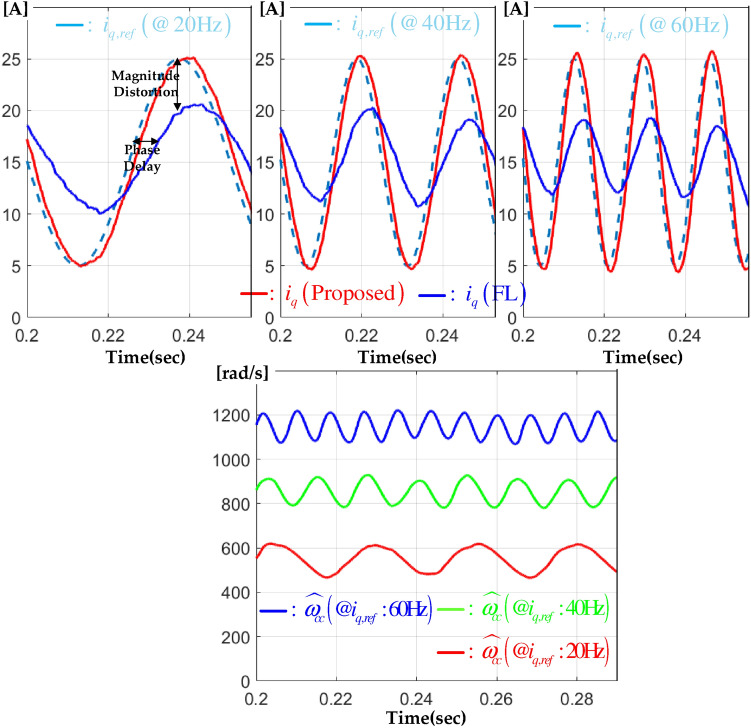
This subsection demonstrates the improvement of frequency response characteristics by the proposed technique under the same setting as the first experiment. To this end, the speed load was set to in a biased sinusoidal form as , , and three kinds of references were applied to the feedback system such that A, Hz. The upper side of Fig. 5 shows the resulting closed-loop current responses, which implies that the proposed technique considerably enhances the frequency response characteristics (e.g., the reductions of magnitude distortion and phase delay) of the feedback system by boosting the bandwidth, accordingly, despite a severe operating mode change. The lower side of Fig. 5 shows the corresponding bandwidth behaviors.
Figure 5.
q-frame current tracking performance comparison result and variable bandwidth behaviors under sinusoidal speed load and sinusoidal references with three kinds of bandwidths, 20, 40, 60 Hz.
Current regulation test under sinusoidal speed load
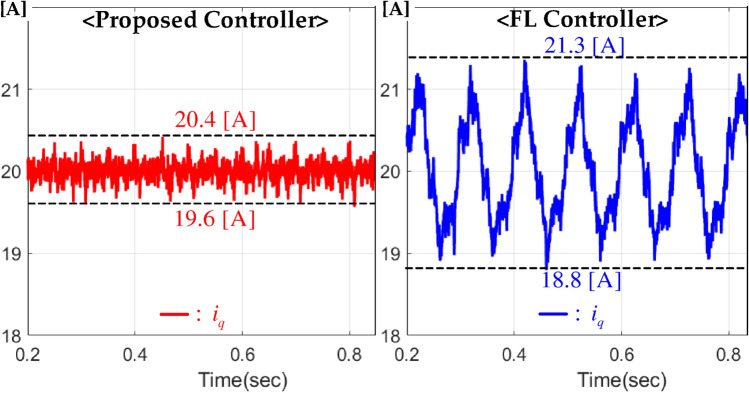
In the third experiment, the q-frame current regulation performance was investigated for A under the time-varying speed load , . As can be seen from Fig. 6, the proposed controller makes the current oscillation smaller about three-times than the FL controller through effective cooperation by the subsystems, such as DOB and online auto-tuner, which leads to a considerable torque ripple reduction resulting in an improved ride comfort for the electrical vehicle applications.
Figure 6.
q-frame current regulation performance comparison under sinusoidal speed load.
Numerical performance comparison result
This subsection concludes this section by presenting the numerical comparison result for the closed-loop performances demonstrated in “Pulse reference tracking test under constant speed load” to “Current regulation test under sinusoidal speed load” sections using the metric function defined as . Here, additional comparison result was included in this numerical performance evaluation using the PI controller tuned for the bandwidth Hz ( rad/s) under the constant speed load rpm. Figure 7 tabulates the numerical performance comparison result showing a 39% performance improvement by the proposed technique. From this experimental evidence, the useful properties proven in “Feedback system analysis results” section were experimentally confirmed, and the proposed technique could be qualified as a promising solution for actual industrial systems, such as home appliances, electric vehicles, and so on.
Figure 7.
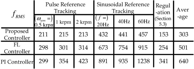
Numerical performance comparison result.
Conclusions
A robust current control technique was suggested for PMSMs, which includes the online auto-tuner and DOBs with closed-loop analysis. The beneficial closed-loop properties obtained by the auto-tuner and DOBs were proven theoretically and experimentally verified by convincing experimental data. Especially, the proposed auto-tuner played a crucial role in improving the current tracking performance and frequency response characteristics in the experimental study by increasing and restoring the closed-loop bandwidth accordingly. In future work, a combination of DOBs and integrators will be devised to secure improved closed-loop robustness with a closed-loop performance optimization process through the order-reduction technique.
Acknowledgements
This work was supported by Korea Institute of Planning and Evaluation for Technology in Food, Agriculture, Forestry(IPET) through Eco-friendly Power Source Application Agricultural Machinery Technology Development Program, funded by Ministry of Agriculture, Food and Rural Affairs(MAFRA)(322047-5).
Author contributions
Software, validation, formal analysis, investigation, and writing-original draft preparation, Y. Kim; Writing-review and editing, data curation, validation, and visualization, H. Choi and J. Park; Supervision, project administration, and funding acquisition, S.-K Kim and Y. Kim; Conceptualization and methodology, S.-K. Kim; resources. All authors have read, reviewed, and agreed to the published version of the manuscript.
Data availability
The datasets used and/or analysed during the current study available from the corresponding author on reasonable request.
Declarations
Competing interests
The authors declare no competing interests.
Footnotes
Publisher’s note
Springer Nature remains neutral with regard to jurisdictional claims in published maps and institutional affiliations.
Contributor Information
Seok-Kyoon Kim, Email: skkim77@adaptivesystem.org.
Yonghoon Kim, Email: yonghun.kim@cnu.ac.kr.
References
- 1.Luo, M. et al. Full-order adaptive sliding mode control with extended state observer for high-speed PMSM speed regulation. Sci. Rep.13, 6200 (2023). [DOI] [PMC free article] [PubMed] [Google Scholar]
- 2.Zhang, B. et al. Fuzzy PID control of permanent magnet synchronous motor electric steering engine by improved beetle antennae search algorithm. Sci. Rep.14, 2898 (2024). [DOI] [PMC free article] [PubMed] [Google Scholar]
- 3.Cao, W. et al. Optimization of x-axis servo drive performance using PSO fuzzy control technique for double-axis dicing saw. Sci. Rep.13, 20719 (2023). [DOI] [PMC free article] [PubMed] [Google Scholar]
- 4.Liu, X. et al. Research on permanent magnet synchronous motor algorithm based on linear nonlinear switching self-disturbance rejection control. Sci. Rep.13, 20133 (2023). [DOI] [PMC free article] [PubMed] [Google Scholar]
- 5.Kim, S.-K. et al. Current sensorless position-tracking control with angular acceleration error observers for hybrid-type stepping motors. Sci. Rep.12, 14993 (2022). [DOI] [PMC free article] [PubMed] [Google Scholar]
- 6.Andeescu, G.-D. et al. Combined flux observer with signal injection enhancement for wide speed range sensorless direct torque control of IPMSM drives. IEEE Trans. Energy Convers.23, 393–402 (2008). [Google Scholar]
- 7.Tang, L., Zhong, L., Rahman, M. & Hu, Y. A novel direct torque control for interior permanent-magnet synchronous machine drive with low ripple in torque and flux—A speed-senseroless approach. IEEE Trans. Ind. Appl.39, 1748–1756 (2003). [Google Scholar]
- 8.Matausek, M. R., Jeftenic, B. I., Miljkovic, D. M. & Bebic, M. Z. Gain scheduling control of DC motor drive with field weakening. IEEE Trans. Ind. Electron.43, 153–162 (1996). [Google Scholar]
- 9.Sul, S.-K. Control of Electric Machine Drive Systems Vol. 88 (Wiley, 2011). [Google Scholar]
- 10.Kwon, Y.-C., Kim, S. & Sul, S.-K. Voltage feedback current control scheme for improved transient performance of permanent magnet synchronous machine drives. IEEE Trans. Ind. Electron.59, 3373–3382 (2012). [Google Scholar]
- 11.Kwon, Y.-C., Kim, S. & Sul, S.-K. Six-step operation of PMSM with instantaneous current control. IEEE Trans. Ind. Appl.50, 2614–2625 (2014). [Google Scholar]
- 12.Srilakshmi, K. et al. Development of renewable energy fed three-level hybrid active filter for ev charging station load using jaya grey wolf optimization. Sci. Rep.14, 4429 (2024). [DOI] [PMC free article] [PubMed] [Google Scholar]
- 13.Wu, X. et al. Adaptive suspension state estimation based on immakf on variable vehicle speed, road roughness grade and sprung mass condition. Sci. Rep.14, 1740 (2024). [DOI] [PMC free article] [PubMed] [Google Scholar]
- 14.Mejia, J. et al. Adaptive filter with Riemannian manifold constraint. Sci. Rep.13, 9014 (2023). [DOI] [PMC free article] [PubMed] [Google Scholar]
- 15.Tian, Y. et al. Application of a long short-term memory neural network algorithm fused with Kalman filter in UWB indoor positioning. Sci. Rep.14, 1925 (2024). [DOI] [PMC free article] [PubMed] [Google Scholar]
- 16.Jezernik, K., Korelic, J. & Horvat, R. PMSM sliding mode FPGA-based control for torque ripple reduction. IEEE Trans. Power Electron.28, 3549–3556 (2013). [Google Scholar]
- 17.Geyer, T., Papafotieu, G. & Morari, M. Model predictive direct torque control-part I: Concept, algorithm and analysis. IEEE Trans. Ind. Electron.56, 1894–1905 (2009). [Google Scholar]
- 18.Papafotieu, G., Kley, J., Papdopoulous, K., Bohren, P. & Morari, M. Model predictive direct torque control-part II: Implementation and experimental evaluation. IEEE Trans. Ind. Electron.56, 1906–1915 (2009). [Google Scholar]
- 19.Chen, W.-H., Ballance, D., Gawthrop, P. & O’Reilly, J. A nonlinear disturbance observer for robotic manipulators. IEEE Trans. Ind. Electron.47, 932–938 (2000). [Google Scholar]
- 20.Son, Y. I., Kim, I. H., Choi, D. S. & Shim, H. Robust cascade control of electric motor drives using dual reduced-order PI observer. IEEE Trans. Ind. Electron.62, 3672–3682 (2015). [Google Scholar]
- 21.Kim, S.-K. Proportional-type performance recovery current tracking control algorithm for permanent magnet synchronous motor. IET Electric Power Appl.12, 332–338 (2018). [Google Scholar]
Associated Data
This section collects any data citations, data availability statements, or supplementary materials included in this article.
Data Availability Statement
The datasets used and/or analysed during the current study available from the corresponding author on reasonable request.


