Abstract
This paper presents a novel state-feedback robust sliding-mode controller (SFRSMC) based on a mixed approach to enhance the control performance of hydraulic turbine governing systems (HTGS) with complex conduit systems under external load disturbances and control signal uncertainties. A state-space model incorporating the dynamic responses of the HTGS is developed. The SFRSMC is designed using the sliding-mode equivalent control principle, with a disturbance observer to estimate and mitigate unknown disturbances. To balance robustness and optimality, mixed linear matrix inequalities (LMIs) are utilized to determine the critical performance sliding matrix via an auxiliary feedback control method. The effectiveness of the proposed control scheme is validated through time-domain simulations under various operating scenarios, including different parameter variations of the HTGS.
Subject terms: Power stations, Hydroelectricity
Introduction
Hydropower, as a clean and sustainable energy source with excellent power storage and flexible regulation capabilities1, is essential in modern renewable energy-based power systems2. Hydropower generating units (HGUs) offer rapid start-up and shutdown, and flexible operating conditions, allowing them to track load changes and serve as backup power during grid emergencies3. Therefore, HGUs are vital for enhancing power system efficiency and maintaining grid safety and stability4.
The hydraulic turbine governing system (HTGS) is the core of the automatic operation of the HGU5. Besides, HTGS is essential for the safe and stable operation of the grid. The task of the HTGS is to maintain the unit’s speed at its rated value by constantly adjusting the HGU’s output power6. In addition, the HTGS also has the task of controlling the start-up and shutdown of the unit. It is important to note that the HTGS is a complex non-linear, time-varying non-minimum phase system integrating fluid, electrical and mechanical components7. Therefore, developing control strategies that improve control quality and provide strong robustness for HTGS is an important task in studying HGU8.
In the past, much work has been done on modeling and control strategies for HTGS. In terms of modeling, the HTGS consists of four main components: turbine, diversion pipe, electric generator, and governor9. In terms of the composition of the HTGS itself, each subsystem is usually non-linear, and it takes work to establish a mathematical model of the HTGS and its subsystems10. In practice, the modeling of HTGS is often necessary to simplify each mathematical model according to the working conditions required11. Recently, the modeling study of complex HTGS has been divided into two categories according to the system conditions: small-fluctuation and large-fluctuation. Small-fluctuation conditions are usually defined as minor disturbances in the system that can be maintained by the governor12. The modeling of systems under small fluctuation conditions can be described by a linearization method because the non-linear factors in the system are not activated. This method is simple, has a clear physical meaning, and meets specific industrial needs13. For HTGS, the transfer function of the mathematical model of the pressure diversion and the turbine system is usually described by a low-order Taylor series expansion of the flow or torque equation14. Therefore, the linearised model of the HTGS is often expressed as a linear matrix or transfer function. In large-fluctuating conditions, such as the opening and closing of the HGU, the system is usually brought into the specified operating state through a wide range of adjustments of the guide vane opening or other device action15. The modeling often takes complete account of the non-linearities in each subsystem to construct a complete non-linear mathematical model of the HTGS16. Therefore, one of the critical tasks of this paper is to develop a mathematical model of the HTGS with complex conduit system that is reasonable.
Advancements in automatic control theory have spurred the development of control strategies for HTGS to meet increasing performance and accuracy demands. Conventional PID control is widely used due to its simplicity and robustness17. However, its effectiveness is limited in complex systems, and PID parameters need to adapt to changes in model parameters. Consequently, PID is often combined with intelligent algorithms, leading to advanced tuning methods like mayfly optimization18, particle swarm optimization19, and artificial bee colony algorithms20. Despite these advancements, PID control struggles to meet all practical engineering demands due to varying field conditions. Thus, adopting advanced control strategies has garnered significant attention among HTGS researchers.
Many advanced control strategies have been applied to control HTGS, such as adaptive control, model predictive control (MPC), fuzzy control, and robust control. Adaptive control methods are typically driven by online detection and correction of data. They can be effectively corrected in real-time when external disturbances or un-modelled dynamics are in the controlled system to achieve the desired control requirements by tracking the trajectory21. This idea is used to improve the regulation system in22, and23. However, adaptive control design requires an iterative learning process, and with an effective learning process, the controller’s performance can be better. MPC is a new type of control strategy with the advantages of solid robustness and low model requirements24. In the field of HTGS, MPC has led to specific research results and has attracted the attention of relevant researchers. In25, HGU’s operation in real-time is presented, and a stochastic MPC algorithm operates with risk control capability. A nonlinear MPC for controlling variable speed hydropower plants is proposed in26. Xu et al. proposes an MPC combined with an adaptive fuzzy control strategy based on an error-compensated model to address the instability of HGU under low head no-load conditions. Experiments show that the controller is feasible under different conditions operating conditions27. The application of MPC to the HTGS achieves good control results. However, given the large number of calculations required for MPC and the poor real-time results, the MPC also has the disadvantage that precise system parameters are required to achieve the desired performance. Fuzzy control, as a control strategy based on fuzzy mathematics and fuzzy logic, has sound control effects in dealing with nonlinear dynamic problems such as time-varying parameters due to its insensitivity to changes in the parameters of the controlled object28. Many scholars have recently used fuzzy control in HTGS. Tian et al. considered the control time delay problem in HTGS and proposed to combine finite-time and fuzzy controllers. The study showed that the controller solved the control time delay existing in HTGS and had better performance compared to traditional PID controllers29. The literature30as well as31combines traditional fuzzy control and its use in HTGS with other intelligent control theories. However, the fuzzy control strategy requires extensive human experience in setting fuzzy rules. All the above work has contributed to studying advanced control strategies for HTGS. When there are uncertainties in the system, such as external disturbances or parameter uptake, robust control can provide effective control, ensuring the stability of the controlled object while giving it good dynamic quality32. The advantage is that there is no need to adjust the controller parameters online, which also ensures that the system has good control performance when the system changes within a certain range33. Therefore, many scholars have applied robust control strategies to the study of control laws of HTGS. In34, a robust controller is designed for a HTGS described by fuzzy nonlinearity. In35, a robust finite-time controller is designed for a fractional-order nonlinear HTGS, and good control results are obtained. The application of robust control strategies can improve the control quality of the HTGS. However, none of these works deal with handling control signals under uncertainty in the HTGS.
Sliding mode control (SMC), as one of the most important strategies in the field of nonlinear control, differs from conventional control in that it forces the system to change according to the current state and move by the predetermined sliding mode state36. SMC is easy to implement with high robustness37. In38, a sliding mode fault-tolerant tracking control method for HTGS is developed based on a nonlinear disturbance observer and back-stepping techniques. In39, the authors design a global fast terminal SMC for an HTGS with an actuator dead zone. However, these methods need to discuss where the control signal fails. Furthermore, the mathematical models discussed need to reflect the state characteristics of the hydraulic system, which is undesirable for applications in HTGS.
As a crucial component of future power systems, HTGS play a significant role in maintaining optimal regulation and control performance, even in the presence of uncertainties in the control signal and a multitude of random load disturbance40. However, further research is needed to address the specific challenges posed by HTGS with uncertain control signals. To fill this research gap, this paper introduces a novel approach called state feedback robust sliding mode control (SFRSMC) based on a mixed methodology for controlling HTGS. The proposed controller offers several notable advantages. Firstly, it effectively handles the uncertainty in the control signal of HTGS by utilizing SMC, a robust control technique capable of mitigating internal disturbances and unmodeled dynamics. This fault-tolerant characteristic is crucial for ensuring reliable regulation and control performance. Secondly, the proposed controller exhibits excellent immunity to external disturbances and achieves optimal control performance. This is achieved by incorporating the mixed control approach into SFRSMC using linear matrix inequalities (LMIs). While traditional control methods are widely used for optimizing control system performance, they often lack robustness against external disturbances and variations in system parameters41. Conversely, control methods tend to be overly conservative, trading off other aspects of system performance to address uncertainty in system parameters42. By combining the strengths of both approaches, the mixed control allows for robustness and optimal performance integration within the controller. Since its introduction43, researchers have explored various applications of this control method44. As a result, the proposed SFRSMC based on the mixed approach achieves a remarkable balance between optimal transient performance and robustness against control uncertainties and external disturbances. The main novelties and contributions of this paper can be categorized as follows:
A novel state-space differential equation model reflecting the full hydro-mechanical-electrical state of a HTGS is developed;
A SFRSMC based on the method is proposed;
Damping the state oscillations against disturbances and uncertainties;
Excellent damping efficiency, especially low overshoot, steady-state error, and settling time;
Various scenarios verify the advantages of the proposed method.
The rest of the paper is structured as follows. Section 2 presents a mathematical model described by state-space for the HTGS with complex conduit system. A novel SFRSMC based on the mixed method is proposed in Section 3. Section 4 presents the simulation analysis. Finally, the main conclusions of this paper and future works are summarized and prospected in section 5.
Mathematical modeling of HTGS
The structure of a typical HGU is shown in Fig. 1. The HTGS with complex conduit system consists of components such as the upstream reservoir, the diversion tunnel, the upstream surge tank, the pressure steel penstock, the turbine, the draft tube, the downstream surge tank, the tailrace tunnel, and the downstream reservoir. Therefore, the HTGS is a complex hydro-mechanical-electric coupled system consisting of a turbine and a generation. This section describes the mathematical modeling methods for each link of the HTGS system and the system’s state space differential equation model.
Fig. 1.
Schematic diagram of typical HGU structure.
Pipeline modeling
It is generally accepted that in the case of small fluctuations in the regulation system, the rigid water hammer model can be used to meet the engineering error requirements45. Fig. 2 shows the modeled pipe object. According to the rigid water hammer theory, the water strike pressure wave propagates instantaneously throughout the pressure diversion pipe, and the change in water level at the end of the pipe can be described as:
| 1 |
where is the pipeline loss; is the water level deviation at the end of the pipeline; is the flow in the pipeline; is the length of the pipeline; is the cross-sectional area of the pipeline; and g is the acceleration of gravity.
Fig. 2.
Diagram of pipeline and surge tank.
Linearizing Eq. (1) around the steady state flow value , then one obtains
| 2 |
Next, taking the relative value of Eq. (2) obtains
| 3 |
where is the water hammer time constant of pipeline; is the relative value of the pipeline loss; is the relative water level deviation of the pipeline; is the relative flow deviation of the pipeline.
Surge tank modeling
Fig. 2 shows the modeled object surge tank. The following differential equation can describe the dynamic equation for a surge tank:
| 4 |
where is the water level deviation of surge tank; is the flow deviation of surge tank; and is the cross-sectional area of the surge tank.
Similarly, taking the relative value of Eq. (4) obtain:
| 5 |
where is the time constant of the surge tank; is the relative flow deviation of the surge tank; is the relative water level deviation of the surge tank.
Integral pipeline model
As shown in Fig. 1, the diversion tunnel connects the upper reservoir of the HGU to the upstream surge tank. Using Eq. (3), the dynamic relationship of the diversion tunnel is described by the following mathematical model:
| 6 |
where is the time constant of the diversion tunnel; is the relative water level deviation of the diversion tunnel; is the relative flow deviation of the diversion tunnel; is the relative head loss of the diversion tunnel.
The upstream surge tank is located upstream of the HGU, which plays a role in reducing the negative response of the diversion tunnel water hammer; the downstream surge tank is located downstream of the HGU, which reduces the negative response of the tailrace tunnel water hammer. The dynamic response of the upstream surge tank can be described by the mathematical model of the differential equation derived from Eq. (5) as:
| 7 |
where is the time constant of the upstream surge tank; is the relative water level deviation of the upstream surge tank; the relative flow deviation of the upstream surge tank.
Similarly, a mathematical model of the dynamic response of the downstream surge tank dynamics can be described as:
| 8 |
where is the time constant of the downstream surge tank; is the relative water level deviation of the downstream surge tank; the relative flow deviation of the downstream surge tank.
As shown in Fig. 1, the penstock connects the surge tank of the upper reservoir to the turbine, the spiral case inlet, and the draft tube connects the turbine flow outlet to the surge tank of the lower reservoir. Compared to the entire piping system of the HGU, the length of the penstock and the draft tube is relatively short. Therefore, when the HGU is in turbine operation, the dynamic processes of the penstock and the draft tube are unified into one model and described by the differential equation as:
| 9 |
where is the sum of the time constants of the penstock and the draft tube; is the relative flow deviation of the pipe; is the relative water level deviation of the pipe; is the relative head loss of the pipe.
The tailrace tunnel connects the surge tank of lower reservoir to the downstream reservoir and its dynamic response is described by the differential equation:
| 10 |
where is the time constant of the tailrace tunnel; is the relative water level deviation of the tailrace tunnel; the relative flow deviation of the tailrace tunnel; is the relative head loss of the tailrace tunnel.
Based on the structure of the HGU depicted in Fig. 1, the following equation for the flow at the connection in the surge tanks of the lower/upper reservoir can be obtained from the continuity of fluid:
| 11 |
Hydraulic turbine modeling
When the HGU is in rated operating condition, the relative head deviation of the turbine is the sum of the relative water level deviation in the downstream surge tank and the relative water level deviation of the tailrace tunnel . Similarly, from the fluid continuity it is known that the relative flow deviation of the turbine is equal to the relative flow deviation of the tailrace tunnel , which can be described by the mathematical expression:
| 12 |
In addition, the small signal model for the turbine relative torque deviation and the relative flow deviation when the HGU is operating in the generation direction can be expressed as:
| 13 |
where y is the relative value deviation of the guide vane opening; are the first order derivatives of the mechanical torque to the guide vane opening, speed and head, respectively; are the first order derivatives of the flow rate to the opening, speed and head, respectively; when the unit is operating in the power generation, the effect of the variation of the hydraulic turbine speed on the flow rate is small, that is .
Remaining components modeling
In the study of HTGS, the synchronous generator model is reduced to a first-order inertia link characterizing the rigid motion of the rotor shaft, which can be expressed as:
| 14 |
where is the relative value of load deviation; is the time constant of the the synchronous generator; is the load self-regulation factor of the synchronous generator.
The servo-mechanism of the HTGS uses a first-order inertial link whose transfer function is shown as:
| 15 |
where is the time constant of the servo-mechanism system; y is the time constant of servo-mechanism; u is the control signal output from the controller.
Overall modeling of HTGS
After thoroughly analyzing the HTGS system, it becomes evident that its operation can be delineated into three distinct and interconnected parts, each playing a vital role in its overall functionality and performance. Part I encompasses the governor, which consists of the controller and the servo-mechanism. Acting as the regulatory hub, the governor oversees the system’s dynamic balance. It facilitates precise control by continuously monitoring and adjusting the system’s response based on the measured outputs. Part II comprises the turbine and the hydraulic system, which incorporates upstream and downstream surge tanks. These essential components form the backbone of the HTGS, which is responsible for effectively managing fluid flow and pressure. The turbine actively adjusts its operating conditions to meet the demand for power generation. At the same time, the hydraulic system, including the surge tanks, aids in maintaining the stability of the system by mitigating pressure fluctuations. Together, they provide a robust and reliable infrastructure that enables the HTGS system to respond promptly and efficiently to varying load demands, ensuring a consistent power output. Lastly, Part III encompasses the model of the generation, which is discussed earlier.
Consequently, to mathematically describe the HTGS system as a set of linear state-space differential equations, it is necessary to identify and select the pertinent physical state quantities that can be measured and tracked in real time. This paper selecte state variables include x, y, , , , , and . Each of these quantities plays a specific role in understanding the dynamics of the HTGS under operating conditions. Therefore, the HTGS model in the form of a state differential is
| 16 |
where the state vector , the coefficient matrix , , and are defined as follows:
;
;
;
.
where . For the matrices , and the internal parameters are defined as follows: , , , , , , , , , , , , , , , , , , , , , , , , , and .
The frequent regulation of HTGS often leads to various degrees of deterioration in its performance. When non-extreme faults occur, the HTGS exhibits insufficient regulation control, resulting in uncertainty and disturbances in the output signal of the controller. To address these challenges, this model represents the dynamic behavior of the system using state space differential equations, considering both the uncertainty in the controller’s output signal and external input disturbances . The modified dynamic system can be expressed as follows:
| 17 |
where represents the state variable, is the system matrix, and and are the matrices for the system control input and perturbation input, respectively. The system is subject to constraints, such that , where represents the allowable range of uncertainty in the controller’s output signal.
By introducing this modified dynamic model, we aim to improve the regulation performance of the HTGS and address the issues related to uncertainties and disturbances in the control process. This enhanced model allows us to gain a better understanding of the system’s behavior and devise more effective control strategies for stable and reliable operation.
Design of state-feedback robust sliding-mode controller for HTGS
Design process of the controller
The HTGS model considering the control signal uncertainty of the dynamic system as well as external input disturbances is described by Eq. (17). This paper combines equivalent-based SMC theory and auxiliary feedback-based SMC analysis to design a SFRSMC in HTGS.
In this paper, we introduce the concept of the sliding surface for the HTGS. The sliding surface is associated with the system state vector and is defined as follows:
| 18 |
where represents the transpose of the control input matrix, and is a positive definite matrix. The choice of the positive definite matrix is critical for achieving the necessary control properties in the HTGS.
By rationally designing the sliding matrix , we can ensure that the sliding surface exhibits desirable behavior, leading to effective regulation and stabilization of the HGU. The ultimate goal is to achieve as the system state vector converges to the desired state, thereby ensuring proper regulation and stability in the HTGS.
For the HTGS, the mathematical expression of the SFRSMC designed in this paper can be described as:
| 19 |
where is the equivalent-based control law; is the robust control law.
According to the equivalent control principle, and by taking , we can obtain from Eq. (16) and the following expressions:
| 20 |
Consequently, the equivalent-based control law can be determined as follows:
| 21 |
Furthermore, according to the design principle of SMC, to ensure that , the robust control law in the controller output is defined as follows:
| 22 |
where is the switching gain; is the symbolic function.
Next, the dynamics of the sliding surface is analysed by the Lyapunov’s stability theorem, and the Lyapunov function is chosen as:
| 23 |
The derivative of the sliding surface is obtained:
| 24 |
Then, the derivative of the Lyapunov function defined by Eq. (23) is obtained:
| 25 |
According to Lyapunov’s stability theorem, when , when , it is possible to make .
In conclusion, the mathematical expression of the SFRSMC for the HTGS is obtained by combining Eq. (21) and Eq. (22):
| 26 |
In this expression, a combination of terms determines the control input u. The first part is derived from the equivalent-based control law . This term ensures that the control law steers the system toward the desired sliding surface and tracks the reference state. The second part incorporates the sliding-mode robust control aspect of the SFRSMC strategy. It introduces a sliding mode approach to enhance robustness against uncertainties and disturbances in the HTGS. The final control law given by Eq. (26) provides a practical and robust approach for regulating the HGU and achieving stability and precise control in the HTGS operation.
SMC analysis of auxiliary feedback-based
The above analysis shows that the design of the symmetric positive definite matrix has a decisive influence on the control performance of state feedback. In this paper, we refer to? for the design idea of SMC analysis based on auxiliary feedback. Based on this idea, we innovatively introduce the mixed LMI to design the silding matrix so that the controller has optimal regulation and the best robustness performance. First, the mathematical expression of the controller is rewritten as:
| 27 |
where .
After incorporating the rewritten controller given by Eq. (27) into the state-space equations described by Eq. (17), the closed-loop system is obtained as follows:
| 28 |
where ; .
For the dynamical system described by Eq. (28), two sets of control performance output vectors are added, one for the control performance output vector and one for the control performance output vector, to obtain the following augmented dynamical system:
| 29 |
where , are the and control performance output vectors, respectively.
In this augmented system, we have two control performance output vectors and , which are influenced by the matrix , , , and , respectively. The augmented dynamical system, described by Eq. (29), allows us to analyze and design the controller based on different control performance criteria, specifically, and control performance, providing a comprehensive framework for controlling and optimizing the HTGS concerning these performance objectives. In this paper, the weighting matrix , , , , and in Eq. (29) is defined as:
| 30 |
These matrices , , , and are the systematic coefficient matrices of the appropriate dimensions; it should be noted that , , , , and are defined in this paper as:
| 31 |
where 0 (, , 8) and are the weighting factors.
According to the sliding surface defined in this paper, the matrix mainly serves to organize and fuse the state feedback information of the controlled object. Based on this idea, this paper defines the relationship between the state feedback matrix and the positive definite matrix in (28) as . The matrix is solved by designing a suitable matrix such that the controlled object described by Eq. (28) has mixed control performance. The mixed control performance requires that the closed-loop system meets the following performance:
1) robustess performance, the closed-loop transfer function from to satisfies:
| 32 |
The performance by a feedback gain matrix is achieved if and only if the matrices and exist and the following LMI is satisfied:
| 33 |
where .
2) dynamic response performance, the closed-loop transfer function from to satisfies:
| 34 |
The performance by a feedback gain matrix is achieved if and only if the matrices , , and exist and the following LMI is satisfied:
| 35 |
where is the trace of matrix .
For convenience, let us set and . The closed-loop feedback gain matrix by that simultaneously satisfies the performance required by stability, robustness performance, and dynamic response, which has a solution if there exist sliding mode surface matrix , a symmetric matrice and a matrix , satisfying:
| 36 |
where and are the weighting factors.
Perturbation observer for SFRSMC
It is not possible to construct a controller directly using Eq. (26) because the equivalent-based control law described by Eq. (26) has a composite unknown disturbance term d. It should be noted that if the complex unknown disturbance term d is removed and the controller is constructed by selecting a large enough switching gain to cancel the effect of the complex unknown disturbance term d, which leads to two problems:
The controller can only withstand a limited number of control inputs due to practical constraints;
The discontinuity of the control inputs will cause high-frequency jitter in the system, which is not conducive to the stability of the system.
Therefore, the magnitude of the unknown composite disturbance d needs to be estimated by the disturbance observer and feedback to the controller to actively reduce the impact of the unknown composite disturbance on the system, thus improving the robustness of the controlled system. Therefore, accurate reconstruction of the composite unknown disturbance d is the key to achieving the excellent performance of the controller.
When the perturbation term changes slowly, it can be assumed that is satisfied, then the conventional perturbation observer can be designed as:
| 37 |
where is an estimate of the external disturbance d to the system, and is the disturbance observer gain.
To enhance the robustness of the system, the error compensation term is introduced and the perturbation observer can be designed as:
| 38 |
From Eqs. (37) and (38) the error dynamics equation for the perturbed observer can be expressed as:
| 39 |
As the derivatives of the state variables in Eq. (38) cannot be measured directly, finding the derivatives would amplify the noise of the state variables and affect the effectiveness of the observer. Therefore, a perturbation observer designed with the help of intermediate auxiliary variable is proposed as:
| 40 |
The improved expression for the perturbation observer is then obtained by deriving the intermediate auxiliary variable as:
| 41 |
Eq. (41) shows that with the help of the intermediate variable z, the perturbation observer does not need to calculate the state variable differentiation and does not cause noise amplification during the observation process, which is easy to implement in engineering.
Proof: To demonstrate the asymptotic convergence of the observation error to 0 when the observer gain , we choose the following Lyapunov function:
| 42 |
Taking the time derivative of Eq. (42), we have:
| 43 |
From Eq. (43), it can be seen that when the observer gains matrix , the designed observer is stable.
In summary, by selecting a positive observer gain matrix , the observation error will converge asymptotically to 0, confirming the stability of the designed perturbation observer described by Eq. (41). This stability property ensures accurate reconstruction of the composite unknown disturbance d, contributing to the overall robustness and excellent performance of the controller for the HTGS system.
When the system is modeled with high uncertainty and disturbances, the gain of the switching term needs to be large, and this causes large jitter. To prevent jitter, the saturation function is used instead of the symbolic function in the controller in this paper.
| 44 |
where is the boundary layer thickness.
The saturation function described by Eq. (44) enables the SFRSMC to use switching control outside the boundary layer and feedback control inside the boundary layer. Therefore SFRSMC makes the control state of the system stabilize quickly during control and reduces jitter during sliding mode switching.
Numerical study
Simulation parameters
In this section, a simulation of the control process of the unit load variation under generation conditions is presented to verify the advancedness of the control strategy proposed in this paper. It should be noted that the scope of this paper is to study the SFRSMC of a HTGS. Therefore, only the operation of a single tube and single machine structure of a HTGS is discussed. Our discussion is limited to this specific configuration. During the simulation, we utilize specific simulation coefficients corresponding to the rated states of the HTGS. As detailed in Table 1, these simulation coefficients serve as crucial reference parameters for the simulation process.
Table 1.
Parameters of the considered HTGS.
| Parameter | Value |
|---|---|
| (Time constant of upstream surge tank) | 475.948(s) |
| (Time constant of downstream surge tank) | 2500(s) |
| (Time constant of diversion tunnel) | 3.220(s) |
| (Relative head loss of diversion tunnel) | 0.026 |
| (Sum of the time constants of penstock and draft tube) | 0.82(s) |
| (Relative head loss of the pipe) | 0.010 |
| (Time constant of tailrace tunnel) | 0.26(s) |
| (Relative head loss of tailrace tunnel) | 0.015 |
| (Time constant of servo-mechanism system) | 0.2(s) |
| (Time constant of synchronous generator-motor) | 8.5(s) |
| (Transfer coefficients of turbine) | −1.000,1.500,1.000 |
| (Transfer coefficients of turbine) | 0.5,1.000,0 |
| (Self-regulation factor of synchronous generator-motor) | 0.210 |
To verify the advancedness of the developed control strategy, a fair comparison of the PID controller, robust controller, robust controller, and the proposed controller is carried out on the HTGS.
PID controller: This paper uses a typical PID controller, which can be described mathematically as: . The parameters , , and were thoroughly selected and adjusted to the performance requirements using the control system design tool in MATLAB. This paper sets these three parameters to 16.090, 12.230, and 3.653, respectively.
robust controller: The design problem of this controller is to build an optimal state feedback controller for the system to minimize the level of attenuation from the disturbance to the output. The feedback matrix in the state feedback controller of the optimal robust controller designed in this paper is .
robust controller: This controller is designed similarly to the robust controller. The optimal state feedback controller to minimize the level of attenuation from the disturbance to the output is . The feedback matrix in the state feedback controller of the optimal robust controller designed in this paper is .
- The proposed controller: The relevant control parameters are: , , and . The disturbance observer gain matrix is . The weight coefficients in Eq. (31) are , , , , , , , , and . The, The sliding matrix can be obtained by designing suitable weighting coefficients and calculating the LMI shown in Eq. (45) as:
45
where the matrix and are shown below:
Simulation results
Test system 1
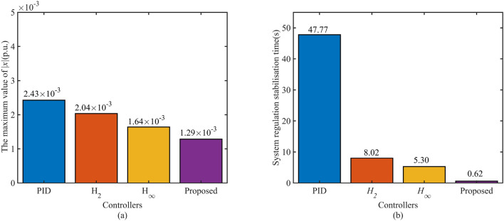
The HTGS system is simulated with step 0.1 p.u. size load disturbance response. The simulation time is set to 500 s. The 0.1 p.u. size load disturbance is introduced at 10 s of the simulation time. The response curves for the states x and y of the HTGS are shown in Fig. 3. Fig. 3-(b) shows that the dynamic process of the HTGS under different controllers is basically the same, and the dynamic response of the servo-hydraulic system under the proposed controller is more moderate than that of the robust controller. The most important comparison is shown in Fig. 3-(a), which shows the speed response curves of the HTGS with different controllers. The detailed performance indicators of the HTGS with different controllers, the maximum speed values during regulation, and the comparison of the regulation time bars are shown in Fig. 4. The proposed controller is 47.15s faster than the PID controller and 7.4s and 4.68s faster than the and robust controllers, respectively. The performance comparison shown in Fig. 4 fully demonstrates the speed advantage of the proposed controller. The overshoot of the proposed controller is also minimal, which indicates better smoothness in the dynamic process and higher steady-state accuracy, confirming the robustness of the proposed controller.
Fig. 3.
System speed response curves under step load perturbation.
Fig. 4.
Maximum speed and regulation time of the regulation process under step load disturbance.
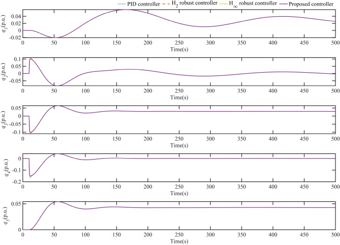
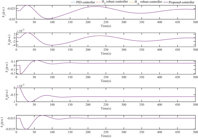
Fig. 5 shows the variation curves of all flow state quantities in HTGS for different controllers. It is clear from these plots that the process of all flow state variables remains essentially the same regardless of the controller used in the HTGS. However, with the proposed controller, the maximum value of all flow state quantities in the HTGS is slightly reduced during the regulation process. The variation curves of all water level state quantities in the HTGS are shown in Fig. 6. The water level dynamics depicted in Fig. 6 are also generally consistent. In Fig. 5 and Fig. 6, the two-state quantities and reach their maximum values when the system simulation reaches 11 s. These maximum values are reduced when HTGS uses the controller proposed in this paper. In particular, the maximum value of is reduced to −0.2 compared to −0.22 with the PID control. The simulations in Figs. 5 and 6 also show that the flow and pressure variation in each part of the HGU pipeline is essentially the same regardless of the control strategy used. However, the maximum values of these quantities are still reduced using the control strategy proposed in this paper.
Fig. 5.
Flow change curve for each component of HGU during regulation.
Fig. 6.
Water level change curve for each component of HGU during regulation.
The incorporation of critical flow and water level in the system into the feedback control system is an essential consideration for improving the control performance of the HTGS. The plots also illustrate that a key idea for improving the control performance of HTGS is to incorporate critical flow and water level variations in the hydraulic system.
Test system 2
Due to the grid integration of new energy sources such as wind power and photovoltaic power, the disturbances d faced by HTGS are more random. From Fig. 7, it can be seen that the tracking time of the designed disturbance observer is less than 0.1s and the steady-state error of the observed value is less than 0.001 for the load disturbance signal d integrated into HTGS, which satisfies the performance requirements of the observer.
Fig. 7.
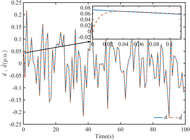
System input disturbance and observations from the improved disturbance observer.
The random load disturbance signal shown in Fig. 8 is applied to the HTGS to test the robustness of the proposed controller. In addition, the fault tolerance of the controller refers to the ability of the system to withstand disturbances in the presence of signal uncertainty in the control signal. To verify the fault tolerance of HTGS, a signal uncertainty perturbation is introduced when the simulation reaches 65s, and the perturbation is withdrawn at 75s. The loading time of the signal uncertainty lasts for 10s.
Fig. 8.
System x and y response curves under random load and control signal uncertainty perturbations.
The simulation results of the system speed of HTGS under different controllers are shown in Fig. 8-(a). From Fig. 8-(a), it can be seen that when the system is subjected to random load disturbance, the speed fluctuation of HTGS with the proposed controller is significantly smaller than that of PID, , and controllers. When the simulation time is 70 s, the maximum value of the HTGS speed deviation is close to 0.01 p.u. with the PID control due to the uncertainty of the control signal loading, while the speed deviation with the and controls is almost the same. However, the proposed control has a tiny speed deviation range and a very short control stabilization time. Therefore, SFRSMC can effectively reduce the frequency fluctuations of the grid system regulated by the HGU, and it shortens the stabilization time of the HTGS, which is a great impetus to improve the robustness of the power system and enhance the safe and stable operation of the HGU.
In this paper, the error integration criterion is used to quantify the proposed controller’s improvement of the HTGS control performance. As a measure of the performance of a control system, the error integration criterion is obtained by integrating the deviation of the desired output signal from the actual output signal. In the field of control engineering, the common error integration criteria are shown in Table 2.
Table 2.
Error integration criteria.
| Criterion | Mathematical expression | Advantages |
|---|---|---|
| Integral of absolute error (IAE) | Good transient response performance | |
| Integral of time-absolute error (ITAE) | Good transient response and good parameter selectivity | |
| Integral of the square error (ISE) | Fast response time | |
| Integral of time square error (ITSE) | Suppressing deviations after transient response of the system |
The performance metrics are calculated using the error integration criteria shown in Table 2, and the performance of the controllers is compared. For the same perturbations, the speed response of the controllers based on the error integral criterion is shown in Fig. 9. According to the comparison in Fig. 9, the SFRSMC controller has significantly lower values than the PID, , and controllers when the HTGS is subjected to various perturbations, which shows that the proposed SFRSMC controller has good global stability in terms of the dynamic performance of the system. In addition, from Fig. 9, it can be seen that the response of the proposed controller is significantly better than other types of controllers, both in terms of the rise time of the system subjected to the controller action and the regulation time of the controller after the disturbance.
Fig. 9.
IAE, ISE, ITAE and ITSE values during system regulation.
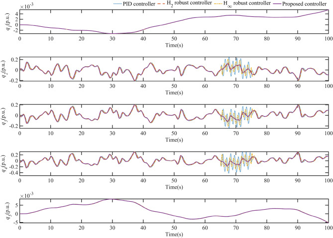
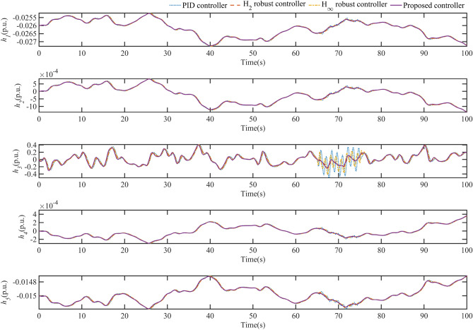
Fig. 10 shows the dynamics of the HTGS flow in each part of the HGU under the perturbations shown in this case with different controllers. As seen in Fig. 10, the changes in and are essentially the same for the different controllers. The dynamic response of and is not significant when the uncertainty of the system control signal is loaded. In contrast, the changes in , , and are very pronounced, especially when the control signal uncertainty is loaded at 65 seconds. Thanks to the excellent fault tolerance of the proposed SFRSMC, the system HTGS changes very smoothly under the SFRSMC controller for , , and . Fig. 11 shows the water level dynamic response of different controllers for each part of the HGU under the perturbation in this case. From Fig. 11, it can be seen that there is no significant difference in the dynamics of , , , and between the different controllers. In contrast, the dynamics of are very drastic and can be interpreted as the pressure change at the inlet of the worm. The proposed controller can effectively reduce the pressure fluctuation at the wormhole inlet and improve the safe operation of the HGU.
Fig. 10.
Flow change curve for each component of HGU during regulation.
Fig. 11.
Water level change curve for each component of HGU during regulation.
As seen in Figs. 10 and 11, for the HTGS, which is involved in the frequency regulation of grid loads containing wind and photovoltaic power, the different controller designs cannot change the hydrodynamic processes in the HGU to any great extent. In addition, increasing the fault tolerance of the controller in the HTGS can effectively reduce the dynamic variation of the flow and water pressure at the turbine inlet.
Robustness against system parameters changes
In this subsection, the main mechanical parameters , the main hydraulic parameter , and the main electrical parameter are varied in the HTGS, and the operating conditions of the HTGS are kept constant throughout the simulation (by adjusting the 0.1 p.u. load). The HTGS’s response to these parameter changes with different controllers is observed to verify the robustness of the proposed controller in dealing with the uncertainty of the parameters of the controlled object.
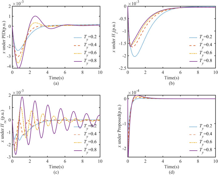
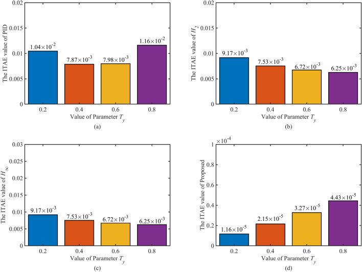
The time constant of the servo-hydraulic system in the HTGS becomes more prominent as the system ages. The speed response of the HTGS for different values of is shown in Fig. 12. As shown in Fig. 12, the system under PID and control oscillates as the time constant increases. In particular, since the controller is designed to resist external input disturbances, the controller could be more effective in dealing with such perturbations due to parameter ingestion. The controller is based on the optimal design of the regulation process, which can maintain a certain level of robustness in this case. The controllers designed in this paper can maintain a minimum amount of overshoot and a minimal regulation time for different parameters. The results of the comparative metrics of these controllers are shown in Table 3. In addition, the calculated IATE values of the various controllers for the regulation process at different are shown in Fig. 13. Both Table 3 and Fig. 13 show that the proposed control spheres can handle the problems associated with the aging of servo-hydraulic systems.
Fig. 12.
Performance of controllers in speed oscillations when is changed.
Table 3.
Key indicators of dynamic response under changes.
| Controller | Value of Parameter | Settling time (s) | Undershoot (p.u.) |
|---|---|---|---|
| PID controller | 0.2 | >10 | |
| 0.4 | >10 | ||
| 0.6 | >10 | ||
| 0.8 | >10 | ||
| Controller | 0.2 | 5.925 | |
| 0.4 | 6.266 | ||
| 0.6 | 4.607 | ||
| 0.8 | 4.904 | ||
| Controller | 0.2 | 4.511 | |
| 0.4 | 5.625 | ||
| 0.6 | 7.503 | ||
| 0.8 | >10 | ||
| Proposed controller | 0.2 | 0.491 | |
| 0.4 | 0.527 | ||
| 0.6 | 0.366 | ||
| 0.8 | 0.311 |
Fig. 13.
The ITAE value of controllers when is changed.
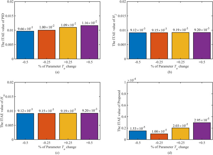
is the mechanical inertia time constant of HTGS, and to understand the robustness of the proposed SFRSMC, in this section, the responses of the PID, , , and SFRSMC controllers are evaluated under the variation of the mechanical inertia time constant of the system. To this end, the parameter is varied to investigate the controller’s performance. is varied to its nominal values of , , , and . In this case, the speed oscillation of the HTGS is depicted in Fig. 14. As seen from the increase in , the speed oscillations controlled by the SFRSMC are always absent compared to other controllers. The SFRSMC is effective in suppressing oscillations in the case of increasing or decreasing . A detailed comparison table of the quantified values is shown in Table 4. As seen from the table, the proposed controller provides a better solution than the other three controllers in all cases, both in terms of stability time and absolute maximum downwash. Fig. 15 shows the ITAE values of the HTGS regulation process for the different Ta controllers. In the two worst cases of and parameter uncertainty, the proposed controller maintains the IATE values of the order of , demonstrating the proposed controller’s optimal regulation and robustness.
Fig. 14.
Performance of controller in speed oscillations when is changed.
Table 4.
Key indicators of dynamic response under changes.
| Controller | of parameterchange | Settling time (s) | Undershoot (p.u.) |
|---|---|---|---|
| PID controller | >10 | ||
| >10 | |||
| >10 | |||
| >10 | |||
| Controller | 7.093 | ||
| 6.745 | |||
| 6.300 | |||
| 5.708 | |||
| Controller | 5.570 | ||
| 5.392 | |||
| 4.484 | |||
| 4.308 | |||
| Proposed controller | 0.311 | ||
| 0.305 | |||
| 0.402 | |||
| 0.503 |
Fig. 15.
The ITAE value of the controller when is changed.
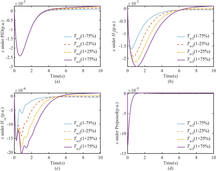
The inertia time constant of the diversion pipe is a fundamental constant in HTGS. This paper uses the time constant to model the inertia of the penstock and the draft tube of the HTGS. Therefore, the actual of the HTGS will deviate from the nominal given in this paper. The time constant Tw3 is the main factor that directly affects the dynamic characteristics of the regulating system. Therefore, it is necessary to investigate the dynamic response of the HTGS under a change in .
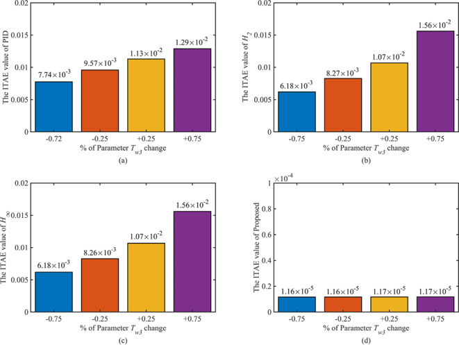
As shown in Fig. 16, this graph illustrates the dynamic response of the HTGS for the different controllers studied with varying . It is easy to see that for the HTGS controlled by the PID controller, there is a risk of the system becoming unstable as increases, and is a direct factor in the deterioration of the dynamic quality. For the HTGS with both and robust controllers, the maximum speed response of the HTGS starts to become more prominent, and the regulation time becomes longer as increases. However, with the proposed controller, the dynamic response of the HTGS is always excellent, with short overshoot and regulation time. The IATE values for the corresponding regulation process are calculated, and the ITAE of the four controllers are summarised in the bar chart shown in Fig. 17 as a function of . It can be seen from the graph that the proposed control can keep the ITAE at a minimal value regardless of the change in , which also shows the excellent control accuracy and fast convergence of the HTGS under SFRSMC control. In addition, the dynamics of HTGS in various controllers with varying are summarized in Table 5 in terms of regulation time and overshoot.
Fig. 16.
Performance of controller in speed oscillations when is changed.
Fig. 17.
The ITAE value of the controller when is changed.
Table 5.
Key indicators of dynamic response under changes.
| Controller | of Parameterchange | Settling time (s) | Undershoot (p.u.) |
|---|---|---|---|
| PID controller | >10 | ||
| >10 | |||
| >10 | |||
| >10 | |||
| Controller | 6.433 | ||
| 7.154 | |||
| 8.014 | |||
| >10 | |||
| Controller | 4.963 | ||
| 5.79 | |||
| 7.094 | |||
| >10 | |||
| Proposed controller | 0.9027 | ||
| 0.9027 | |||
| 0.9027 | |||
| 0.9027 |
Conclusions
Due to their technical, environmental, and economic benefits, hydropower generating units (HGUs) will be widely integrated into future power systems, providing a solid guarantee for efficient, low-carbon, and sustainable operation. However, the significant randomness of new power system loads and renewable energy sources can cause frequency oscillations in the grid, which appropriate controllers for hydraulic turbine governing systems (HTGS) should suppress.
In this paper, a novel state-space mathematical model for HTGS with complex conduit systems is proposed. A state-feedback robust sliding-mode controller (SFRSMC) based on a mixed method is designed to control the HTGS in islanding mode. Specifically, a mixed linear matrix inequality (LMI) approach is utilized for the optimal tuning of the sliding matrix in the SFRSMC. This new SFRSMC effectively dampens unit speed oscillations caused by the intermittent nature of renewable energy sources and load variations. Simulation results demonstrate that the proposed SFRSMC significantly outperforms conventional PID, , and controllers in terms of damping characteristics such as maximum overshoot, settling time, and integral of absolute error. Additionally, the robustness of the proposed method against system parameter variations is verified.
Despite the promising results, the proposed control strategy has been validated only through simulations under specific operating conditions. Practical implementation may encounter challenges such as unmodeled dynamics, external disturbances, and hardware limitations. Therefore, future research will focus on applying the SFRSMC based on the mixed method to control HTGS in real engineering applications. Further studies will also aim to address the control of HTGS under grid-connected mode and consider the impact of communication delays and network constraints in distributed control scenarios.
Acknowledgements
This work is supported by grants from the National Natural Science Foundation of China (No. 52079059 & No. 52269020).
Author contributions
Dao Fang: Investigation, Methodology, Software, Writing - original draft, Writing - review & editing. Yidong Zou: Validation, Simulation , and Writing- Reviewing. Jing Qian: Software, Validation. Yun Zeng: Writing- Reviewing, Editing, and Supervision.
Data availibility
The data presented in this study are available on request from the corresponding author.
Declarations
Competing interests
The authors declare no competing interests.
Footnotes
Publisher’s note
Springer Nature remains neutral with regard to jurisdictional claims in published maps and institutional affiliations.
these authors contributed equally to this work.
References
- 1.Sakti, A. D. et al. Spatial integration framework of solar, wind, and hydropower energy potential in Southeast Asia[J]. Scientific Reports13(1), 340 (2023). [DOI] [PMC free article] [PubMed] [Google Scholar]
- 2.Samare Hashemi, S. M., Robati, A. & Kazerooni, M. A. Applying the new multi-objective algorithms for the operation of a multi-reservoir system in hydropower plants[J]. Scientific Reports14(1), 3607 (2024). [DOI] [PMC free article] [PubMed] [Google Scholar]
- 3.Chen, J., Zeng, Q., Zou, Y., et al. Intelligent robust control for nonlinear complex hydro-turbine regulation system based on a novel state space equation and dynamic feedback linearization[J]. Energy, 2024: 131798.
- 4.Chen, J. et al. Generalized predictive control application scheme for nonlinear hydro-turbine regulation system: Based on a precise novel control structure[J]. Energy296, 130916 (2024). [Google Scholar]
- 5.Wang, P. et al. Ultra-low frequency oscillation analysis considering thermal-hydro power proportion[J]. International Journal of Electrical Power & Energy Systems148, 108919 (2023). [Google Scholar]
- 6.Zhu, D. & Guo, W. Setting condition of surge tank based on stability of hydro-turbine governing system considering nonlinear penstock head loss[J]. International Journal of Electrical Power & Energy Systems113, 372–382 (2019). [Google Scholar]
- 7.Guo, W. et al. Regulation quality for frequency response of turbine regulating system of isolated hydroelectric power plant with surge tank[J]. International Journal of Electrical Power & Energy Systems73, 528–538 (2015). [Google Scholar]
- 8.Baškarad, T., Holjevac, N. & Kuzle, I. A new perspective on frequency control in conventional and future interconnected power systems[J]. International Journal of Electrical Power & Energy Systems156, 109731 (2024). [Google Scholar]
- 9.Zhao, Z. et al. Performance enhancement of pumped storage units for system frequency support based on a novel small signal model[J]. Energy234, 121207 (2021). [Google Scholar]
- 10.Xu, Y. et al. Adaptive condition predictive-fuzzy PID optimal control of start-up process for pumped storage unit at low head area[J]. Energy Conversion and Management177, 592–604 (2018). [Google Scholar]
- 11.Feng, C. et al. Controller optimization approach using LSTM-based identification model for pumped-storage units[J]. IEEE access7, 32714–32727 (2019). [Google Scholar]
- 12.Chen, Y., Xu, W., Liu, Y., et al. Small-Signal System Frequency Stability Analysis of the Power Grid Integrated with Type-II Doubly-fed Variable Speed Pumped Storage[J]. IEEE Transactions on Energy Conversion, (2022).
- 13.Zhu, Z. et al. Dynamic Modeling and Eigen Analysis of Adjustable-Speed Pumped Storage Unit in Pumping Mode Under Power Regulation[J]. IEEE Access9, 155035–155047 (2021). [Google Scholar]
- 14.Yang, W. et al. Eigen-analysis of hydraulic-mechanical-electrical coupling mechanism for small signal stability of hydropower plant[J]. Renewable energy115, 1014–1025 (2018). [Google Scholar]
- 15.Wang, Z. et al. An integrated start-up method for pumped storage units based on a novel artificial sheep algorithm[J]. Energies11(1), 151 (2018). [Google Scholar]
- 16.Zhao, Z. et al. A coordinated optimization framework for flexible operation of pumped storage hydropower system: Nonlinear modeling, strategy optimization and decision making[J]. Energy Conversion and Management194, 75–93 (2019). [Google Scholar]
- 17.Latif, A. et al. State-of-the-art of controllers and soft computing techniques for regulated load frequency management of single/multi-area traditional and renewable energy based power systems[J]. Applied Energy266, 114858 (2020). [Google Scholar]
- 18.Lei, G. et al. An Improved Mayfly Optimization Algorithm Based on Median Position and Its Application in the Optimization of PID Parameters of Hydro-Turbine Governor[J]. IEEE Access10, 36335–36349 (2022). [Google Scholar]
- 19.Zhao, W. et al. An adaptive hybrid atom search optimization with particle swarm optimization and its application to optimal no-load PID design of hydro-turbine governor[J]. Journal of Computational Design and Engineering8(5), 1204–1233 (2021). [Google Scholar]
- 20.Chen, G., Tan, X., Zhang, Z., et al. Parameter Optimization of PID Sliding Mode Controller for Hydraulic Turbine Regulating System Based on IFABC Algorithm[J]. Engineering Letters, (2020), 28(1).
- 21.Han, J., Yu, S. & Yi, S. Adaptive control for robust air flow management in an automotive fuel cell system[J]. Applied energy190, 73–83 (2017). [Google Scholar]
- 22.Beus, M. & Pandžić, H. Application of an adaptive model predictive control algorithm on the Pelton turbine governor control[J]. IET Renewable Power Generation14(10), 1720–1727 (2020). [Google Scholar]
- 23.Lin, Y. C. et al. Adaptive backstepping nonsingular fast terminal sliding mode control for hydro-turbine governor design[J]. Energies13(1), 126 (2019). [Google Scholar]
- 24.Arroyo, J. et al. Reinforced model predictive control (RL-MPC) for building energy management[J]. Applied Energy309, 118346 (2022). [Google Scholar]
- 25.Yıldıran, U. & Kayahan, İ. Risk-averse stochastic model predictive control-based real-time operation method for a wind energy generation system supported by a pumped hydro storage unit[J]. Applied energy226, 631–643 (2018). [Google Scholar]
- 26.Reigstad, T. I. & Uhlen, K. Nonlinear model predictive control of variable speed hydropower for provision of fast frequency reserves[J]. Electric Power Systems Research194, 107067 (2021). [Google Scholar]
- 27.Zhou, J. et al. A real-time accurate model and its predictive fuzzy PID controller for pumped storage unit via error compensation[J]. Energies11(1), 35 (2017). [Google Scholar]
- 28.Zou, Y. et al. Eigen-Structure Assignment-Based Differential Evolution Algorithm for TS Fuzzy Control Tuning Applied to Water-Turbine Governing System[J]. IEEE Access9, 39322–39332 (2021). [Google Scholar]
- 29.Tian, Y. et al. Finite-time Takagi-Sugeno fuzzy controller design for hydraulic turbine governing systems with mechanical time delays[J]. Renewable Energy173, 614–624 (2021). [Google Scholar]
- 30.Zhou, J. et al. A heuristic TS fuzzy model for the pumped-storage generator-motor using variable-length tree-seed algorithm-based competitive agglomeration[J]. Energies11(4), 944 (2018). [Google Scholar]
- 31.Wu, X. et al. Characteristics analysis and fuzzy fractional-order PID parameter optimization for primary frequency modulation of a pumped storage unit based on a multi-objective gravitational search algorithm[J]. Energies13(1), 137 (2019). [Google Scholar]
- 32.Bouzid, A. E. M. et al. Robust control based on linear matrix inequalities criterion of single phase distributed electrical energy systems operating in islanded and grid-connected modes[J]. Applied Energy292, 116776 (2021). [Google Scholar]
- 33.Yang, C. et al. Dynamic event-triggered robust secondary frequency control for islanded AC microgrid[J]. Applied energy242, 821–836 (2019). [Google Scholar]
- 34.Li, L. et al. Optimized Takagi-Sugeno Fuzzy Mixed H2/Hinfty Robust Controller Design Based on CPSOGSA Optimization Algorithm for Hydraulic Turbine Governing System[J]. Energies15(13), 4771 (2022). [Google Scholar]
- 35.Huang, S. et al. Robust fixed-time sliding mode control for fractional-order nonlinear hydro-turbine governing system[J]. Renewable Energy139, 447–458 (2019). [Google Scholar]
- 36.Napole, C., Derbeli, M. & Barambones, O. A global integral terminal sliding mode control based on a novel reaching law for a proton exchange membrane fuel cell system[J]. Applied Energy301, 117473 (2021). [Google Scholar]
- 37.Yang, B. et al. Robust sliding-mode control of wind energy conversion systems for optimal power extraction via nonlinear perturbation observers[J]. Applied Energy210, 711–723 (2018). [Google Scholar]
- 38.Yi, Y. & Chen, D. Disturbance observer-based backstepping sliding mode fault-tolerant control for the hydro-turbine governing system with dead-zone input[J]. ISA transactions88, 127–141 (2019). [DOI] [PubMed] [Google Scholar]
- 39.Chen, Z. et al. Global fast terminal sliding mode controller for hydraulic turbine regulating system with actuator dead zone[J]. Journal of the Franklin Institute356(15), 8366–8387 (2019). [Google Scholar]
- 40.Badihi, H., Zhang, Y. & Hong, H. Fault-tolerant cooperative control in an offshore wind farm using model-free and model-based fault detection and diagnosis approaches[J]. Applied Energy201, 284–307 (2017). [Google Scholar]
-
41.Baghaee, H. R. et al. A decentralized robust mixed
 voltage control scheme to improve small/large-signal stability and frt capability of islanded multi-der microgrid considering load disturbances[J]. IEEE Systems Journal12(3), 2610–2621 (2017).
- 42.Afshari, A. et al. Distributed fault-tolerant voltage/frequency synchronization in autonomous AC microgrids[J]. IEEE Transactions on Power Systems35(5), 3774–3789 (2020). [Google Scholar]
-
43.Zou, Y. et al. Optimized Robust Controller Design Based on CPSOGSA Optimization Algorithm and
 Weights Distribution Method for Load Frequency Control of Micro-Grid[J]. IEEE Access9, 162093–162107 (2021).
- 44.Yang, Y. B., Wu, M. D. & Chang, Y. C. Temperature control of the four-zone split inverter air conditioners using LMI expression based on LQR for mixed H2/Hinf[J]. Applied energy113, 912–923 (2014). [Google Scholar]
- 45.Chen, Y. Automatic regulation of water turbines[M]. China Water Conservancy and Hydropower Publishing House, (2010).
Associated Data
This section collects any data citations, data availability statements, or supplementary materials included in this article.
Data Availability Statement
The data presented in this study are available on request from the corresponding author.


