Abstract
Objective
To determine the optimum miniscrew head design in orthodontic treatments for primary stability and compare stress distribution on a representative bone structure.
Methods
Miniscrews with cross heads, mushroom-shaped heads, button heads, bracket heads, and through-hole heads were compared using finite element analysis. Miniscrews, whose three-dimensional drawings were completed using the SolidWorks computer-aided software package, were inserted in the bone block. Orthodontic force was applied to the head, and stress distributions, strains, and total deformations were investigated.
Results
The lowest von Mises stress of 5.67 MPa was obtained using the bracket head. On the other hand, the highest von Mises stress of 22.4 MPa was found with the button head. Through mesh convergence analysis, the most appropriate mesh size was determined to be 0.5 mm; approximately 230,000 elements were formed for each model.
Conclusion
Because the need for low stress is substantial for the primary stability of the miniscrew, this study demonstrated that the bracket head miniscrew is the optimal head design. In addition, it is posited that the success rate of orthodontic anchorage treatments will increase when bracket head miniscrews are used.
Keywords: Miniscrew, temporary anchorage, orthodontic treatment, finite element analysis
Main Points
• The bracket head was calculated to be the best design with the lowest stress distribution.
• The highest stress value was obtained in the button head design.
INTRODUCTION
The use of miniscrews for anchorage control during tooth movement in dentistry applications has been increasing in recent years due to their many advantages.1 Because miniscrews can be placed in various locations in the mouth, anchorage areas are increased.2 The recovery period is faster compared to traditional methods; in addition, surgical procedures are easy, and the application is simpler. Undesired tooth movements are prevented because force is not applied directly to the teeth. Finally, increased patient comfort, minimized risk of infection, and low material and application costs, combined with above points, demonstrate the many advantages of using miniscrews.3 However, some complications may be encountered during treatment, such as fracture during insertion, removal of the miniscrew, penetration into the sinus cavities, risk of inflammation, embedding, pain, bleeding, and allergic reactions.4 Overall, more research is needed to shed light on the effects of miniscrews, which are now a popular application.5
The stability of the miniscrew and the success of treatment are directly related to the properties of the specific type of miniscrew used.6 The success rate in miniscrew applications is relatively high. According to a 2011 study, a high success rate of 87.7% was reported in miniscrew applications.7 In contrast, treatment failures have been observed and attributed to issues with application and miniscrew or tissue properties. Miniscrew designs are of great importance for primary stability.8
Miniscrews made of titanium or stainless steel are available in many designs and sizes. The implant industry makes its production decisions after considering many factors in terms of design, such as length, thread dimensions and shapes, pitch width and depth, outer-inner diameter, neck length, shape, and tip and head design.9, 10 Studies have assessed miniscrews from a range of perspectives. The finite element method has been used to calculate stress distribution, deformation, and strain.11
In previous studies, Finite Element Analysis (FEA) of the miniscrew was generally performed by simplifying the bone structure. The cortical and cancellous bone structure was designed as a cube, a miniscrew was inserted, and different properties were compared. Ye et al.12 investigated the thread depth and thread pitch of miniscrews on a bone block, simulating seven different models by changing the thread depth and pitch. In another comprehensive study, the properties of miniscrews placed in the bone block, including cortex thickness, force direction, and size, length, and diameter of the miniscrew, were analyzed.13 In 2014, Perillo et al.14 compared the insertion angle and the forces applied to the miniscrew head on the bone block. Although there is FEA research evaluating the different properties of miniscrews, the comparison of miniscrew head designs remains unclear. Therefore, in this study, different head designs on the bone block were created in accordance with the original dimensions and compared using FEA.
METHODS
Miniscrew models and bone blocks were created using SolidWorks (v.2016, SolidWorks Corp., Waltham, MA, USA). Five different miniscrew head designs-cross head, mushroom head, button head, bracket head, and through-hole or circle head-were drawn in their actual dimensions (see Figure 115, 16, 17). All miniscrew models were cylindrical, with dimensions of 8 mm in length and 1.6 mm in length and diameter, respectively. To simplify the model, threads were not added to the screws. The bone block was formed from two parts, representing the cortical and cancellous structures. The problem was simplified by reconstructing the bone block as a rectangular in dimension of 20x20x2 (WxDxH) for cortical bone and 20x20x13 (WxDxH) for cancellous bone.13 Miniscrews were placed in the middle of the block at a 90° angle. The miniscrew cavity on the bone block was created by assembling the miniscrew models and bone blocks. The SolidWorks simulation tool was used to perform the static analysis. The contact between the screw and the cortical and cancellous bones was defined as fully bonded.18 All materials were assumed to be linearly elastic, homogeneous, and isotropic.13 The material properties are shown in Table 1 and are assigned to the respective models.19, 20, 21 Mesh convergence analysis was performed, and the optimum mesh size was determined to be 0.5 mm (Figure 1h).
Figure 1.
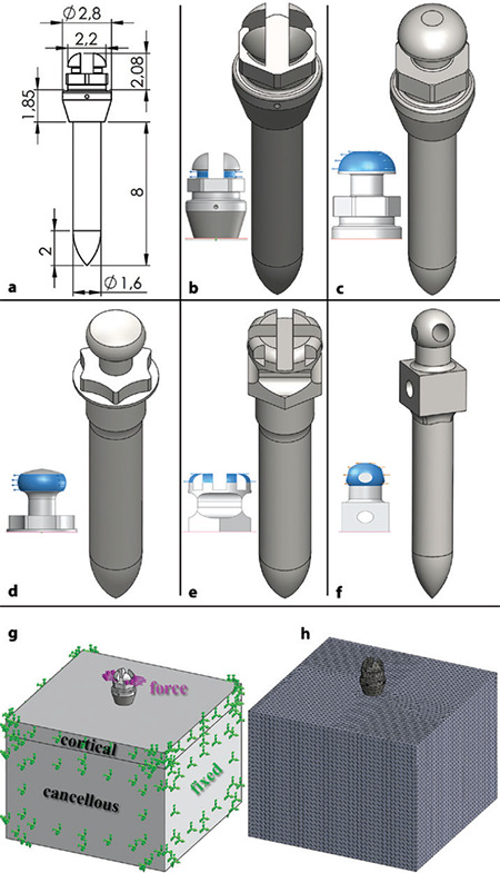
Drawing and FEA properties; a) Miniscrew dimensions, b) Cross head, c) Mushroom head, d) Button head, e) Bracket head, f) Through-hole head, g) Definition of boundary conditions, h) Meshing
Table 1. Material properties.
|
Models |
Miniscrew |
Cortical bone |
Cancellous bone |
|
Elastic modulus (MPa) |
114000 |
14700 |
1500 |
|
Poisson’s ratio |
0.34 |
0.3 |
0.3 |
As boundary conditions, fixed supports were determined in the bone block from all directions except the upper surface (Figure 1g). To create orthodontic force, a horizontal force of 2 N (≈200 gf) was applied to the head of the miniscrew, according to the literature.19 After determining the boundary conditions, the von Mises stress, equivalent strain, and total deformation were calculated using the simulation tool for each model. The Von Mises value is a calculation method used to determine whether the model has undergone plastic deformation or fracture under any loading condition. This value, which is generally used for isotropic and ductile metal materials, is the most crucial parameter to consider in designs.22 Strain is a type of deformation that shows the dimensional or shape change that occurs due to the force applied to the object. The deformation of an object under the influence of internal and external forces or a change from its original shape is called total deformation.23
RESULTS
The values calculated from the analysis of the miniscrews are shown in Table 2. The highest stress was observed in the button head miniscrew, whereas the lowest stress was observed in the bracket head miniscrew. The cross head and mushroom head results were similar; however, the through-hole head type had slightly less stress. The stress distributions of the miniscrews are shown in Figure 2. In the cross head and through-hole head miniscrews, stress was distributed to the thread parts, whereas stress occurred mainly on the collar and head parts in the mushroom head, button head, and bracket head. The highest stress values in the mushroom and button heads were observed in the neck region, while the highest stress in the bracket head occurred in the head region.
Table 2. Analysis results and mesh details for each model.
|
Miniscrew head designs |
Cross |
Mushroom |
Button |
Bracket |
Through-hole |
|
Von mises stress (MPa) |
16.41 |
17.40 |
22.40 |
5.67 |
13.66 |
|
Total deformation (mm) |
1.02E-03 |
7.80E-04 |
8.03E-04 |
4.26E-04 |
1.23E-03 |
|
Strain |
1.66E-04 |
1.36E-04 |
1.45E-04 |
9.87E-05 |
1.45E-04 |
|
Total nodes |
327361 |
334906 |
332820 |
331841 |
317955 |
|
Total elements |
233030 |
238958 |
237563 |
236811 |
226359 |
Figure 2.
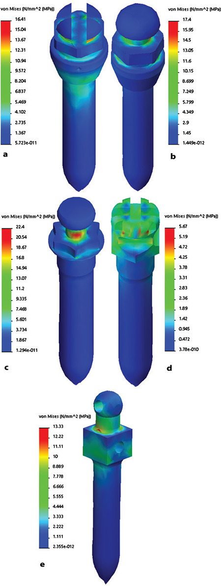
Stress distributions of miniscrew head types isolated from bone block; a) Cross head, b) Mushroom head, c) Button head, d) Bracket head, e) Through-hole head
The stress distribution in the bone block, with the miniscrew hidden is shown in Figure 3. It was observed that more stress occurred on the bone block with the button head compared with the other models. In all models, stress was induced in the upper 2 cm of the bone block, and the highest stress was at the top surface and the intersection with the miniscrew. The maximum von Mises stresses on the bone block were calculated as 4.25 MPa for the cross head, 2.47 MPa for the mushroom head, 3.99 MPa for the button head, 2.49 MPa for the bracket head, and 5.80 MPa for the through-hole head. Deformed models are shown in Figure 4 with a scale factor of approximately 1500. The highest displacement was calculated for the through-hole head, while the lowest was observed for the bracket head. There was little difference between the button head and mushroom head miniscrews according to total deformation. The lowest strain was observed in the bracket head, as with the total deformation. On the other hand, the highest strain was calculated in the cross head miniscrew. In the button head and through-hole head, strain values were determined to be almost the same. The strain results of the models are shown in Figure 5. Mesh convergence analysis was performed by changing the mesh size from 2 mm to 0.5 mm. The results of the mesh convergence analysis for the mushroom head miniscrew are shown in Figure 6. All analyses took less than a minute because the model converged without exceeding the 0.5-mm mesh size and a powerful workstation computer was used. Accordingly, with approximately 239 thousand elements in the 0.5-mm mesh size, the allowable change was decreased below 5%, and iteration was stopped. In addition, because of the analysis performed on all models, there were approximately 230,000 elements in the 0.5 mm mesh size. The node and element numbers of all models are shown in Table 2.
Figure 3.
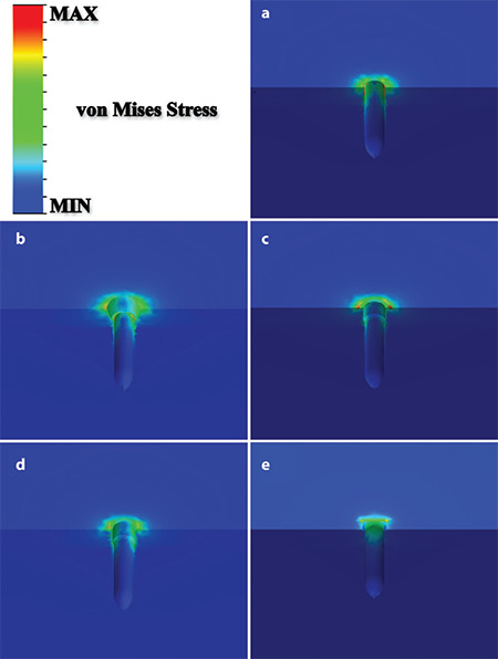
Von Mises stress distributions of the miniscrew cavity; a) Cross head, b) Mushroom head, c) Button head, d) Bracket head, e) Through-hole head
Figure 4.
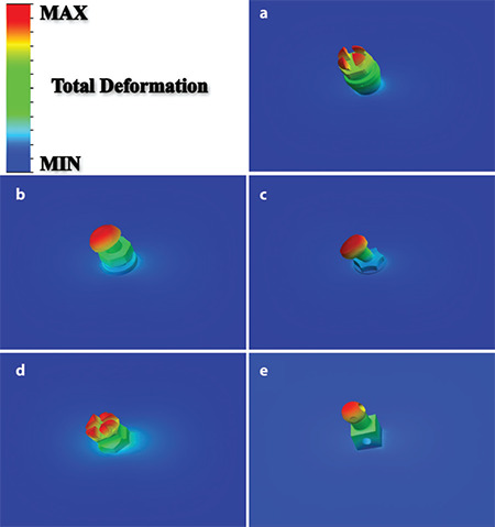
Total deformations of miniscrew head types; a) Cross head, b) Mushroom head, c) Button head, d) Bracket head, e) Through-hole head
Figure 5.
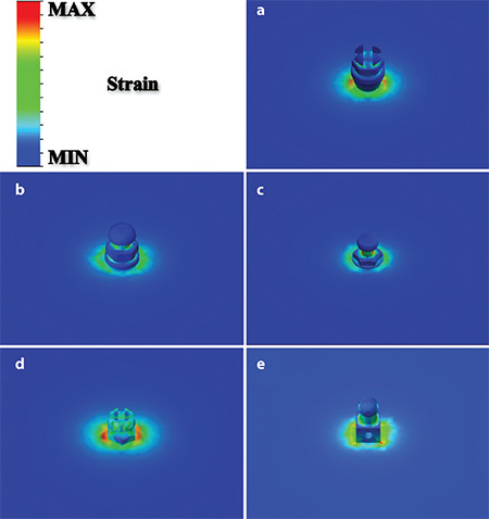
Equivalent strain results of miniscrew head types; a) Cross head, b) Mushroom head, c) Button head, d) Bracket head, e) Through-hole head
Figure 6.
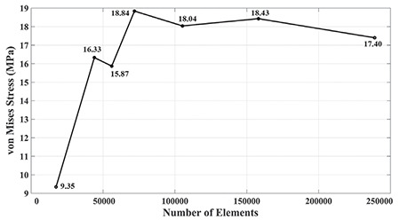
Mesh convergence analysis result for von Mises stress
DISCUSSION
Stress distributions were concentrated on the miniscrew shanks in cross-head and through-head designs, likely due to the different collar designs. It was concluded that collar and neck designs are essential, and their differences directly affect the results. For example, in the button design, the highest stress was observed at the neck due to the smaller diameter design. Therefore, it was determined that there is an inverse relationship between the diameter of the neck and von Mises stress. The lowest neck diameter was 1 mm for the button head, 1.3 mm for the mushroom head, 2.2 mm for the cross head, 2.83 mm for the through-hole head, and 2.6 mm for the bracket. One of the reasons why the bracket design has lower stress than the others is its high neck diameter, and the other is the hexagonal collar design. In addition, the results of von Mises stress in the cross head, mushroom head, and button head, which have a cylindrical neck design, are higher than those of the through-hole, which is the cube design, and the bracket, which is the hexagonal design. Furthermore, although the cross head and bracket head designs are close to each other, the hexagonal neck design reduces the stress value. In the bracket head design, the stress distribution was spread to the miniscrew head and could not extend to the miniscrew tip. In this design, the lowest von Mises stress was calculated as 2.49 MPa in the bone block. Another design with a low von Mises stress value in the bone block is the mushroom head with a stress of 2.47 MPa.
The neck and collar parts have the highest design with a total length of 4.75 mm, preventing the spread of stress to the miniscrew tip. The second-highest length after the mushroom head is the bracket head, with 4.07 mm. In these two designs, the total length of the neck and collar is higher than that of the others, intensifying the stress on the miniscrew head. Furthermore, in cross and bracket head designs, the load is distributed evenly on the surfaces by dividing it into four.
However, the effect of this parameter on stress was limited because both stress values were quite far from each other. On the other hand, the load is applied along a cylindrical surface in other head designs. In these models, the results are close to each other, but because many variables differ, it cannot be concluded that only this parameter affects stress.
However, the applied force to different surfaces caused a change in the region where the stress is concentrated; as a result, the stress in the cross and bracket head designs was concentrated at the corner points and finer trims, which may cause the cross and bracket head designs to become more fragile. Another critical parameter is the distance between the applied load and the bone surface. These distances are 2.81 mm for the cross head, 2.6 mm for the mushroom head, 1.5 mm for the button head, 1.81 mm for the bracket head, and 2.15 mm for the through-hole head. On the other hand, according to Table 2, Table the order of maximum stress values is from largest to smallest as follows; button head, mushroom head, cross head, through-hole head, and bracket head. Although the button head had the lowest distance, it produced the highest stress. Conversely, the cross head had the highest distance, and the average stress value was calculated. Therefore, it cannot be assumed that there is a linear or inverse relationship between the distance of the applied load to the bone surface and the stress results. However, this variable demonstrated that it affected the analysis results.
It started with approximately 20,000 elements in all models and ended with approximately 230,000 elements. These values are high compared to those of other studies and increase the computational time.19 However, a small element size is necessary to converge the results and to reduce the effect of the mesh size change to less than 5%. When the mesh convergence analysis was completed, von Mises stresses similar to those in previous studies were confirmed. For example, Liu et al.13 calculated von Mises stress as approximately 15 MPa by applying a 2 N force to the miniscrew head at a 90º insertion angle. This value is almost the same as the stress value obtained from our cross-head, mushroom-head, and through-hole head designs. Similarly, while they calculated the total deformation as 3 µm, our study determined approximately 1 µm of total deformation in the cross-head and through-hole head designs.
In the study of Perillo et al.,14 von Mises stress was calculated as 5.6 MPa in the bone block when they inserted the miniscrew perpendicularly and applied a 2 N force to the miniscrew head at a force direction of 0º. Our simulation calculated the highest von Mises stress value observed in the bone block as 5.8 MPa. Although the FEA software used in both studies differed, very similar results were observed. In a study by Ye et al.12 comparing thread properties, the von Mises stresses were between 9 and 20 MPa with designs similar to our cross head design. Correspondingly, in our study, the von Mises stress value was 16.41 MPa in the cross head. Overall, the results of our study are very confirmatory for the validation stage of our models, as we obtained results close to those of previous studies.
Study Limitations
There are some limitations to this study. First, the bone structure is not homogeneous and has anisotropic properties that vary throughout. Solving such a complex problem is tricky and requires more running time in FEA. In addition, computed tomography scans of the maxilla or mandible are required to determine the material properties with image processing. Therefore, the bone structure was simplified by using a bone block with defined cortical and cancellous material properties. Although the cortical thickness varies in the literature, it was averaged at 2 mm.13 The effect of bone density on the results is not the focus of this study. In addition, this is not a disadvantage because the same bone block is used in all models. Another limitation is that the thread design was not included in the models to avoid problems in the contact regions and ensure mesh convergence. Because contact meshes in the cavity of the bone block with the miniscrew threads are sometimes not detected, the analysis cannot be performed. This omission does not cause a disadvantage because other dimensions remained consistent across all models, except for the head designs. This study did not investigate the effects of insertion angle, miniscrew dimensions, force direction, and bone properties constant, as these parameters are well-studied in the existing literature. Instead, the focus was on comparing different miniscrew head designs available in the market without modifying their original dimensions and shapes. Future studies could benefit from investigating each of these parameters in detail to develop more stable miniscrews.
CONCLUSION
As a result of the analysis, the lowest stress was obtained in the bracket head, while the highest stress was calculated in the button head. Stress occurred mainly in the collar and head parts in the mushroom head, button head, and bracket head. Consequently, it is concluded that bracket head designs will increase the success ratio in miniscrew treatments. This study was limited to five different miniscrew head designs. In future studies, it is desired to include different head designs and make the model more complex.
Ethics
Ethics Committee Approval: The ethics committee of İzmir Katip Çelebi University decided that this study did not require ethical approval (approval no.: 0488, date: November 18, 2021).
Informed Consent: Not applicable.
Footnotes
Author Contributions: Concept - S.Ç., G.G.K.; Design - S.Ç.; Supervision - Y.İ.; Data Collection and/or Processing - S.Ç., G.G.K.; Analysis and/or Interpretation - S.Ç., G.G.K.; Literature Review - S.Ç., G.G.K.; Writing - S.Ç., G.G.K., Y.İ.
Declaration of Interests: All authors declare that they have no conflict of interest.
Funding: This study was supported by İzmir Katip Çelebi University Scientific Research Council Agency as project number 2023-TDR-FEBE-0005 for Samet Ciklacandir’s doctoral thesis studies.
References
- 1.Baumgaertel S. Temporary skeletal anchorage devices: the case for miniscrews. Am J Orthod Dentofacial Orthop. 2014;145(5):558. doi: 10.1016/j.ajodo.2014.03.009. [DOI] [PubMed] [Google Scholar]
- 2.Emral ME. Assessment the effects of vertical direction control of the dentofacial structures with intrabony implant mechanics. Dissertation. Ankara University; 2012. [Google Scholar]
- 3.Jasoria G, Shamim W, Rathore S, Kalra A, Manchanda M, Jaggi N. Miniscrew implants as temporary anchorage devices in orthodontics: a comprehensive review. J Contemp Dent Pract. 2013;14(5):993–999. doi: 10.5005/jp-journals-10024-1439. [DOI] [PubMed] [Google Scholar]
- 4.Kravitz ND, Kusnoto B. Risks and complications of orthodontic miniscrews. Am J Orthod Dentofacial Orthop. 2007;131(4):S43–S51. doi: 10.1016/j.ajodo.2006.04.027. [DOI] [PubMed] [Google Scholar]
- 5.Liou EJ, Pai BC, Lin JC. Do miniscrews remain stationary under orthodontic forces?. Am J Orthod Dentofacial Orthop. 2004;126(1):42–47. doi: 10.1016/j.ajodo.2003.06.018. [DOI] [PubMed] [Google Scholar]
- 6.Maino BG, Pagin P, Di Blasio A. Success of miniscrews used as anchorage for orthodontic treatment: analysis of different factors. Prog Orthod. 2012;13(3):202–209. doi: 10.1016/j.pio.2012.04.002. [DOI] [PubMed] [Google Scholar]
- 7.Papadopoulos MA, Papageorgiou SN, Zogakis IP. Clinical effectiveness of orthodontic miniscrew implants: a meta-analysis. J Dent Res. 2011;90(8):969–976. doi: 10.1177/0022034511409236. [DOI] [PubMed] [Google Scholar]
- 8.Migliorati M, Benedicenti S, Signori A. Miniscrew design and bone characteristics: an experimental study of primary stability. Am J Orthod Dentofacial Orthop. 2012;142(2):228–234. doi: 10.1016/j.ajodo.2012.03.029. [DOI] [PubMed] [Google Scholar]
- 9.Lin CL, Yu JH, Liu HL, Lin CH, Lin YS. Evaluation of contributions of orthodontic mini-screw design factors based on FE analysis and the Taguchi method. J Biomech. 2010;43(11):2174–2181. doi: 10.1016/j.jbiomech.2010.03.043. [DOI] [PubMed] [Google Scholar]
- 10.Choi SH, Kim SJ, Lee KJ, Sung SJ, Chun YS, Hwang CJ. Stress distributions in peri-miniscrew areas from cylindrical and tapered miniscrews inserted at different angles. Korean J Orthod. 2016;46(4):189–198. doi: 10.4041/kjod.2016.46.4.189. [DOI] [PMC free article] [PubMed] [Google Scholar]
- 11.Ammar HH, Ngan P, Crout RJ, Mucino VH, Mukdadi OM. Three-dimensional modeling and finite element analysis in treatment planning for orthodontic tooth movement. Am J Orthod Dentofacial Orthop. 2011;139(1):e59–e71. doi: 10.1016/j.ajodo.2010.09.020. [DOI] [PubMed] [Google Scholar]
- 12.Ye Y, Yi W, Fan S, et al. Effect of thread depth and thread pitch on the primary stability of miniscrews receiving a torque load.J Orofac Orthop.2021;1-9. doi: 10.1007/s00056-021-00351-w. [DOI] [PubMed] [Google Scholar]
- 13.Liu TC, Chang CH, Wong TY, Liu JK. Finite element analysis of miniscrew implants used for orthodontic anchorage. Am J Orthod Dentofacial Orthop. 2012;141(4):468–76. doi: 10.1016/j.ajodo.2011.11.012. [DOI] [PubMed] [Google Scholar]
- 14.Perillo L, Jamilian A, Shafieyoon A, Karimi H, Cozzani M. Finite element analysis of miniscrew placement in mandibular alveolar bone with varied angulations. Eur J Orthod. 2015;37(1):56–59. doi: 10.1093/ejo/cju006. [DOI] [PubMed] [Google Scholar]
- 15.Herman R, Cope JB. Miniscrew implants: IMTEC mini ortho implants. Semin Orthod. 2005;11(1):32–39. [Google Scholar]
- 16.Melsen B, Verna C. Miniscrew implants: the Aarhus anchorage system. Semin Orthod. 2005;11(1):24–31. [Google Scholar]
- 17.Scribante A, Montasser MA, Radwan ES. Reliability of orthodontic miniscrews: bending and maximum load of different Ti-6Al-4V titanium and stainless steel temporary anchorage devices (TADs). Materials. 2018;11(7):1138. doi: 10.3390/ma11071138. [DOI] [PMC free article] [PubMed] [Google Scholar]
- 18.Alrbata RH, Momani MQ, Al-Tarawneh AM, Ihyasat A. Optimal force magnitude loaded to orthodontic microimplants: A finite element analysis. Angle Orthod. 2016;86(2):221–226. doi: 10.2319/031115-153.1. [DOI] [PMC free article] [PubMed] [Google Scholar]
- 19.Meher AH, Shrivastav SS, Vibhute PJ, Hazarey PV. Deflection and stress distribution around mini-screw implants: A finite element investigation into the effect of cortical bone thickness, force magnitude and direction. J Orthod. 2012;39(4):249–255. doi: 10.1179/1465312512Z.00000000037. [DOI] [PubMed] [Google Scholar]
- 20.Akış H, Doruk C. Dentofacial effects of fixed functional appliances with or without mini screw anchorage in the treatment of class II division I malocclusion: a finite element analysis.Turk J Orthod. ;31:7-12. doi: 10.5152/TurkJOrthod.2018.17026. [DOI] [PMC free article] [PubMed] [Google Scholar]
- 21.Sidhu M, Chugh VK, Dmello K, Mehta A, Chugh A, Tandon P. Evaluation of stress pattern caused by mini-implant in mandibular alveolar bone with different angulations and retraction forces: a three-dimensional finite element study. Turk J Orthod. 2020;33(3):150–156. doi: 10.5152/TurkJOrthod.2020.19109. [DOI] [PMC free article] [PubMed] [Google Scholar]
- 22.Tokuyama-Toda R, Umeki H, Ide S. A New Implantation Method for Orthodontic Anchor Screws: Basic Research for Clinical Applications. Biomedicines. 2023;11(3):665. doi: 10.3390/biomedicines11030665. [DOI] [PMC free article] [PubMed] [Google Scholar]
- 23.Bichu YM, Alwafi A, Liu X. Advances in orthodontic clear aligner materials. Bioact Mater. 2023;22:384–403. doi: 10.1016/j.bioactmat.2022.10.006. [DOI] [PMC free article] [PubMed] [Google Scholar]


