Abstract
Background
C-arm fluoroscopy is the main method assisting surgical reduction and internal fixation of the femoral neck, as traditional anteroposterior and lateral fluoroscopy is insufficient for visualizing the irregular anatomical structure of the femoral neck. We analysed the anatomy of the femoral neck to ascertain the optimal position and angle of the C-arm for adequate visualization of the femoral neck during fluoroscopy.
Methods
The femoral neck was divided into anterior, posterosuperior and posteroinferior surfaces. These surfaces and the coronal plane of the femur formed the anterior surface coronal angle (ACA), posterosuperior surface coronal angle (PSCA) and posteroinferior surface coronal angle (PICA), respectively. Three angles of 32 dried femoral samples were measured. In the aluminium model, steel wires penetrated the femoral neck wall, whereas, in the wire model, three Kirschner wires penetrated the femoral neck wall. The C-arm was rotated 5° for a 0°-180° fluoroscopic view of each curved surface. Each specimen was imaged, totalling 111 frames. The optimal angle for fluoroscopic imaging of each surface was ascertained, and fluoroscopic features of the Kirschner wire penetrating the femoral neck cortex at three different angles on fluoroscopy and anteroposterior and lateral radiographs were observed.
Results
The femoral neck is irregularly shaped and cylindrical, with the anterior surface longer than the posteroinferior surface. The ACA, PSCA and PICA were 31 ± 4.589°, 67.813 ± 5.052° and 168.688 ± 3.206°, respectively. The optimal angles for visualizing the anterior, posterosuperior and posteroinferior surfaces of the steel wire aluminium foil model under fluoroscopy were 30.781 ± 5.464°, 67.969 ± 3.721°, and 167.813 ± 4.319°, respectively. There was no significant difference in the measurements of the corresponding surface coronal angles (P > 0.05). Kirschner wires penetrating the femoral neck wall were difficult to visualize on traditional anteroposterior and lateral films. Increasing the angle to 30°, 70° or 170° for fluoroscopy allowed clear visualization of Kirschner wires penetrating the femoral cortex.
Conclusion
Traditional anteroposterior and lateral fluoroscopic views are insufficient for clear visualization of the true structure of the femoral neck. Additionally, increasing the angle to 30°, 70° or 170° for fluoroscopy allows observation of the fracture reduction quality from the anterior surface, posterosuperior surface and posteroinferior surface of the femoral neck and the damage to the corresponding cortical bone caused by internal fixation.
Level of evidence
Level II.
Keywords: Femoral neck, Fluoroscopy, Anatomy, C-arm, X-ray, Femoral neck section, Cadaver
Introduction
Closed reduction and internal fixation are more common surgical techniques for treating femoral neck fractures in hospitals. In clinical practice, C-arm X-ray is frequently used to obtain standard AP and lateral views of the femoral neck for intraoperative fluoroscopic evaluation to assess the quality of fracture reduction and screw placement [1–3]. Because of the irregular and cylindrical shape of the femoral neck, its anatomy cannot be clearly visualized on standard femoral neck AP and lateral views [4, 5]. G-arm X-ray is a simpler method but does not provide clear images. Intraoperative CT may be sufficient for imaging the femoral neck and guiding screw placement. The complexity and high costs of some imaging techniques limit their widespread use in primary hospitals and therefore their use in the fixation of femoral neck fractures [5, 6].
According to several studies [7–10], The screw went through the femoral neck could not be spotted by the C-arm X-ray, which are primarily fixed with screws positioned in an inverted triangle in the posterosuperior quadrants of the femoral neck using the in-out-in technique. Zhang YQ [11] proposed that screws placed in the posterosuperior and anteroinferior quadrants of the femoral neck are likely to penetrate the femoral neck cortex. Continuous X-ray from multiple angles is more reliable for intraoperative monitoring [7, 12, 13], but too many fluoroscopies expose patients and doctors to excessive amounts of radiation. There is no consensus on the optimal position of the C-arm or optimal angle for intraoperative fluoroscopy.
To find the optimal angles for intraoperative fluoroscopy, in this study, we used a combination of steel wire and aluminium foil paper to mark different anatomical positions of the femoral neck wall and simulated intraoperative fluoroscopy using a C-arm. The characteristics of the femoral neck on images obtained at different angles were analysed.
Materials and methods
Specimens and femoral neck section anatomy
Thirty-three dry, intact femoral specimens from 17 adults (13 men and 4 women; average age 58.5 years, range, 49 to 72y) were obtained from the Department of Anatomy, County Health School. Written consent was obtained from the people before death or from the next of kin to use the specimens in this study. This study was approved by the ethics committee of our hospital. No visible deformities or defects in the distal or proximal femurs were observed.
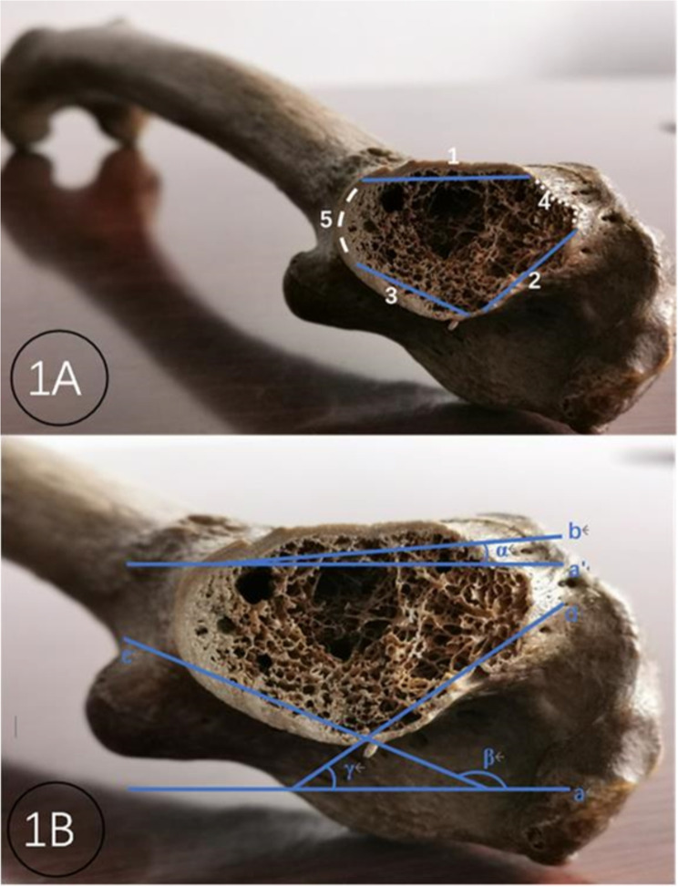
One unpaired dry femoral specimen was cut perpendicular to the long axis of the femoral neck in the middle of the femoral neck to expose the femoral neck section. The cross section of the femoral neck is approximately an ellipse formed by multiple curved surfaces, consisting of shorter upper and lower edges and longer anterior and posterior walls. The anterior wall is longer and less radian, so it can be seen as a surface, and it is defined as the anterior surface. The posterior wall is semicircular and has a larger arc, which can be regarded as two surfaces with small arcs and are defined as the posterosuperior surface and the posteroinferior surface separately (Fig. 1A).
Fig. 1.
Schematic diagram of a femoral neck section and three curved surface coronal angles. Note: 1 Structural view of the femoral neck section: 1 anterior curved surface, 2 posterosuperior curved surfaces, 3 posteroinferior curved surfaces, 4 upper edges, and 5 lower edges. 1B Construction of three curved surfaces coronal to the femoral neck: a and a’ femoral coronal plane, b arc of the anterior curved surface, c arc of the posterosuperior curved surface, d arc of the posteroinferior curved surface, ∠α anterior curved surface coronal angle, ∠β posteroinferior curved surface coronal angle, and ∠γ posterosuperior curved surface coronal angle
Definition of the surface coronal angle
The angle between the three surfaces of the femoral neck wall and the coronal plane of the femur, which is determined by the nadir of the greater trochanter and the medial and lateral condyles of the femur, was defined as the surface coronal angle. For convenient description and measurement, the femoral neck section in the middle of the femoral neck was taken. The two ends of each surface are connected to form the chord of the surface. The angle formed by the chord and the coronal plane of the femur is defined as the surface coronal angle. In this way, the femoral neck wall curved surface and femoral coronal plane constitute three surface coronal angles: the anterior surface coronal angle (ACA), posterosuperior surface coronal angle (PSCA) and posteroinferior surface coronal angle (PICA) (Fig. 1B).
Parameters of the femoral neck section and the surface coronal angles
There were 32 dried femur samples, 16 from each side. The circumference of the femoral neck section, the length of the upper and lower edges, the anterior surface, the posterosuperior surface and the posteroinferior surface were measured with a tape measure. The dried femur is laid on the countertop, which is in contact with the nadir of the greater trochanter and the medial and lateral condyles of the femur. A Kirschner wire was applied to attach each of the three surfaces of the femoral neck wall. When the Kirschner wire reached maximum contact with the corresponding surface, the Kirschner wire was fixed, and the femoral specimen was removed. The angle between the Kirschner wire and the worktable was measured directly with a protractor, and the protractor reading was used as the data of the corresponding surface coronal angle size.
Model of the femoral neck wall with steel wire and aluminium foil attached
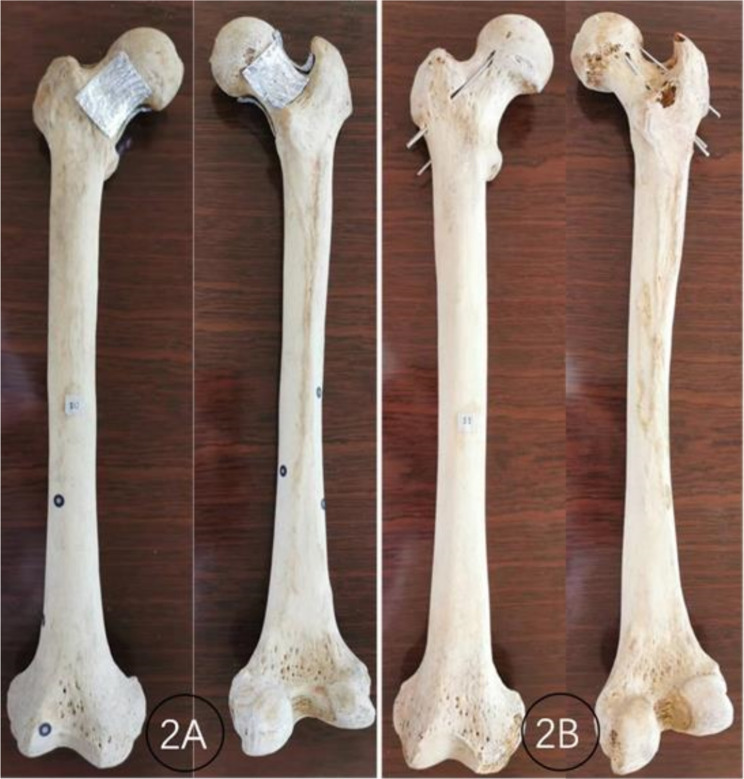
The aluminium foil paper (original thickness of 10 nm, folded thickness of 1.28 mm) was cut into the corresponding sizes of the anterior surface, posterosuperior surface and posteroinferior surface of the femoral neck wall; by closely attaching to the surface, it was shaped into the corresponding structure of each surface. The aluminium foil paper and wind steel wire with a diameter of 0.5 mm were removed from the surface with a spacing of 2–3 mm. Then, it was attached to the femoral neck wall with double-sided tape to make a steel wire wind aluminium foil model (Fig. 2A). The fluoroscopic image of the steel wire from the aluminium foil paper represents the image characteristics of a certain curved surface.
Fig. 2.
Model of the femoral neck wall attached to steel wire wind aluminium foil (2 A) and a model of three Kirschner wires perforating the femoral neck wall
Multiangle radiography of the steel wire and aluminium foil models
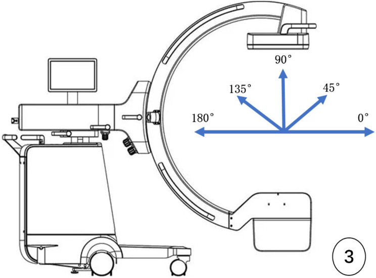
Philips BV Endura X-ray machine (Netherlands), C-arm opening diameter 77 cm, arc depth 61 cm, maximum rotation angle 115°. The C-arm X-ray machine was operated by a senior orthopaedic surgeon with more than 500 operations. The machine was placed on the projection position such that the C-arm was perpendicular to the long axis of the femoral neck and approximately 45° from the femoral shaft (adjusted according to the neck–shaft angle of the femoral neck). With the midpoint of the femoral neck as the centre point of the projection, it is defined as the 0° position when the X-ray generator is away from the main machine; in contrast, when the generator is close to the main machine, it is 180° (Fig. 3).
Fig. 3.
Schematic diagram of the intraoperative C-arm X-ray fluoroscopic angle
Three pieces of steel wire and aluminium foil paper were placed in turn and closely attached to the corresponding surface of the femoral neck. After the femoral specimen was fixed on the worktable, the projecting centerline was adjusted, and the C-shaped arm was rotated to obtain X-ray images of the femoral neck. The C-arm was set to rotate at 5° intervals between 0° and 180°, and 37 fluoroscopic images were obtained from each steel wire wind aluminium foil model. When the image size of the steel wire wind aluminium foil is changed to a minimum, the angle between the worktable and the projecting centerline is considered the appropriate fluoroscopic angle of the corresponding curved surface of the femoral neck, and its value is recorded. This image is also referred to as the tangent image of a certain curved surface.
Model of three Kirschner wires perforating the femoral neck wall
One femoral specimen that completed the aforementioned measurement experiment was taken. Three Kirschner wires with a diameter of 2.5/2.0/1.5 mm were implanted from the femoral lateral wall through the femoral neck to the femoral head, and the three Kirschner wires pierced the anterior surface, posterosuperior surface and posteroinferior surface, respectively. Thus, the model of three Kirschner wires piercing the femoral neck wall was completed (Fig. 2B). In accordance with the above fluoroscopy method, the C-arm was rotated every 5° to ensure that the fluoroscopic angle ranged from 0° to 180°. The Kirschner wire penetrating the femoral neck wall on the image was observed. The five fluoroscopy angles used were as follows: traditional posterior–anterior and lateral views and three appropriate fluoroscopic angles of the corresponding curved surface of the femoral neck obtained in the aforementioned experiment.
Statistical analysis
Continuous variables such as the circumference of the femoral neck section; the length of the upper and lower edges; the anterior surface, posterosuperior surface and posteroinferior surface; the surface coronal angle (ACA, PSCA and PICA); and the appropriate fluoroscopic angle are expressed as the mean and standard deviation (SD). The statistical analyses were performed via Microsoft Excel, and the statistical tests were performed via Student’s t test. A P value < 0.05 indicated statistical significance.
Results
The anatomy and parameters of femoral neck sections
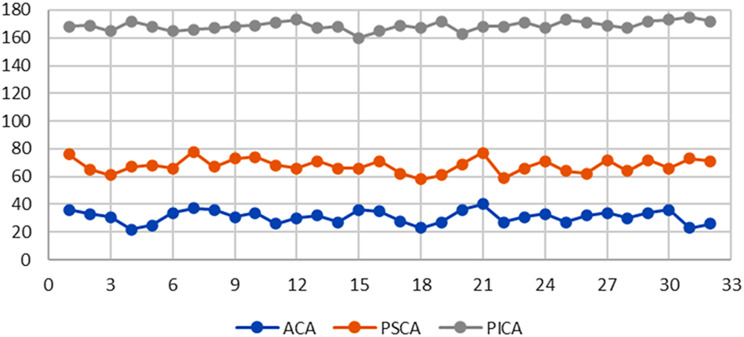
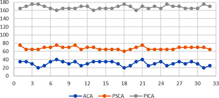
The femoral neck is irregularly cylindrical in macroscopic view. The femoral neck section is an irregular ellipse composed of upper and lower edges and multiple curved surfaces. The circumference of the femoral neck section measured in the middle of the femoral neck was 9.303 ± 0.521 cm. The measured data of the lengths of the upper and lower edges, the anterior surface, posterosuperior surfaces and the posteroinferior surface are shown in Table 1. The upper margin of the femoral neck is significantly shorter than the lower margin, the anterior surface is significantly longer than the posterosuperior and posteroinferior surfaces, and the posterosuperior surface is significantly longer than the posteroinferior surface. In addition, the data distributions of the surface coronal angles (ACA, PSCA and PICA) of the 32 femoral necks are shown in Table 2. The measured angles of the ACA, PSCA and PICA were 31 ± 4.59°, 67.81 ± 5.05° and 168.69 ± 3.21°, respectively.
Table 1.
Anatomy parameters of femoral neck sections
| Upper edge | Lower edge | ACA | PSCA | PICA | |
|---|---|---|---|---|---|
| Data(cm) | 0.616 ± 0.170 | 1.291 ± 0.142 | 3.003 ± 0.172 | 2.05 ± 0.125 | 2.344 ± 0.143 |
| P value | T=-17.841, P<0.01 | T*=37.534, T#=31.409, T¥=-14.297, P<0.01 | |||
Notes ACA anterior surface coronal angle; PSCA posterosuperior surface coronal angle; PICA posteroinferior surface coronal angle. T* comparison of the ACA and PSCA; T# comparison of the ACA and PICA; T¥ comparison of the PSCA and PICA
Table 2.
Measured data of three surface coronal angles of the femoral neck (N = 32)
Imaging characteristics and appropriate fluoroscopic angle of the steel wire and aluminium foil models
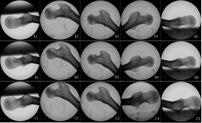
The image of specimen No. 15 is taken as an example (Fig. 4). On the anterior curved surface, the steel wire and aluminium foil covered half of the femoral neck at 0°, and it became minimal when the C-shaped arm was rotated to 35°. After that, the covered area gradually increased with increasing fluoroscopic angle. The majority of the femur was covered at 90°, and the maximum area reached 125°, after which it decreased. The steel wire foil was completely contained by the femoral neck at 110° to 145°. On the posterosuperior curved surface, the steel wire aluminium foil covered half of the femoral neck at 0°, and the development was minimal at 65°. With increasing fluoroscopic angle, the development area gradually increased, covering approximately 1/3 of the femoral neck at 90°, reaching the maximum area at 150°, and gradually decreased to cover approximately half of the femoral neck at 180°, that is, the 0° image. The posterosuperior steel wire foil was completely contained by the femoral neck at 110° ~ 175°. On the posteroinferior curved surface, the view of the steel wire aluminium foil was small at 0°, covering only 1/3 of the femoral neck. The angle of view increased with increasing fluoroscopic angle and reached a maximum at 75°. With increasing fluoroscopic angle, the angle gradually decreased, covering the majority of the femoral neck at 90°, and the smallest view was at 165°. The angle was then gradually increased to cover 1/3 of the femoral neck at 180°, which was basically consistent with the 0° view. The posteroinferior steel wire foil was completely contained by the femoral neck at 50° ~ 90°.
Fig. 4.
Fluoroscopic image of three curved surfaces of the femoral neck wall attached to the steel wire wind aluminium foil model (specimen No. 15): A1, 0° position; A2, 35° position; A3, 90° position; A4, 125° position; A5, 180° position; B1, 0° position; B2, 70° position; B3, 90° position; B4, 150° position; B5, 180° position; C1, 0° position; C2, 75° position; C3, 90° position; C4, 165° position; and C5, 180° position
The position angle of the C-shaped arm is defined as the appropriate fluoroscopic angle of its curve surface when the steel foil is minimized. The data size distribution is shown in Table 3. The appropriate fluoroscopic angles of the ACA, PSCA and PICA were 30.781 ± 5.464°, 67.969 ± 3.721° and 167.813 ± 4.319°, respectively. To facilitate intraoperative application, 30°, 70° and 170° angles were taken as the intraoperative fluoroscopic angles. The surface coronal angle data of each curved surface obtained via direct measurement of the 32 bare bones were basically consistent with the appropriate fluoroscopic angle obtained via perspective image measurement (Table 4), and there was no significant difference.
Table 3.
Appropriate fluoroscopic angle data for the femoral neck (N = 32)
Table 4.
Comparison of appropriate fluoroscopic angles and surface coronal angles
| ACA | PSCA | PSIA | |
|---|---|---|---|
| Appropriate fluoroscopic angle | 30.781 ± 5.464 | 67.969 ± 3.721 | 167.813 ± 4.319 |
| Surface coronal angle | 31 ± 4.589 | 67.813 ± 5.052 | 168.688 ± 3.206 |
| T and P values | T = 0.5143, P = 0.6107 | T=-0.2615, P = 0.7955 | T = 1.2585, P = 0.2176 |
Notes ACA anterior surface coronal angle; PSCA posterosuperior surface coronal angle; PICA posteroinferior surface coronal angle
Model of three Kirschner wires perforating the femoral neck wall
The model revealed that three Kirschner wires of different diameters penetrated the femoral neck wall against the anterior surface, posterosuperior surface and posteroinferior surface of the femoral neck (Fig. 2B). Standard lateral view revealed that the anterior and posteroinferior curved Kirschner wires were suspected to penetrate the cortex, and there was no clear boundary with the femoral neck bone. The posterosuperior curved Kirschner wires were contained in the femoral neck. On the 30° image, the anterior curved Kirschner wire completely penetrated the femoral neck and was clearly located outside the anterior cortex, and the posterosuperior and posteroinferior curved Kirschner wires were located inside the femoral neck. In the 70° view, the posterosuperior curved Kirschner wire completely penetrated the posterior cortex of the femoral neck, and the anterior and posteroinferior curved Kirschner wires were contained in the femoral neck.
Standard anteroposterior radiography (90° position) revealed that the Kirschner wire partially penetrated the femoral neck cortex on the posterosuperior surface, but the Kirschner wire did not penetrate the anterior and posteroinferior curved surface cortex. At 170°, the posteroinferior Kirschner wire completely penetrated the femoral neck cortex, and the anterior and posterosuperior curved surface Kirschner wires were located inside the femoral neck (Fig. 5).
Fig. 5.
Fluoroscopic image of three Kirschner wires perforating the femoral neck wall model: the diameters of the Kirschner wires on the anterior, posteroinferior and posterosuperior curved surfaces were 2 mm, 1.5 mm and 1 mm, respectively. A: 30°, B: 70°, C: 90°, D: 170°, E: 180°
Discussion
The anatomical structure of the femoral neck cannot be completely shown by traditional anteroposterior and lateral fluoroscopic images
This technique has decisive significance for the prognosis of femoral neck fractures because of the good quality of fracture reduction and accurate implantation of internal fixation. These procedures need to be performed under intraoperative X-ray monitoring. At present, the precise position of screw implantation is commonly monitored under anteroposterior and lateral images of the femoral neck, and the quality of reduction is judged by observing the Garden index and Lowell curve [1, 2]. Cai LY [3] reported that rotation of the femoral neck fracture ending at 30° could not be detected under traditional anteroposterior and lateral X-ray images through cadaveric bone tests unless the rotation reached more than 40°. In previous studies of internal fixation in the femoral neck with inverted triangle screws, several scholars [7–11] reported that the posterosuperior screw easily penetrated the femoral neck cortex. When the screw diameter above the piriformis fossa reaches 6.5 mm, the penetration rate reaches 70% [13]. Aibinder WR et al. reported that screws can easily penetrate the anteroinferior and posterosuperior parts of the femoral neck but cannot be detected via routine intraoperative X-ray monitoring. In addition to traditional anteroposterior and lateral fluoroscopy, multiangle projection should be used to detect the screws that may pass through the femoral head or neck during the operation to correct the position of the screw in time [7, 14]. However, the details of the specific fluoroscopic position and angle have not been proposed. Chen SY et al. explored a good angle and position of intraoperative C-arm X-ray fluoroscopy, which was mainly used for accurate implantation of the head nail of the proximal femoral intramedullary nail [15, 16]. This technique was helpful for adjusting the anteversion angle of the femoral neck for internal fixation but could not find the screw penetrating the femoral neck cortex.
Our model of three Kirschner wires perforating the femoral neck wall revealed that the anterior and posteroinferior surface Kirschner wires could not be detected via standard anteroposterior radiography, and whether the posterosuperior surface Kirschner wire penetrated the femoral neck was not certain. Only when the position of the posterosuperior Kirschner wire was superior could it be identified. On standard lateral radiographs, the posterosuperior Kirschner wire penetrating the femoral neck cortex could not be found, and whether the anterior and posteroinferior surface Kirschner wires penetrate the femoral neck cortex is sometimes unclear. This can be detected only when the screw penetrates out of the femoral neck cortex in the superior position.
The femoral neck is an irregular cylindrical structure composed of multiple curved surfaces and not a standard cylindrical shape. Anatomical parameters such as the femoral collodiaphyseal angle, anteversion angle and femoral neck torsion angle of the proximal femur indicate an irregular three-dimensional anatomical structure of the proximal femur [4, 17]. To explore the three-dimensional anatomical structure of the irregular femoral neck via two-dimensional imaging of anteroposterior and lateral radiographs, an observation blind area is needed. Studies have shown that blind areas exist mainly in the periphery of the femoral head and the posterosuperior and anteroinferior quadrants of the femoral neck [4, 13, 18, 19]. According to our anatomical study, the femoral neck section is composed of three large, curved surfaces anteriorly and posteriorly and the upper and lower edges. The upper and lower edges are short and can be visualized in the anteroposterior fluoroscopic view. As the anterior and posterior surfaces are long and irregular and the cortical thickness is inconsistent, a lateral fluoroscopic image of the femoral neck cannot accurately show all the full surfaces. According to the maximum radian (tangent line) of each surface, the anterior and posterior surfaces of the femoral neck were divided into three surfaces, which were named the anterior surface, posterosuperior surface and posteroinferior surface. The angle formed by the chord of each surface and the coronal plane of the femur is defined as the surface coronal angle of the curved surface, which is called the anterior surface coronal angle (ACA), posterosuperior surface coronal angle (PSCA) and posteroinferior surface coronal angle (PICA), respectively. In theory, angle size data can be used as the intraoperative appropriate fluoroscopic angle of a curved surface. To further test its scientific characteristics, we carried out an experimental demonstration of the steel wire aluminium foil model and the Kirschner wires perforating the femoral neck wall model.
Three fluoroscopy angles were used as effective supplements to traditional anteroposterior and lateral fluoroscopy of the femoral neck
The femoral neck cortex is thickest at the lower margin, followed by the anterior and posteroinferior surfaces, and the posterosuperior surfaces are thinnest. To distinguish and display the three surfaces, we folded the aluminium foil paper to the corresponding thickness and woven steel wire on its surface. Therefore, it can be partially penetrated by X-ray and shows the difference between it and the femoral neck bone. The samples were cut into corresponding sizes and attached to the three femoral neck surfaces to represent the three curved cortices. When the image of steel wire foil under fluoroscopy is the smallest, it can be used as the appropriate fluoroscopic angle of the surface. The appropriate fluoroscopic angles of the samples in this study were 30° for the anterior surface, 70° for the posterosuperior surface, and 170° for the posteroinferior surface, which were consistent with the surface coronal angles of the measured data of the samples. The quality of cortical reduction at the fracture end of the femoral neck surface can be determined on the basis of fluoroscopic images of the anterior, posterosuperior and anteroinferior surfaces.
In the test of Kirschner wire penetration out of the femoral neck, three curved surface Kirschner wires could be partially found penetrating the femoral neck cortex on traditional anteroposterior and lateral radiographs, but the full penetration of the Kirschner wire could not be spotted. This means that it could not be completely detected in traditional anteroposterior and lateral radiographs when the Kirschner wires slightly penetrated the femoral neck cortex. When the appropriate fluoroscopic angle of the three surfaces was added, the anterior Kirschner wire was visible at the 30° position, the posterosuperior Kirschner wire was visible at the 70° position, and the posteroinferior Kirschner wire was visible at the 170° position, penetrating the femoral neck cortex completely. In clinical practice, when the implant is suspected to penetrate the femoral neck cortex, the corresponding fluoroscopic angle can be added to ensure that the penetrating surface of the femoral neck cortex can be detected by fluoroscopy to make timely adjustments.
Limitations of this study
In accordance with the anatomical characteristics of the femoral neck, this study explored the addition of an appropriate C-arm X-ray fluoroscopic angle to visualize the overall proximal femoral structure. Although the dried femur samples used in this study were ordinary and without deformities, which could represent the characteristics of the patient’s femur during surgery, there was no soft tissue attachment, and the position of the patient on the traction bed could not be completely simulated. When the study results are used for intraoperative reference, the influence on the image of the immediate intraoperative position should be considered. In addition, the sample used in this study was the femoral neck with a normal anatomical structure, so the position of the femoral neck and the position of internal fixation after fracture reduction can be effectively evaluated in clinical practice. However, it is difficult to evaluate the femoral neck anatomy effectively for fracture displacement and deformity. It is necessary to find specific X-ray anatomical markers of the femoral head and trochanter to determine the relative position of the fracture and deformity as a further expansion and improvement of this study.
Conclusion
In conclusion, the femoral neck is an irregular cylindrical shape composed of an anterior surface and posterosuperior and posteroinferior surfaces, with upper and lower edges. The overall structure of traditional anteroposterior and lateral fluoroscopy during an operation cannot be accurately displayed. Additionally, 30°, 70° and 170° fluoroscopic angles can be used to observe the fracture reduction quality of each surface of the femoral neck accurately, and the corresponding cortical injury caused by internal fixation can be clearly detected.
Acknowledgements
Not applicable.
Author contributions
QL Zhu Responsible for research design and implementation, XP Yu Complete data collection and statistical analysis, Jun Ma, Fang Lin, Yun-yun Chen, Wen-bin Ruan participated in specimen measurement and experimental process.
Funding
Not applicable.
Data availability
The datasets used and/or analyzed during the current study are available from the corresponding author on reasonable request.
Declarations
Consent for publication
Not applicable.
Informed consent
dry femoral specimens were from donations by the Department of Anatomy, County Health School. Informed written consent was obtained from the people before death or from next of kin to use the specimens in this study.
Competing interests
The authors declare no competing interests.
Footnotes
Publisher’s note
Springer Nature remains neutral with regard to jurisdictional claims in published maps and institutional affiliations.
References
- 1.Garden RS. Malreduction and avascular necrosis in subcapital fractures of the femur. J Bone Joint Surg Br. 1971;53:183–97. [PubMed]
- 2.Agar A, Utkan A. The Effect of Anatomical reduction on functional outcomes in femoral Neck fracture: a Novel Modified Garden Index. Cureus. 2021;13(11):e19863. [DOI] [PMC free article] [PubMed] [Google Scholar]
- 3.Cai LY, Li WJ, Zheng WH, Wang JS, Guo XS. Changes in radiological parameters during reduction of femoral neck fractures: a radiographic evaluation of cadavers. Injury. 2021;52(10):2827–34. [DOI] [PubMed] [Google Scholar]
- 4.Zhu QL, Shi BG, Xu B, Yuan JF. Obtuse triangle screw configuration for optimal internal fixation of femoral neck fracture-an anatomical analysis. Hip Int. 2018;29(1):72–6. [DOI] [PubMed] [Google Scholar]
- 5.He M, Han W, Zhao CP, Su YG, Zhou L, Wu XB, Wang JQ. Evaluation of a Bi-planar Robot Navigation System for Insertion of Cannulated Screws in femoral Neck fractures. Orthop Surg. 2019;11(3):373–9. [DOI] [PMC free article] [PubMed] [Google Scholar]
- 6.Moulin B, Tselikas L, De Baere T, Varin F, Abed A, Debays L, Bardoulat C, Hakime A, Teriitehau C, Deschamps F, Gravel G. CT guidance assisted by electromagnetic navigation system for percutaneous fixation by internal cemented screws (FICS). Eur Radiol. 2020;30(2):943–9. [DOI] [PubMed] [Google Scholar]
- 7.Aibinder WR, Yuan BJ, Cross WW III, Parry JA. Sequential fluoroscopic rollover images reliably identify in-out-in posterosuperior screws during percutaneous fixation of femoral neck fractures. Eur J Orthop Surg Traumatol. 2020;30(6):1061–5. [DOI] [PubMed] [Google Scholar]
- 8.Trikha V, Kumar A, Mittal S, Passey J, Chouhan D, Dubey S. Risk of bony violation with standard triple screw configurations for fixation of femoral neck fractures: a preliminary computed tomography based analysis. J Clin Orthop Trauma. 2020;11(4):s546–552. [DOI] [PMC free article] [PubMed] [Google Scholar]
- 9.Hofmann JC, Kellam J, Kumaravel M, Clark K, Routt MLC, Gary JL. Is the cranial and posterior screw of the inverted triangle configuration for femoral neck fractures safe? J Orthop Trauma. 2019;33(7):331–4. [DOI] [PubMed] [Google Scholar]
- 10.Zhang J, Tang X. The application of the 150° oblique tangential fluoroscopic view to detect the posterosuperior femoral neck screw in-out-in intraoperatively. Sci Rep. 2022;12(1):12790. [DOI] [PMC free article] [PubMed] [Google Scholar]
- 11.Zhang YQ, Chang SM, Huang YG, Wang X. The femoral neck safe zone: a radiographic simulation study to prevent cortical perforation with multiple screw insertion. J Orthop Trauma. 2015;29(5):e178–182. [DOI] [PubMed] [Google Scholar]
- 12.Zhang L, Lin GM, Yang GJ, Ghamor-Amegavi EP, Liu M, Pan ZP, Chen SX. Multiple Radiographic Projections in Detecting Intra-articular Screw Penetration During Fixation of Femoral Neck Fractures. Orthopedics. 2014;37(10):e885-891. [DOI] [PubMed]
- 13.Adams JDJ, Walker JB, Loeffler M. Avoid the In-Out-In posterosuperior femoral neck screw: the use of the piriformis fossa radiographic landmark. J Orthop Trauma. 2022;36(5):224–7. [DOI] [PubMed] [Google Scholar]
- 14.Kumar A, Jameel J, Qureshi OA, Kumar M, Haider Y, Das S. Modified radiographic views to prevent the anterosuperior and posterosuperior bony violation during screw fixation of femoral neck fractures. Eur J Orthop Surg Traumatol. 2021;31(3):459–64. [DOI] [PubMed] [Google Scholar]
- 15.Chen SY, Chang SM, Tuladhar R, Wei Z, Xiong WF, Hu SJ, Du SC. A new fluoroscopic view for evaluation of anteromedial cortex reduction quality during cephalomedullary nailing for intertrochanteric femur fractures: the 30 degrees oblique tangential projection. BMC Musculoskelet Disord. 2020;21(1):719–26. [DOI] [PMC free article] [PubMed] [Google Scholar]
- 16.Pisoudeh K, Elahifar O, Alimoghadam S, Eslami A. Trans-table intraoperative fluoroscopic technique for obtaining a true lateral view of the proximal femur in the lateral decubitus position. Arch Bone Jt Surg. 2023;11(8):531–4. [DOI] [PMC free article] [PubMed] [Google Scholar]
- 17.Shitova AD, Kovaleva ON, Olsufieva AV, Gadzhimuradova IA, Zubkov DD, Kniazev MO, Zharikova TS, Zharikov YO. Risk modeling of femoral neck fracture based on geometric parameters of the proximal epiphysis. World J Orthop. 2022;13(8):733–743. [DOI] [PMC free article] [PubMed]
- 18.Yuan BJ, Shamaa MT, Aibinder WR, Parry JA, Cross WW, Barlow JD, Sems SA. High incidence of in-out-in posterosuperior screws after cannulated screw fixationof femoral neck fractures. Eur J Orthop Surg Traumatol. 2020;30(8):1417–20. [DOI] [PubMed]
- 19.Kumar A, Kumar M, Arora R, Passey J, Das S, Chauhan S. Radiographic quantification of safe zones for screw placement in the femoral neck: a computed tomography-based analysis. J Orthop Trauma. 2021;35(3):136–42. [DOI] [PubMed] [Google Scholar]
Associated Data
This section collects any data citations, data availability statements, or supplementary materials included in this article.
Data Availability Statement
The datasets used and/or analyzed during the current study are available from the corresponding author on reasonable request.


