

Abstract
In order to implement multiple electromagnetic (EM) wave front control, a reconfigurable multifunctional metasurface (RMM) has been investigated in this paper. It can meet the requirements for 6G communication systems. Considering the full-space working modes simultaneously, both reflection and transmission modes, the flexible transmission-reflection-integrated RMM with p-i-n diodes and anisotropic structures is proposed. By introducing a 45°-inclined H-shaped AS and grating-like micro-structure, the polarization conversion of linear to circular polarization (LP-to-CP) is achieved with good angular stability, in the transmission mode from top to bottom. Meanwhile, reflection beam patterns can be tuned by switching four p-i-n diodes to achieve a 1-bit reflection phase, which are embedded in the bottom of unit cells. To demonstrate the multiple reconfigurable abilities of RMMs to regulate EM waves, the RMMs working in polarization conversion mode, transmitted mode, reflected mode, and transmission-reflection-integrated mode are designed and simulated. Furthermore, by encoding two proper reflection sequences with elements, reflection beam patterns with two beams and four beams can be achieved, respectively. The simulation results are consistent with the theoretical method. The suggested metasurface is helpful for radar and wireless communications because of its compact size, simple construction, angular stability, and multi-functionality.
Keywords: metasurface, multifunctional, reconfigurable, transmission-reflection integrated, full-space
1. Introduction
A metasurface (MS) is a surface with periodic or aperiodic structures, consisting of subwavelength elements, which possess the unique ability to control the amplitude [1,2], phase [2,3], and polarization states [4,5] of incident electromagnetic (EM) waves. They have some advantages such as a lower profile, low insertion loss, and easy integration with other circuits [6,7]. With the help of innovative techniques for modulating electromagnetic waves and a variety of useful applications, including diffusion, anomalous reflection and refraction [8,9], radar cross-section reduction [10,11], beam scanning [12,13,14], focusing [15,16], polarization conversion [17,18,19], and holography [20], researchers have flexibly designed MSs based on the generalized Snell’s law [21]. Nonetheless, passive unit cells make up the majority of these designs. Their functions are set once they are produced, and they can only be used for a limited number of pre-planned uses. As a result, they are unable to meet the growing needs for communications and multifunctional devices.
Compared with passive MSs whose functions are fixed [22], reconfigurable MSs possess a stronger superiority [23,24]. Versatile features are expected because of their dynamic status changes. Therefore, the reconfigurable multifunctional metasurfaces (RMMs) can be controlled by electrical, optical, mechanical, and thermal means, which have been developed. These RMMs control EM waves from microwave to terahertz bands; furthermore, they are useful in a variety of applications, including antenna design [25], polarization conversion [26,27,28,29], and beam steering [30,31,32]. In the meantime, tunable MSs have been designed using functional materials such as liquid crystals [33], graphene [34,35], and vanadium dioxide (VO2) [36]. For example, using the insulator-to-metal transition feature of VO2, the researchers in [36] created a switchable MS that can accomplish broadband absorption and reflection. However, these RMMs mostly operate in either the transmission or reflection mode to regulate EM waves in half-space, and the other space is unutilized. Nonetheless, RMMs in full-space will possess a wider prospect, particularly with the growing demands for highly integrated and more powerful devices in 6G communication systems.
Driven by the imperative demand for both design integration and miniaturization for 6G applications, based on the earlier research in [37], we further present a flexible transmission-reflection-integrated RMM with p-i-n diodes and an anisotropic structure (AS), which can convert the x-polarized EM waves to circular polarization (CP) in the transmission mode from top to bottom, and control reflection beam patterns of the y-polarized EM waves in the reflection mode from bottom to top. The suggested unit cell for the MS is made up of five delicately designed metal patterns separated by four substrate layers. The upper three metal patterns complete the polarization conversion of linear-to-right hand circular polarization (LP-to-CP). By integrating four p-i-n diodes into metal layer 5, 1-bit tunable reflection phases are realized, which can control the y-polarized EM wave reflection patterns from bottom to top. To verify its adjustable property, a 13 × 13 array is designed, which can reflect beam patterns with two beams and four beams in reflection mode through the modulation of the switchable status on p-i-n diodes. Unlike previous research, our designs provide a feasible way of realizing adjustable multifunctional MSs operating in full space, which possess good angular stability and can result in many fascinating applications in wireless communications and radar.
2. Metasurface Unit Cell Design
Through rigorous structural design, numerous functionalities can be extracted from a single geometric structure, evoking unique reactions, as described in Figure 1. The RMM unit cell structure is depicted in Figure 2, where five metal layers, divided by four substrates, make up the RMM unit cell. Metal layers 1 to 3 are etched onto the Arlon AD255A (tm) substrate with .55 and . Additionally, the F4B substrate is etched with the patterns of metal layers 4 and 5, which exhibit .65 and . In order to produce orthogonally polarized waves when the incoming waves are linearly polarized, the element structure must be asymmetric along the incident wave’s polarized direction. Meanwhile, the structure needs to be symmetrical in the direction along a 45° angle, which can enhance the polarization conversion ratio [38]. As described in Figure 2c, the pattern of metal layer 2 is a 45°-inclined H-shape, which completes the polarization conversion of LP-to-CP. As depicted in Figure 2b,d, the polarization grids on metal layers 1 and 3 are along the y- and x-directions, respectively, which improve the conversion attributes of the x-polarized EM waves and enhance polarization conversion purity. In conjunction with the metal grating on metal layer 3, four open trapezoid patches on metal layer 5 work as an artificial magnetic conductor (AMC). The two dc bias signal lines are designed on metal layers 4 and 5, as presented in Figure 2e,f. To isolate the high-frequency signals, two crescent-distributed capacitors and symmetrically distributed inductances are integrated into the bias layer of metal layer 4. In the meantime, the bias layer on metal layer 5 adopts the four inductors with L = 270 nH to choke RF currents. Through four metallized via-holes, the bottom trapezoid patches and the bias layer of metal layer 4 are connected. Four red square components on metal layer 5 are p-i-n diodes, which connect with a pair of symmetric trapezoids, respectively, as shown in Figure 2f. The proposed RMM is simulated and analyzed using the software Ansys HFSS 2018, the Floquet port, and periodic boundary conditions. The unit designated in Figure 2 has its optimal parameters shown in Table 1.
Figure 1.

The schematic diagram of the suggested RMM working for full-space.
Figure 2.

The RMM unit cell structure. (a) Schematic of the unit cell; (b–f) structures of five metal patterns from 1 to 5.
Table 1.
Dimensions of the proposed unit cell (unit: mm).
| Parameter | px | py | g | w | g1 | x1 | y1 |
|---|---|---|---|---|---|---|---|
| Value | 18 | 18 | 4.05 | 1.35 | 0.33 | 5.5 | 1 |
| Parameter | h1 | h2 | h3 | h4 | dl1 | dl2 | dw |
| Value | 3.175 | 0.813 | 0.254 | 1.524 | 9 | 9 | 2.7 |
| Parameter | a | b | r | Rx | rx | Ry | ry |
| Value | 0.1 | 1 | 0.1 | 4.2 | 1.66 | 2.5 | 3.46 |
The p-i-n diode used is MADP-000907-14020 from MACOM, Lowell, Massachusetts, USA. According to the data sheet, the forward-biased diode can be analogous to a series RL circuit with resistance and inductance L = 30 pH, as described in Figure 3a. Meanwhile, the reverse-biased diode can be analogous to a series LC circuit with resistance L = 30 pH and capacitance C = 28 fF, as depicted in Figure 3b.
Figure 3.
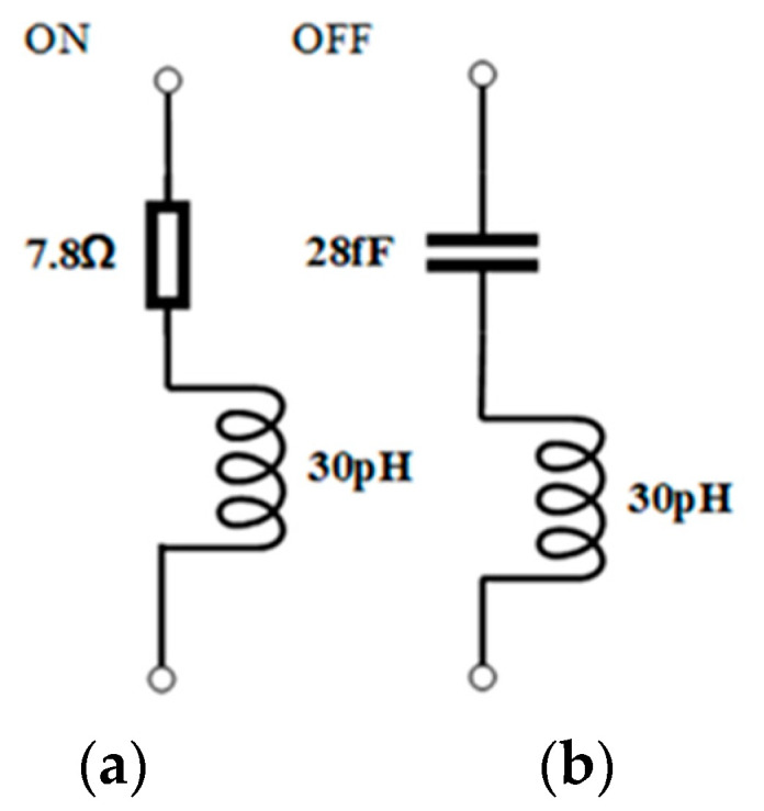
Analogous circuit of p-i-n diodes in different states: (a) ON state, (b) OFF state.
Analysis of the RMM in transmitted and reflected modes is carried out independently. The parts below provide a thorough analysis.
3. Transmission Mode
When the x-polarized incoming waves are impinged on the RMM from top to bottom, the transmitted wave will be converted in polarization due to matching electric fields being excited. In the meantime, the RMM operates in transmission mode, and works as a polarizer.
3.1. Working Principle
To realize the polarized conversion of LP-to-CP with an x-polarized incoming wave impinging on the RMM, the element structure should be asymmetric along the x-direction and embrace a 45°-inclined H-shape, which can translate the x-polarized wave into two perpendicularly polarized waves and produce different accumulations of phases. As depicted in Figure 4, the x-polarized incoming wave can be divided into the tangential (u) and normal (v) directions at the center point of the inclined H-shape, and can be written as
| (1) |
where ; is the wavenumber; and , and are the unit vectors with respect to the x-axis and u- and v-directions, respectively. The transmitted fields can be written using
| (2) |
where , and are transmission coefficients.
Figure 4.
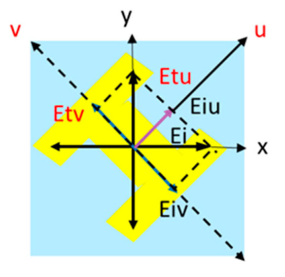
The electric field along the x-axis splitting into the u and v components, where the right-hand coordinate system is assumed, and the z axis is directed towards the reader.
When , and ,
| (3) |
which implies that the EM waves are converted from the x-polarized waves to the y-polarized ones. When the phase differences , the polarization of the transmission wave is still along the x-direction. If , the incoming linearly polarized waves are transformed into circularly polarized waves, which can be described as follows:
| (4) |
where are transmission coefficients of co- and cross-polarized components under the x-polarized incident wave. It is clear from Equation (4) that the phase differences and the co-polarized and cross-polarized transmission coefficients ( and ) can be used to identify the state of polarization for the transmitted field. When , a polarized conversion of LP-to-LHCP and LP-to-RHCP is achieved, respectively, whereas when , an elliptic polarization wave is generated.
From Equation (4), it is concluded that controlling polarization can be accomplished through altering , which is mostly decided by the structure of resonant unit cells. is a function of frequency when metasurfaces are unreconfigurable structures, meaning that distinct polarized conversion functions will be generated at distinct frequencies [37].
3.2. Simulation Results
We further discuss circular polarization conversion through the axial ratio (AR). The transmission coefficients of two waves with orthogonal polarization under an x-polarized incoming wave can be used to determine the AR parameter, which is crucial for assessing the electromagnetic waves’ level of circular polarization.
| (5) |
From the previous analysis, we are aware that in order to produce circularly polarized waves, the two orthogonal components of the transmitted electric field must have a phase difference of Δφ = ±90° and equal amplitude, i.e., . If the AR is less than 3 dB, it is roughly circular polarization in practice.
The full-wave simulations are used to examine the RMM’s transmission magnitudes and phase discrepancies in order to verify our design. In Figure 5, the simulated co-polarized and cross-polarized transmission magnitudes and phase differences are displayed when the diode is forward-biased. It is evident that and are over −10 dB and nearly equal within the working frequency ranges of 7.65–7.7 GHz and 6.1–6.6 GHz, and that the phase differences are close to 270°, which indicates the transmission of RHCP waves. When the diode is reversebiased, Figure 6 displays the simulated co-polarized and cross-polarized transmission magnitudes and phase discrepancies. Thus, an excellent circularly polarized transmission wave is achieved in the two bands of 6.5–6.6 GHz and 7.65–7.7 GHz in both the ON and OFF states.
Figure 5.

Simulated co-polarized and cross-polarized transmission magnitudes and phase differences under the x-polarized EM wave in the ON state.
Figure 6.

Simulated co-polarized and cross-polarized transmission magnitudes and phase differences under the x-polarized EM wave in the OFF state.
In order to look into the impact of oblique incidence on transmission performance, the variation in transmission performances is investigated for different obliques under the x-polarized EM waves from top to bottom. Figure 7 and Figure 8 present the co- and cross-polarized transmitted magnitudes and phase differences versus operating frequency at oblique incidence with the incidence angles , , and in the ON and OFF states, respectively. It is obvious from Figure 7 and Figure 8 that the curved lines of the simulated co- and cross-polarization transmission magnitudes and phase differences are nearly coincident with those under normal incidence in the ON and OFF states, respectively, which shows the great angular stability in transmission mode in the ON and OFF states.
Figure 7.

Simulated co- and cross-polarization transmission magnitudes and phase differences for different incident angles under the x-polarized EM waves in the ON state.
Figure 8.

Simulated co- and cross-polarization transmission magnitudes and phase differences for different incident angles under the x-polarized EM waves in the OFF state.
4. Reflection Mode
When the y-polarization incident wave is impinged on the RMM from bottom to top, by switching the p-i-n states and designing the discontinuous reflection phases, the wavefront of EM waves can be freely tailored, opening a wide range of new phenomena and applications, including beam patterns with two beams and four beams. Meanwhile, the RMM works in reflection mode and acts as a reflector.
4.1. Performance Analysis
According to the analysis above, we can determine that four open trapezoidal patches on metal layer 5 serve as an AMC in conjunction with the metal grating on metal layer 3, which acts as the ground of the AMC. To verify this, the simulated reflection performances are analyzed. An AMC can be generated by impinging y-polarized EM waves on the MS from bottom to top almost in the frequency range of 14–16 GHz, which can be used for stealth materials in radars [39] or high-gain antennas [40]. Figure 9 presents reflection coefficients, phases, and phase differences of the proposed flexible regulated MS under the y-polarized normal incidence in the ON and OFF states within a bandwidth of 14–16 GHz. As shown in Figure 9a, folded reflected phases are almost in the range of , and most of the incident waves are reflected with reflected coefficients () greater than −10 dB in each state in the operating band, which indicates that the proposed MS works as an AMC. Furthermore, it is obvious from Figure 9b that the reflection phases are discernibly distinct in every state, and the phase discrepancies between adjacent states fall in the range of (180° − 10°, 180° + 10°) around 15.15 GHz, 15.54 GHz, and 15.8 GHz, by switching simultaneously the four p-i-n diodes on metal layer 5 to operate in the ON/OFF states. Therefore, 1-bit coding elements can be obtained at 15.15 GHz, 15.54 GHz, and 15.8 GHz, meaning that the gradient reflection phase distribution of and can be produced by the suggested metasurface working from state 1 to state 2. As a result, the element configuration in each state can be thought of as a fundamental digital element. Two different element configurations yield 1 bit, simulating the state 1 and state 0 units, respectively.
Figure 9.

Simulated reflection coefficients of the presented MS in the ON and OFF states: (a) reflection coefficient; (b) reflection phase and reflection phase differences between p-i-n diode ON and OFF states.
Subsequently, the performance of reflection is analyzed for various oblique incidences in reflection modes. The reflection magnitudes and phases versus operating frequency with variable incident angles in the ON and OFF states are shown in Figure 10 and Figure 11. From these figures, it is concluded that the reflection performance is almost stable up to 30° in the ON state and 20° in the OFF state in the band of 14–16 GHz, which implies that the proposed RMM possesses better stability at oblique incidence in the reflection mode. The above findings have conclusively demonstrated that the suggested RMM can still operate as a digital coding MS at 20 degrees of oblique illumination in each state. Greater incident angles cause the EM wave to take an extra path between the ground (metal layer 3) and the bottom, which increases the phase difference, resulting in destructive interference [38],
| (6) |
where represents the incident angle with respect to normal incidence, signifies the vector of wave propagation in free space, indicates the thickness of the substrate, and . Reflection performance degrades severely for incidence angles more than 30° in the ON state and 20° in the OFF state. Folded reflection phases are out of . It is obvious from Equation (6) that higher-order modes or grating lobes are the cause of the performance deterioration. It can be concluded from the above analysis that the overall trend in the reflection performance under oblique incidence also meets the majority of large-angle incidence design criteria despite not being as stable as the transmission mode.
Figure 10.

Simulated reflection magnitudes and phases for different incident angles in the ON states under the y-polarized wave from bottom to top: (a) magnitudes, (b) phases.
Figure 11.

Simulated reflection magnitudes and phases for different incident angles in the OFF states under the y-polarized wave from bottom to top: (a) magnitudes, (b) phases.
4.2. Reconfigurable Reflection Coding MSs
These coding particles could be arranged to form a coding metasurface with various encoding sequences in two dimensions, which possesses different reflection patterns. According to array theory, the radiation pattern of a given encoding sequence, which is made up of equal-sized unit cells with dimension D, can be analytically calculated. In the far-field area, the specific characteristic of each coding particle becomes hazy because of the subwavelength characteristic of the digital particle with a reflection phase of (either or in the 1-bit case) for the mnth element. The far-field-function-reflected metasurface at the normal incidence of plane waves is written as
| (7) |
where the lattice pattern function is denoted by and the elevation and azimuth angles are represented by and , respectively. The relative phase of the “0” element has been assumed to be zero for simplicity’s sake, and the term in Equation (7) has been neglected because it becomes ambiguous in the far-field. Using any given encoding sequence, we may determine the directivity function from Equation (7), which can be represented as
| (8) |
In order to investigate the aforementioned beam modulation performance, the 1-bit digital MS is designed, which consists of 13 × 13 unit cells in the total size of 234 mm × 234 mm. The various reflection fields will be produced by various coding sequences in the reflection mode, and each particle can be independently controlled. Full-wave numerical simulations are used to finish all numerical simulations. Figure 12 presents the reflection pattern of the proposed RMM with the 0001111000111 coding sequence, under the y-normal illumination from bottom to top. The coding sequence is shown in Figure 12a. From Figure 12b, it is evident that normal-incidence plane waves are redirected in two symmetrical directions, which is consistent with the theoretical predictions in Equation (7). Figure 13 depicts the reflection pattern of the chess-board periodic coding MS under the y-normal illumination from bottom to top. The chess-board coding sequence with 01/10 is shown in Figure 13a. From Figure 13b, it can be obviously found that the normal-incidence plane waves are scattered in four symmetrical directions, which further verifies the theory derivation results in Equation (7). The comparison of the designed RMM with some existing multifunction MSs for full space are listed in Table 2. It can be observed that the proposed RMM possesses real-time multifunctional adjustability and a low profile. Further, transmission and reflection of the designed RMM have good angular stability compared to other existing multiple MSs.
Figure 12.

Schematic illustration of 0001111…… coding MSs under the y-normal illumination from bottom to top with dual-beam pattern: (a) coding phase profile, (b) simulated 3D far-field patterns.
Figure 13.

Schematic illustration of chess-board periodic coding metasurface under the y-normal illumination with quad-beam pattern: (a) coding phase profile, (b) simulated 3D far-field patterns.
Table 2.
Comparison of the proposed RMM with some recently reported full-space MSs.
5. Conclusions
In this paper, an important design has been implemented: a flexible transmission-reflection-integrated RMM with p-i-n diodes and an AS, which can realize the EM wave polarization conversion from the LP to CP in the transmission mode. As a good structure from top to bottom, it can modulate reflection beam patterns by switching the p-i-n diodes embedded into metal 5. Taking the transmitted mode as an example, the physical mechanism of multifunctionalities was developed. An RMM with elements was designed and simulated, which can scatter reflection beam patterns with two beams and four beams by switching p-i-n diodes. The efficiency of the suggested design is confirmed by the simulation results, which agree with the theoretical predictions. Our design provides a new method for building an RMM in full space and possesses enormous potential applications in radar and wireless communications.
Author Contributions
All authors have significantly contributed to the research presented in this manuscript; S.Z. presented the main idea and wrote the manuscript; W.C. and J.W. edited the manuscript; T.W. and Y.W. (Yiyin Wang) reviewed and revised the manuscript. Y.W. (Yanxia Wang) and D.Z. finished some simulations. All authors have read and agreed to the published version of the manuscript.
Data Availability Statement
The original contributions presented in the study are included in the article, further inquiries can be directed to the corresponding author.
Conflicts of Interest
Authors Yanxia Wang and Dongsheng Zhou were employed by Hebei Jinghe Electronic Technology Incorporated Company. The remaining authors declare that the research was conducted in the absence of any commercial or financial relationships that could be construed as a potential conflict of interest.
Funding Statement
This work is supported by the Major Science and Technology Programs for Universities in Hebei under Grant 241130447A and by the Natural Science Foundation of Guangxi Province (2024GXNSFAA010178).
Footnotes
Disclaimer/Publisher’s Note: The statements, opinions and data contained in all publications are solely those of the individual author(s) and contributor(s) and not of MDPI and/or the editor(s). MDPI and/or the editor(s) disclaim responsibility for any injury to people or property resulting from any ideas, methods, instructions or products referred to in the content.
References
- 1.Demetre J.S., Smy T.J., Gupta S. Static Metasurface Reflectors With Independent Magnitude and Phase Control Using Coupled Resonator Configuration. IEEE Trans. Antennas Propag. 2023;71:3536–3545. doi: 10.1109/TAP.2023.3242076. [DOI] [Google Scholar]
- 2.Yang J., Yang W.X., Qu K., Zhao J.M., Jiang T., Chen K., Feng Y.J. Active polarization-converting metasurface with electrically controlled magnitude amplification. Opt. Express. 2023;31:28979–28986. doi: 10.1364/OE.499458. [DOI] [PubMed] [Google Scholar]
- 3.Sleasman T., Duggan R., Awadallah R.S., Shrekenhamer D. Dual-Resonance Dynamic Metasurface for Independent Magnitude and Phase Modulation. Phys. Rev. Appl. 2023;20:014004. doi: 10.1103/PhysRevApplied.20.014004. [DOI] [Google Scholar]
- 4.Mueller J.P.B., Rubin N.A., Devlin R.C., Groever B., Capasso F. Metasurface Polarization Optics: Independent Phase Control of Arbitrary Orthogonal States of Polarization. Phys. Rev. Let. 2017;118:113901. doi: 10.1103/PhysRevLett.118.113901. [DOI] [PubMed] [Google Scholar]
- 5.Rudakova N.V., Bikbaev R.G., Tyryshkina L.E., Vetrov S.Y., Timofeev I.V. Tuning Q-Factor and Perfect Absorption Using Coupled Tamm States on Polarization-Preserving Metasurface. Photonics. 2023;10:1391. doi: 10.3390/photonics10121391. [DOI] [Google Scholar]
- 6.Smith D.R., Padilla W.J., Vier D.C., Nemat-Nasser S.C., Schultz S. Composite medium with simultaneously negative permeability and permittivity. Phys. Rev. Lett. 2000;84:4184–4187. doi: 10.1103/PhysRevLett.84.4184. [DOI] [PubMed] [Google Scholar]
- 7.Pendry J.B. Negative refraction makes a perfect lens. Phys. Rev. Lett. 2000;85:3966–3969. doi: 10.1103/PhysRevLett.85.3966. [DOI] [PubMed] [Google Scholar]
- 8.Li Y.C., Wan S.C., Zhao R.Q., Zhu Z., Li W.J., Guan C.Y., Yang J., Bogdanov A., Belov P., Shi J.H. Huygens’ metasurface: From anomalous refraction to reflection. Opt. Commun. 2024;565:130648. doi: 10.1016/j.optcom.2024.130648. [DOI] [Google Scholar]
- 9.Aieta F., Genevet P., Yu N.F., Kats M.A., Gaburro Z., Capasso F. Out-of plane reflection and refraction of light by anisotropic optical antenna metasurfaces with phase discontinuities. Nano Lett. 2012;12:1702–1706. doi: 10.1021/nl300204s. [DOI] [PubMed] [Google Scholar]
- 10.Song Y.C., Ding J., Guo C.J., Ren Y.H., Zhang J.K. Ultra-broadband backscatter radar cross section reduction based on polarization-insensitive metasurface. IEEE Antennas Wirel. Propag. 2016;15:329–331. doi: 10.1109/LAWP.2015.2443853. [DOI] [Google Scholar]
- 11.Zhang H., Wang X., Liu Y., Liu C., Dong H. A Combined Subdomain Method of Moments and Asymptotic Waveform Evaluation for Fast Wideband Bistatic Radar Cross Section Prediction. IEEE T Antennas Propag. 2024;72:5900–5909. doi: 10.1109/TAP.2024.3413361. [DOI] [Google Scholar]
- 12.Li Y.B., Wan X., Cai B.G., Cheng Q., Cui T.J. Frequency-controls of electromagnetic multi-beam scanning by metasurfaces. Sci. Rep. 2014;4:6921. doi: 10.1038/srep06921. [DOI] [PMC free article] [PubMed] [Google Scholar]
- 13.Chen T.T., Song L.Z. A Simplified Dual-Polarized Beam-Scanning Reflectarray Using Novel Wheel-Rudder Elements. IEEE Antennas Wirel. Propag. 2024;23:2311–2315. doi: 10.1109/LAWP.2024.3388162. [DOI] [Google Scholar]
- 14.Yu H., Zhang Z.Y., Su J.X., Qu M.J., Li Z.R., Xu S.H., Yang F. Quad-Polarization Reconfigurable Reflectarray With Independent Beam-Scanning and Polarization Switching Capabilities. IEEE Trans. Antennas Propag. 2023;71:7285–7298. doi: 10.1109/TAP.2023.3291460. [DOI] [Google Scholar]
- 15.Hu J.H., Guo Z.Y., Shi J.Y., Jiang X., Chen Q.M., Chen H., He Z.X., Song Q.H., Xiao S.M., Yu S.H., et al. A metasurface-based full-color circular auto-focusing Airy beam transmitter for stable high-speed underwater wireless optical communications. Nat. Commun. 2024;15:2944. doi: 10.1038/s41467-024-47105-x. [DOI] [PMC free article] [PubMed] [Google Scholar]
- 16.Shrestha S., Overvig A.C., Lu M., Stein A., Yu N.F. Broadband achromatic dielectric metalenses. Light. Sci. Appl. 2018;7:85. doi: 10.1038/s41377-018-0078-x. [DOI] [PMC free article] [PubMed] [Google Scholar]
- 17.Grady N.K., Heyes J.E., Chowdhury D.R., Zeng Y., Reiten M.T., Azad A.K., Taylor A.J., Dalvit D.A.R., Chen H.T. Terahertz metamaterials for linear polarization conversion and anomalous refraction. Science. 2013;340:1304–1307. doi: 10.1126/science.1235399. [DOI] [PubMed] [Google Scholar]
- 18.Yuan Y.Y., Wu Q., Burokur S.N., Zhang K. Chirality-Assisted Phase Metasurface for Circular Polarization Preservation and Independent Hologram Imaging in Microwave Region. IEEE Trans. Microw. Theory. 2023;71:3259–3272. doi: 10.1109/TMTT.2023.3256527. [DOI] [Google Scholar]
- 19.Gao X., He L.Y., Yin S.J., Xue C.H., Wang G.F., Xie X.M., Xiong H., Cheng Q., Cui T.J. Ultra-Wideband Low-RCS Circularly Polarized Antennas Realized by Bilayer Polarization Conversion Metasurfaces and Novel Feeding Networks. IEEE Trans. Antennas Propag. 2024;72:1959–1964. doi: 10.1109/TAP.2023.3344211. [DOI] [Google Scholar]
- 20.Hu Y.Q., Luo X.H., Chen Y.Q., Liu Q., Li X., Wang Y.S., Liu N., Duan H.G. 3D integrated metasurfaces for full-colour holography. Light. Sci. Appl. 2019;8:86. doi: 10.1038/s41377-019-0198-y. [DOI] [PMC free article] [PubMed] [Google Scholar]
- 21.Yu N.F., Genevet P., Kats M.A., Aieta F., Tetienne J.P., Capasso F., Gaburro Z. Light propagation with phase discontinuities: Generalized laws of reflection and refraction. Science. 2011;334:333–337. doi: 10.1126/science.1210713. [DOI] [PubMed] [Google Scholar]
- 22.Zhang S.L., Cao W.P., Wu T.S., Wang J., Wei Y. The Design of a Multifunctional Coding Transmitarray with Independent Manipulation of the Polarization States. Micromachines. 2024;15:1014. doi: 10.3390/mi15081014. [DOI] [PMC free article] [PubMed] [Google Scholar]
- 23.Yin T., Ren J., Chen Y.J., Xu K.D., Yin Y.Z. Highly Integrated Reconfigurable Shared-Aperture EM Surface With Multifunctionality in Transmission, Reflection, and Absorption. IEEE Trans. Antennas Propag. 2024;72:6789–6794. doi: 10.1109/TAP.2024.3418138. [DOI] [Google Scholar]
- 24.Xing H.R., Tang C., Li Z.W., Wang M.J., Fan C., Zheng H.X., Li E.R. Three-Polarization-Reconfigurable Antenna Array Implemented by Liquid Metal. IEEE Antennas Wirel. Propag. 2024;23:374–378. doi: 10.1109/LAWP.2023.3325217. [DOI] [Google Scholar]
- 25.Afsari A., Van Veen B.D., Behdad N. An Electronically Reconfigurable Matching and Decoupling Network for Two-Element HF Antenna Arrays. IEEE Trans. Antennas Propag. 2024;72:6332–6347. doi: 10.1109/TAP.2024.3425049. [DOI] [Google Scholar]
- 26.Guo Q.X., Hao F.S., Qu M.J., Su J.X., Li Z.R. Multiband Multifunctional Polarization Converter Based on Reconfigurable Metasurface. IEEE Antennas Wirel. Propag. 2024;23:1241–1245. doi: 10.1109/LAWP.2024.3350034. [DOI] [Google Scholar]
- 27.Ratni B., de Lustrac A., Piau G.P., Burokur S.N. Electronic control of linear-to-circular polarization conversion using a reconfigurable metasurface. Appl. Phys. Lett. 2017;111:214101. doi: 10.1063/1.4998556. [DOI] [Google Scholar]
- 28.Huang C., Zhang C.L., Yang J.N., Sun B., Zhao B., Luo X.G. Reconfigurable metasurface for multifunctional control of electromagnetic waves. Adv. Opt. Mater. 2017;5:1700485. doi: 10.1002/adom.201700485. [DOI] [Google Scholar]
- 29.Lor C., Phon R., Lim S. Reconfigurable transmissive metasurface with a combination of scissor and rotation actuators for independently controlling beam scanning and polarization conversion. Microsyst. Nanoeng. 2024;10:40. doi: 10.1038/s41378-024-00671-y. [DOI] [PMC free article] [PubMed] [Google Scholar]
- 30.Ning Y.F., Zhu S.C., Chu H.B., Zou Q., Zhang C., Li J.X., Xiao P., Li G.S. 1-bit Low-Cost Electronically Reconfigurable Reflectarray and Phased Array Based on p-i-n Diodes for Dynamic Beam Scanning. IEEE T Antennas Propag. 2024;72:2007–2012. doi: 10.1109/TAP.2023.3325650. [DOI] [Google Scholar]
- 31.Zhang X.Y., Kong X.K., Zhou S.C., Liu P.Q., Zou Y.K., Cheng J.L., Pang X.Y., Gao S. High-accuracy beam generation and scanning using reconfigurable coding metasurface. J. Phys. D Appl. Phys. 2024;57:385108. doi: 10.1088/1361-6463/ad5aa9. [DOI] [Google Scholar]
- 32.Fu X.J., Yang F., Liu C.X., Wu X.J., Cui T.J. Terahertz beam steering technologies: From phased arrays to field-programmable metasurfaces. Adv. Opt. Mater. 2020;8:190062. doi: 10.1002/adom.201900628. [DOI] [Google Scholar]
- 33.Sobczyk A., Mędoń K.F., Kowalczyk M.A., Suszek J., Zdrojek M., Sypek M. Ultra-low reflection of sub-THz waves in graphene-based composite with metasurface for stealth technology. Opt. Express. 2024;18:32118–32127. doi: 10.1364/OE.531259. [DOI] [PubMed] [Google Scholar]
- 34.Torabi E.S., Fallahi A., Yahaqhi A. Evolutionary optimization of graphene-metal metasurfaces for tunable broadband terahertz absorption. IEEE T Antennas Propag. 2017;65:1464–1467. doi: 10.1109/TAP.2016.2647580. [DOI] [Google Scholar]
- 35.Xing B.B., Liu Z.G., Lu W.B., Chen H., Zhang Q.B. Wideband microwave absorber with dynamically tunable absorption based on graphene and random metasurface. IEEE Antennas Wirel. Propag. Lett. 2019;18:2602–2606. doi: 10.1109/LAWP.2019.2944966. [DOI] [Google Scholar]
- 36.Yang W.C., Zhou C.Y., Xue Q., Wen Q.Y., Che W.Q. Millimeter-Wave Frequency-Reconfigurable Metasurface Antenna Based on Vanadium Dioxide Films. IEEE T Antennas Propag. 2021;69:4359–4369. doi: 10.1109/TAP.2020.3048551. [DOI] [Google Scholar]
- 37.Zhang S.L., Cao W.P., Wu T.S., Wang J., Li H., Duan Y.L., Rong H.Y., Zhang Y.L. Transmission-Reflection-Integrated Multifunctional Passive Metasurface for Entire-Space Electromagnetic Wave Manipulation. Materials. 2023;16:4242. doi: 10.3390/ma16124242. [DOI] [PMC free article] [PubMed] [Google Scholar]
- 38.Yang H., Wang S.C., Li P., He Y., Zhang Y.J. A Broadband Multifunctional Reconfigurable Polarization Conversion Metasurface. IEEE Trans. Antennas Propag. 2024;71:5759–5767. doi: 10.1109/TAP.2023.3266498. [DOI] [Google Scholar]
- 39.Galarregui J.C.I., Pereda A.T., de Falcon J.L.M., Ederra I., Gonzalo R., de Maagt P. Broadband Radar Cross-Section Reduction Using AMC Technology. IEEE Trans. Antennas Propag. 2013;61:6136–6143. doi: 10.1109/TAP.2013.2282915. [DOI] [Google Scholar]
- 40.Su R., Gao P., Wang R.D., Wang P. High-gain broadside dipole planar AMC antenna for 60 GHz applications. Electron. Lett. 2018;5:407–408. doi: 10.1049/el.2017.2519. [DOI] [Google Scholar]
- 41.Qin Z., Li Y.F., Wang H., Li C.C., Liu C., Zhu Z.B., Yuan Q., Wang J.F., Qu S.B. Transmission Reflection Integrated Programmable Metasurface for Real-Time Beam Control and High Efficiency Transmission Polarization Conversion. Ann. Phys. 2022;535:202200368. doi: 10.1002/andp.202200368. [DOI] [Google Scholar]
- 42.Sun S., Ma H.F., Chen Y.F., Cui T.J. Transmission-Reflection-Integrated Metasurface with Simultaneous Amplitude and Phase Controls of Circularly Polarized Waves in Full Space. Laser Photonics Rev. 2024;18:2300945. doi: 10.1002/lpor.202300945. [DOI] [Google Scholar]
- 43.Zhang C., Gao J., Cao X.Y., Li S.J., Yang H.H., Li T. Multifunction Tunable Metasurface for Entire-Space Electromagnetic Wave Manipulation. IEEE Trans. Antennas Propag. 2020;68:3301–3306. doi: 10.1109/TAP.2019.2929438. [DOI] [Google Scholar]
- 44.Wang J.Y., Zhang Z.J., Huang C., Pu M.B., Lu X.J., Ma X.L., Guo Y.H., Luo J., Luo X.G. Transmission–Reflection-Integrated Quadratic Phase Metasurface for Multifunctional Electromagnetic Manipulation in Full Space. Adv. Opt. Mater. 2022;10:2102111. doi: 10.1002/adom.202102111. [DOI] [Google Scholar]
- 45.Cai T., Wang G.M., Tang S.W., Xu H.X., Duan J.W., Guo H.J., Guan F.X., Sun S.L., He Q., Zhou L. High-Efficiency and Full-Space Manipulation of Electromagnetic Wave Fronts with Metasurfaces. Phys. Rev. Appl. 2017;8:034033. doi: 10.1103/PhysRevApplied.8.034033. [DOI] [Google Scholar]
Associated Data
This section collects any data citations, data availability statements, or supplementary materials included in this article.
Data Availability Statement
The original contributions presented in the study are included in the article, further inquiries can be directed to the corresponding author.