Abstract
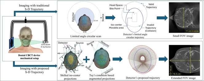
In dental imaging, Cone Beam Computed Tomography (CBCT) is a widely used imaging modality for diagnosis and treatment planning. Small dental scanning units are the most popular due to their cost-effectiveness. However, these small systems have the limitation of a small field of view (FOV) as the source and detector move at a limited angle in a circular path. This often limits the FOV size. In this study, we addressed this issue by modifying the source-detector trajectory of the small dental device. The main goal of this study was to extend the FOV algorithmically by acquiring projection data with optimal projection angulation and isocenter location rather than upgrading any physical parts of the device. A novel algorithm to implement a Volume of Interest (VOI) guided trajectory is developed in this study based on the small dental imaging device's geometry. In addition, this algorithm is fused with a previously developed off-axis scanning method which uses an elliptical trajectory, to compensate for the existing constraints and to further extend the FOV. A comparison with standard circular trajectory is performed. The FOV of such a standard trajectory is a circle of 11 cm diameter in the axial plane. The proposed novel trajectory extends the FOV significantly and a maximum FOV of 19.5 cm is achieved with the Structural Similarity Index Measure (SSIM) score ranging between (≈98-99%) in different VOIs. The study results indicate that the proposed source-detector trajectory can extend dental imaging FOV and increase imaging performance, which ultimately results in more precise diagnosis and enhanced patient outcomes.
Keywords: Dental CBCT, Image reconstruction, Field of view, Trajectory optimization, Interventional radiology
Graphical abstract
Highlights
-
•
A novel source-detector trajectory, proposed for dental CBCT field of view (FOV) expansion.
-
•
The achieved field of view is expanded from 11 cm to a maximum of 19.5 cm.
-
•
The FOV extension is done algorithmically rather than modifying the device hardware.
-
•
Image quality of the proposed trajectory outperforms the standard trajectory.
1. Introduction
Cone Beam Computed Tomography (CBCT) is one of the most rapidly growing imaging modalities in medicine, especially for image-guided therapy and surgical planning. The early stage of CBCT imaging application has been recorded in the late '70s as the projections from cross-plane rays [1]. It was demonstrated that a CBCT scan can provide extensive 2D projection data, as infinite X-ray beams radiate from various angles and intersect each point of the imaging object. Following, the circular source-detector trajectory is the simplest and easy-to-implement trajectory to image a point or spherical object [2]. Given its ease of use, this approach is utilized extensively in medical CBCT scanning and reconstruction applications. Almost two decades later, CBCT was used for the first time in dentistry with the same trajectory principle [3], [4]. However, in clinical practice, the circular trajectory is not necessarily the best way to achieve optimum 3D reconstruction. Hence, the optimum trajectory varies depending on the application circumstance.
Despite its limitation of imaging soft tissues, CBCT is incredibly useful for evaluating anatomical dental treatments. Small-volume CBCT is useful in endodontics procedures for mapping the bone around the tooth root and assessing the anatomy of the root canal, aiding the pre-surgical inspection [5]. This leads to the development of dental implant-based therapies since the key anatomical characteristics, surgical guide design, and implant planning can also be reviewed [6], [7], [8]. Furthermore, CBCT scanning is beneficial to generate 3D data to analyze the dilacerated, unerupted, supernumerary teeth, and clefts in the cases of inadequate information for orthodontic treatments. CBCT also can help treat dental trauma when 2D scans cannot provide sufficient information for surgical planning [9], [10], [11]. Moreover, CBCT is a decent alternative to multi-detector computed tomography (MDCT) imaging for chronic rhinosinusitis surgery planning as it has comparable accuracy to sinus endoscopy [12], [13]. CBCT scan is also applicable to the primary diagnosis and supervision of temporomandibular joint (TMJ) bone disorder [14].
Typically, based on the size of Field of View (FOV), the CBCT can be grouped into four types including dentoalveolar CBCT (with FOV<8 cm), maxillo-mandibular CBCT (with FOV 8–15 cm), skeletal CBCT (with FOV 15–21 cm), and head and neck CBCT (with FOV>21 cm) [15], [16]. The FOV size requirement of dental CBCT scan can be diversified based on the region of interest and treatment type [17]. This makes the treatment more complex in medical practice as considering the different imaging organs and tasks, a different CBCT scanning device is required. Moreover, it is challenging to image different ROIs with a small CBCT unit, where the FOV is restricted. The simplest fix to this small FOV problem is to use larger detectors to capture more projection information. However, the drawback of this approach is the high cost associated with such large detectors. Another solution to this FOV expansion issue is to fuse more sets of scan data or to stitch separately reconstructed volumes. However, this approach induces increased exposure to radiation and complexity in maintaining stitching accuracy [18], [19]. The shifted detector and collimation of the X-ray beams can also be a solution. However, it requires hardware modifications during the scan [20].
Alternatively, source-detector trajectory manipulation can address the limited FOV problem which could maximize the VOI imaging volume by acquiring heterogeneous projection data for reconstruction. Source-detector trajectory optimization of CBCT is an extensive research field which has gained a lot of attention in recent years. Numerous trajectories were developed over the years for different purposes such as image quality improvement, collision avoidance, dose reduction and metal, CBCT artifact reduction, and FOV extension [21]. However, the trajectories introduced for FOV extension in medical imaging have focused on expanding the FOV either in the longitudinal direction (in the perpendicular direction of the source-detector plane) or the lateral direction (in the source-detector plane) expansion. In the earlier research studies on longitudinal FOV expansion, numerous combinations of different shapes and sizes of arcs, circles, and linear paths have been tested. Two same distant linear paths reinforced with a circle, a linear path with two arcs, parallel circular trajectory, double overlapping cone beam circular orbit, an ellipse-line-ellipse path, an extended version of ellipse-line-ellipse, and multiple scans with table translation were proposed [22], [23], [24], [25], [26], [27], [28]. Following, helical trajectory, reverse helical, and multi-turn reverse helical trajectory were also examined [29], [30], [31], [32]. All these approaches exhibit good results, while the trajectory involved with the movement in the perpendicular z-axis, makes the trajectory a non-planner 3D path. Whereas, in the small dental CBCT scanning units the 2D planner trajectories are widely used. In addition, for longitudinal FOV extension multiple X-ray source approach was used [33], however, the multiple X-ray method has hardware and software complexity as well as has increased radiation dose due to the multiple X-ray sources. For circular trajectory, the FOV is always a circle in the source-detector plane. As the endeavors of lateral FOV extension, non-stationary iso-centric elliptical trajectory, complimentary circular scan, rotated detector, and dynamic detector offset approaches are used which are the different forms of offset detector or displaced detector approach [20], [34], [35], [36]. The displaced detector approach has the additional burden of collimation adjustment and may not fulfill the data incompleteness according to Tuy's conditions [2] which makes it challenging for the generally used reconstruction algorithms as FDK [37] to reconstruct the correct 3D volume.
Despite all these approaches, according to our best knowledge there is still no study that has developed optimal source-detector trajectories for FOV expansion specifically for dental imaging. Moreover, all the aforementioned studies were developed based on experimental trials with a trial and error approach, none of these studies were developed based on a trajectory optimization pipeline according to specific volumes/regions of interest (VOI/ROI) based on imaging requirements. The goal of this study is to develop a VOI-guided trajectory aiming to extend the FOV and to maximize the image quality at the interested VOIs. In doing so, an algorithm was developed to establish such a trajectory and later on it was fused with a previously developed off-axis scanning method which uses an elliptical trajectory under certain movement restrictions [34]. The proposed algorithm lifts the restriction and extends the FOV of the small dental CBCT device with excellent image quality.
2. Methodology
The prime task of this study is to develop a source-detector trajectory and to apply the most suitable reconstruction algorithm to expand the lateral FOV of the small dental unit while maintaining the diagnostic quality. In section 2.1, the geometry of the experimental device is explained. Then, in section 2.2, the experimental phantoms and the Volume of Interests (VOIs) of the imaging was briefly explained. Section 2.3 depicts the possible region of the trajectory area, and then in section 2.4 the process of the trajectory development is explained. Section 2.5 describes the image reconstruction algorithms that has been used in this study and in section 2.6 all the different experiments of this study have been explained. Finally, in section 2.7, all the image quality measurement metrics used in this study are described with their ideal characteristics. TIGRE: MATLAB/Python-GPU-based toolbox was used for all the simulation, reconstruction, and validation in this study [38].
2.1. Geometry of the experimental CBCT unit
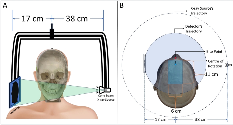
In this study, we simulated the geometry of the small dental CBCT unit which has the freedom to translate the gantry within a certain area during the scanning (resulting a shifted isocenter for each projection in a rectangular region of , starting from behind the bite point of the machine geometry) as shown in Fig. 1. It has a center of rotation to detector distance of , and to X-ray source distance of , with a total source to detector distance of . Due to non-equal source-to-origin and detector-to-origin distances, the source and detector have different trajectory paths. For stationary iso-centric scan, the detector only performs a movement of about 195°angular area, whether the maximum allowable range is 240°. The device has a detector of pixel with resolution pitch.
Fig. 1.
The geometry of the dental CBCT system used in this study. A: The X-ray source, detector, and the patient position. B: The top view of the geometrical setup.
2.2. Anthropomorphic phantoms, the digital phantoms, and volume of interests (VOI)
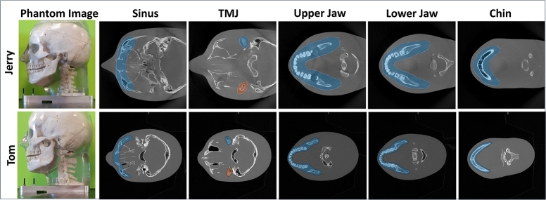
Two anthropomorphic head phantoms were used for this study. The phantom named Jerry is the smaller phantom which has a naso-occipital length of and a cranial breadth of . The standard head-sized phantom named Tom was used which has a naso-occipital length of and a cranial breadth of . Both phantoms were used for the development and testing of the proposed trajectory development algorithm (described in the section: 2.4 and 2.6).
Jerry digital phantom: A large-size CBCT reconstructed volume of pixels with of resolution was used as the digital phantom for Jerry to perform the trajectory computer simulations to produce the Digitally Rendered Radiographs (DRR) or synthetic projections, and to reconstructed image's quality testing. These DRRs are computed in TIGRE using the mathematical model described in Section-2.4.3 and 2.5 for all the experiments-2.6.1, 2.6.2, and 2.6.3
Tom digital phantom: For Tom, a digital phantom of pixels with a resolution of , was used same as Jerry.
For both the phantoms five volumes of interest (VOI) were selected to reconstruct; the maxillary sinus, the temporomandibular joint (TMJ) bones, the upper jaw, the lower jaw, and the chin as shown in Fig. 2. The primary target of the study was to achieve lateral FOV extension for the upper and lower jaw and then, apply more progressive approaches to reconstruct in both longitudinal directions for the maxillary sinus, TMJ, and the chin.
Fig. 2.
The anthropomorphic phantoms and the respective target VOIs to the image.
2.3. Possible movement space for trajectory: identifying the collision area
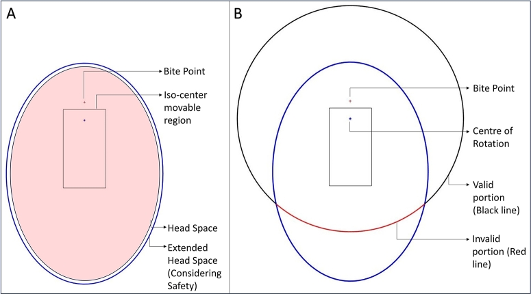
For the anthropomorphic phantoms described in section 2.2, the ideal patient positioning headspace is an elliptical region with and of major and minor axes respectively as shown in Fig. 3(A). An extra space has been taken around the existing elliptical region into the headspace considering the safety of the patient. Therefore, the experimental extended headspace is an elliptical region with major and minor axes of and respectively. There is a “Bite point” where the patient is supposed to bite during the scanning and there is an estimated rectangular region for the positioning of the iso-center during the scanning. Considering the center of rotation to the source and detector distance in the whole iso-center placement region, it is obvious that there is no possible collision between the patient and the source, however, the detector is closer to the head. Hence, it has some valid and invalid regions to move during the scan to avoid collision with the patient. In the existing setup, the device only can perform a limited angle circular scan due to the collision as shown in Fig. 3(B).
Fig. 3.
A: The pink shade is the original headspace, and the larger blue ellipse is the extended headspace. B: The semi-circular trajectory, black portion is the possible standard detector's trajectory, red portion is under collision region.
At the initial step, the possible detector's movable space was calculated. Section Appendix A in the supplementary materials explains the estimated valid and non-valid region for the detector movement which is also the search space for the trajectory of this study.
2.4. Development of the proposed trajectory
The proposed trajectory was developed based on the maximum scan data acquisition principle of Tuy's condition and by augmenting it to a modified iso-center shifted elliptical scan trajectory. In section 2.4.1, the principle of Tuy's condition is briefly explained. Section 2.4.2 illustrates how the initial VOI-guided trajectory estimation algorithm was developed and used to develop VOI-guided trajectory. Then, in section 2.4.3, the fusion of Tuy's condition-based VOI-guided algorithm with the modified iso-center shifted elliptical scan to develop the proposed trajectory was explained.
2.4.1. Tuy's condition
According to Tuy's condition [2], for obtaining maximum useful scan data, there should be infinite numbers of X-rays intersecting every 3D voxel in the imaging volume from infinite numbers of different directions. Therefore, for the simplest real-life implementation, the circular trajectory is widely used, however, as mentioned before it is not necessarily the best trajectory due to Tuy's second condition, which claims that the X-rays should intersect the 3D-voxels at the perpendicular angle of the tangent line drawn at the VOI boundary. In consequence, the VOI is supposed to be a cylinder-shaped region which is not desired or useful for all clinical applications.
2.4.2. VOI-guided trajectory construction
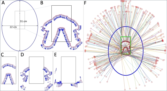
The symmetrical shape of the human head allows us to predict a common ROI polyline as shown in Fig. 4(A), (B), taken in the Z-axis in an intermediate axial plane ideally at the middle of the full 3D VOI. This plane was chosen to set the detector and source position vertically such that the central X-ray beam passes through it. The VOI-polyline was predicted by taking the union of all the five VOIs shown in Fig. 2. It was considered as the VOI's boundary to predict the tangent lines at the projection points. Then the perpendicular angles to the tangent lines were calculated which were used as the projection angles to meet Tuy's condition. However, to avoid collisions between the detector and the patient, it is not possible to move the isocentres at all calculated projection points. Therefore, the computed points were categorized into three different classes. category-I: the directly reachable points lie inside the iso-center moving region; category-II: the points that are outside of this region and calculated projection angles permit the creation of pseudo-points inside the region; and category-III: the points that are outside of the region and the projection angles do not allow the x-rays to pass through the VOI. The category-I points and the category-II pseudo-points were directly considered for the iso-center placement during the scanning. Category-III pseudo-points were computed as per the closest possible projection angles that pass through the iso-center moving region. Fig. 4(F) shows the predicted VOI-based trajectory heat map for iso-center and detector placement.
Fig. 4.
The VOI-guided trajectory, A: The headspace and iso-center movable region, B: The calculated points for iso-center placement, C: Category-I points, D: Category-II points, E: Category-III points, F: The Predicted VOI-guided trajectory.
2.4.3. Proposed extended FOV trajectory
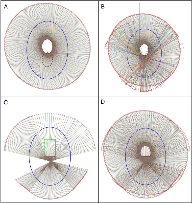
The predicted VOI-guided trajectory consists of scattered calculated iso-center points with non-sequential projection angles which makes it challenging to implement the trajectory directly in a scanner. Thus, the idea of the shifted iso-center rotation trajectory in an elliptical path described in [34] was implemented as Fig. 6(A) and then enhanced with the algorithm developed for the VOI-guided method described in Section-2.4.2 to replicate an elliptical path outside of the iso-center positioning area (Fig. 6(A, B)). The shifted iso-center trajectory has the limitation of detector movement such that the outmost X-ray beam and the detector should be tangential to the elliptical path to avoid non-sampling in the middle of the VOI. However, in this study, this movement constraint was lifted, and as a result for the larger acquisition, a void space appeared as no central X-ray beam of CBCT scan passes through the yellow-shaded region in Fig. 5. This limitation and FOV extension both were addressed by fusing the VOI-guided method to the shifted iso-center rotation trajectory. An imaginary elliptical VOI shown in Fig. 6(A) (the dotted ellipse) was taken in the calculation for the expansion of the FOV, additionally, it was designed such that it allows enough X-ray beams to pass through the missing region for data augmentation and to form the estimated proposed trajectory (Fig. 6(B)). As the scan geometry shown in Fig. 5, considering ϕ be the incident angle to the VOI, varying from 0 to π/2, γ be the half-fan span angle, and β be the projection angle and let a and b be the major and minor axis of the elliptical detector moving path respectively, the trajectory equation described in [34] gets extended as follows,
| (1) |
| (2) |
Thus, the coordinate of any point in the VOI is,
| (3) |
and, the X-ray source shift is defined by,
| (4) |
Fig. 6.
A: The shifted iso-centric scan and intended augmentation region (dotted ellipse) by VOI-guided method. B: The estimated proposed fusion trajectory. C: Smoothed fusion projections. D: The final proposed fusion trajectory.
Fig. 5.
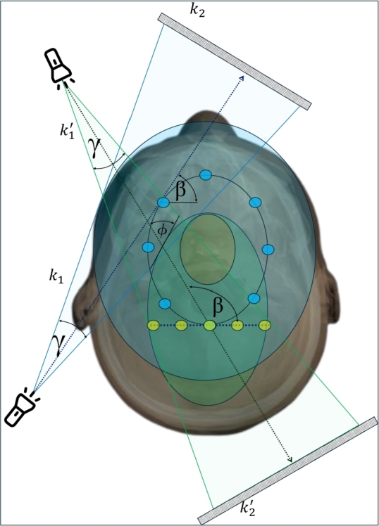
The projection geometry of the proposed trajectory.
The VOI-guided portion was smoothed on the post-processing as Fig. 6(C) to make it mechanically feasible. The final proposed trajectory looks like Fig. 6(D)
2.5. Image reconstruction
The imaging object X-ray attenuation is estimated from the projection value for the given X-ray source angle from Eq. (1) of . Hence, the projection on a point on the detector can be estimated as
| (5) |
Here, the source location s is estimated from Eq. (4) as and , where as L and D are the source-isocenter and source-detector distances respectively. is the estimated unit vector from to the point on the detector. The reconstruction system for the voxels calculated from the projections recorded in Eq. (5) can be described as
| (6) |
Whereas x is the voxel to be reconstructed, b is the projection data, and e is the error term which represents the reconstruction noise. A is the system matrix that relates the voxel values x to projections data b. The system matrix A is a sparse matrix which makes the system an ill-posed system to solve by direct mathematical calculations. Therefore, the iterative reconstruction form of Eq. (6) can be described as
| (7) |
Here, is the regularization function that is tuned over each iteration to obtain better image volume x. In this study, we have used two Gradient-based algorithms to regularize . The regularization process for these algorithms is described in the following paragraph OS-SART and ASD-POCS.
Ordered-Subset Simultaneous Algebraic Reconstruction Technique (OS-SART):
SART algorithm [39] is described by the following equation.
| (8) |
where is the iteration number, is the projection number, and is the relaxation parameter that tunes the effect of the gradient in each iteration to calculate the image in the next iteration . The OS-SART algorithm is the extension of SART where instead of considering only one projection per iteration a group of projections are taken for the calculation [40].
Eq. (8) represents an iterative method to solve the optimization problem in Eq. (7), where it specifically targets minimizing the data fidelity term . The update rule in Eq. (8) can be viewed as a gradient descent step aimed at reducing the residual, thereby working towards the overall minimization objective defined in Eq. (7).
Adaptive steepest descent projection onto convex sets (ASD-POCS):
ASD-POCS is the extended gradient-based algorithm which also considers the Total Variation (TV) in the smoothing process per iteration [41]. The ASD-POCS algorithm expresses the of Eq. (7) as.
| (9) |
Here are the voxel indices in 3D space. ASD-POCS takes the images created by the SART algorithm and then perform further TV optimization by the steepest gradient algorithm. Therefore, the final equation for ASD-POCS can be described as,
| (10) |
ASD-POCS optimizes the image such that where ε is the acceptable error between the observed and predicted projections.
Eq. (10) is a specific instance of the optimization problem in Eq. (7), where it focuses solely on minimizing the total variation (TV) norm, to deal with the data fidelity.
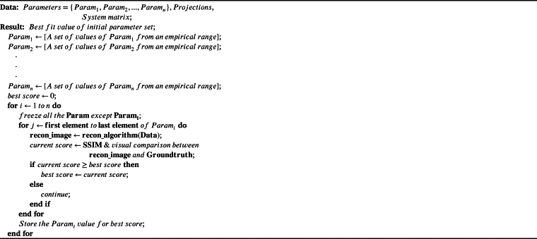
For both the OS-SART and ASD-POCS algorithms there are initial hyperparameters described in [40], [41] which must need to be optimized for a specific device geometry and trajectory for the convergence to the solution. For this study, a semi-automated trial and error-based brute-force approach was applied for the parameter optimization. All the parameters were taken as a variable one by one in a feasible range and were fixed at the best reconstruction performance. Initially, the parameters were optimized for the proposed trajectory which was developed with 600 projections. Furthermore, the trajectory and reconstruction algorithm parameters were optimized again for a reduced 380 projection setup to make it comparable with the conventional limited-angle circular trajectory setup.
A typical algorithm for the parameter optimization is shown in Algorithm 1. The optimization time is dependent on the empirical values chosen and the computing device.
Algorithm 1.
The brute-force approach to optimize the initial parameter set for iterative reconstruction algorithms.
2.6. Experiments
This study has three sets of experiments considering the trajectories and the two iterative reconstruction algorithms for both the imaging phantoms, Jerry and Tom. Poisson noise and Gaussian noise have been added to the simulated projection data in every experiment to mimic the CT noise.
2.6.1. Experiment-1: reconstruction with standard trajectory using OS-SART
The first experiment is the reconstruction of the volume using the Digitally Rendered Radiograph (DRR) data computed in computer simulation from the standard limited angle circular scan of the device using the OS-SART reconstruction algorithm which is similar to the real-life scan setup of 390 projections.
2.6.2. Experiment-2: reconstruction with proposed fusion trajectory using OS-SART and ASD-POCS
The second experiment consists of simulating the DRRs with the proposed fusion trajectory, and then to reconstruct the volume with OS-SART and ASD-POCS algorithms for both Jerry and Tom Phantoms. The experimental device can take a maximum of 720 projections for a full circular scan. Therefore, for this experiment, a total of 600 numbers of projections were taken from the proposed trajectory containing 375 projections from the shifted iso-center elliptical trajectory part and 225 projections from the VOI-guided part (as data augmentation) for maximum FOV volume reconstruction with the best possible image quality.
2.6.3. Experiment-3: reconstruction with proposed fusion trajectory using OS-SART and ASD-POCS in less projections set up
For the third part of the experiment, the second part was repeated with the same proposed fusion trajectory, however, with less number of projections. For this experiment, a total of 387 projections were taken containing 272 numbers of elliptical trajectory projections and 115 numbers of VOI-guided projections (as data augmentation) from the proposed fusion trajectory. This experiment is the refined version of experiment-2.6.2 with fewer projections to compare the result with the current limited circular trajectory scanning which uses 390 numbers of projections to reconstruct the volume.
2.7. Image quality assessment metrics
To perform the quantitative analysis of this study, The Peak Signal to Noise Ratio (PSNR) and Structural Similarity Index Measurements (SSIM) metrics were used for a heterogeneous image reconstruction quality analysis. Moreover, to cross-check the performance of PSNR and SSIM metrics, Root Mean Squared Error (RMSE) and the Universal Quality Index (UQI) scores were also calculated. The detailed mathematical explanation of these metrics has been explained in Section Appendix B, Appendix C, Appendix D, and Appendix E in the supplementary materials.
In all the experiments (2.6.1, 2.6.2, 2.6.3), these image quality measurement metrics have been applied in the prominent slices (mostly the middle slices where the organ is maximally visible) containing the VOIs and specifically at the VOIs to evaluate the quantitative accuracy of the reconstructed images. Furthermore, these metrics were applied to the 3D volume of the VOIs, and the whole reconstructed volume containing the VOIs.
3. Results
The optimized parameter set for both the OS-SART and ASD-POCS algorithm is listed in Table 1. The parameter labels are taken from TIGRE toolbox [38]. The toolbox is open source and available on GitHub.
Table 1.
The optimized set of parameters of OS-SART and ASD-POCS algorithm for the proposed fusion trajectory.
| OS-SART |
ASD-POCS |
||
|---|---|---|---|
| Parameter | Optimized Value | Parameter | Optimized Value |
| niter | 20 | niter | 20 |
| lambda | 1 | lambda | 1 |
| lambda_red | 0.999 | lambda_red | 0.9999 |
| BlockSize | 17 | TViter | 15 |
| OrderStrategy | ‘angular distance’ | maxL2err | 90% |
| alpha | 0.003 | ||
| Ratio | 0.94 | ||
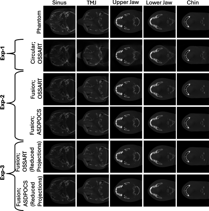
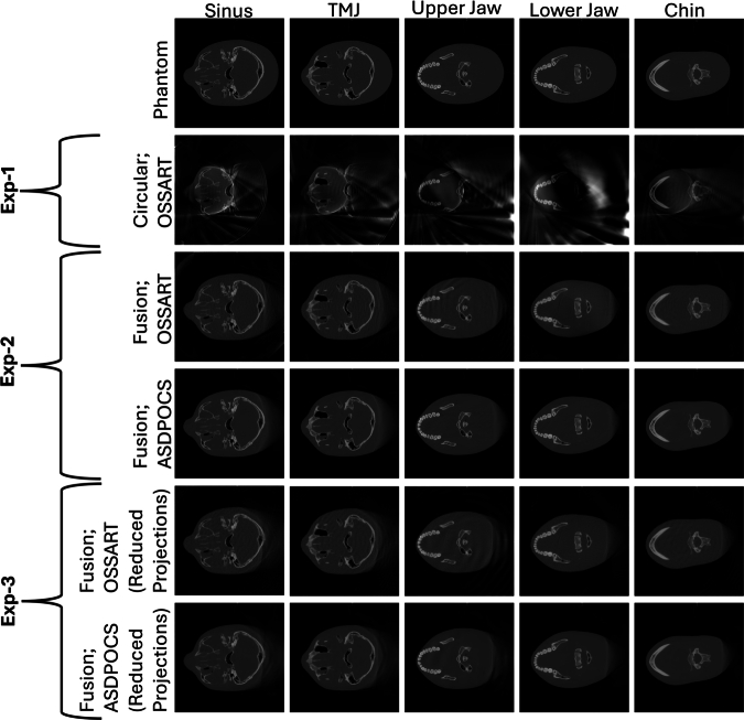
Fig. 7, Fig. 8 exhibit the results for all three experiments performed in this study for the phantom Jerry and Tom respectively in different VOIs: sinus, TMJ, upper jaw, lower jaw, and chin. For the conventional limited angle circular scan, the FOV size is a circle of diameter. However, the FOVs obtained from our proposed trajectory do not have any uniform or regular shape, although it was undoubtedly extended compared to the FOV obtained from the regular trajectory which is cylindrical in 3D space. Therefore, the FOV for the proposed trajectory was measured in the previously mentioned five VOI slices in both cranial breadth and naso-occipital length direction, and with our proposed trajectory the maximum FOV achieved in the cranial breadth and naso-occipital length is and respectively. Highlighting the significant FOV extension in both directions using our proposed novel trajectory.
Fig. 7.
All the reconstructed images for the Jerry phantom from experiment 1, 2, 3. Five different columns exhibit five different VOIs. First row: The digital phantom; Second row: The results from experiment 1; Third and Fourth row: The results from experiment 2; And, the Fifth and Sixth row: The results from experiment 3.
Fig. 8.
All the reconstructed images for the Tom phantom from experiment 1, 2, 3. Five different columns exhibit five different VOIs. First row: The digital phantom; Second row: The results from experiment 1; Third and Fourth row: The results from experiment 2; And, the Fifth and Sixth row: The results from experiment 3.
Table 2, Table 4 report the detailed quantitative quality measurement score for all the metrics mentioned in Section-2.7 for each of the five VOIs for both Jerry and Tom respectively. The middle or most prominent slices of the particular VOIs have been chosen to evaluate the extended FOV size for the lateral extended FOV. Section Appendix G in the supplementary material exhibits the detailed FOV measurement for all the VOIs.
Table 2.
Jerry: Quality measurement scores in different VOIs for different trajectories and corresponding reconstruction algorithms. Measurement is taken at the most prominent slices of the respected VOI along the z-axis. In VOI: measurement only inside each VOI region; Whole Slice: measurement in the whole slice related to each VOI.
| Trajectory | VOI | PSNR |
SSIM |
||
|---|---|---|---|---|---|
| In VOI | Whole slice | in VOI | Whole slice | ||
| Sinus | 28.5935 | 21.1281 | 0.9792 | 0.7520 | |
| Circular; | TMJ | 37.4164 | 22.1337 | 0.9935 | 0.7789 |
| OSSART | Upper Jaw | 25.7520 | 22.7246 | 0.9542 | 0.8170 |
| Lower Jaw | 27.4749 | 25.0951 | 0.9672 | 0.8597 | |
| Chin | 31.1546 | 27.0987 | 0.9834 | 0.9080 | |
| Sinus | 36.1103 | 30.7057 | 0.9837 | 0.8686 | |
| Fusion; | TMJ | 43.2929 | 31.1151 | 0.9948 | 0.8672 |
| OSSART | Upper Jaw | 32.6921 | 30.8363 | 0.9598 | 0.8996 |
| Lower Jaw | 33.4874 | 31.3960 | 0.9691 | 0.9084 | |
| Chin | 35.1400 | 32.1087 | 0.9816 | 0.9148 | |
| Sinus | 46.6413 | 40.1683 | 0.9962 | 0.9665 | |
| Fusion; | TMJ | 53.8594 | 41.5986 | 0.9991 | 0.9688 |
| ASDPOCS | Upper Jaw | 45.0462 | 42.8082 | 0.9946 | 0.9832 |
| Lower Jaw | 45.7294 | 43.3618 | 0.9962 | 0.9860 | |
| Chin | 49.0815 | 45.7565 | 0.9986 | 0.9912 | |
| Fusion; | Sinus | 35.1702 | 30.3879 | 0.9829 | 0.8696 |
| OSSART; | TMJ | 43.2229 | 30.9937 | 0.9950 | 0.8743 |
| Reduced | Upper Jaw | 32.1469 | 30.4541 | 0.9609 | 0.9027 |
| projections | Lower Jaw | 33.0697 | 31.1404 | 0.9704 | 0.9140 |
| Chin | 34.3213 | 31.6757 | 0.9831 | 0.9245 | |
| Fusion; | Sinus | 41.1827 | 35.3547 | 0.9941 | 0.9499 |
| ASDPOCS; | TMJ | 49.0731 | 36.6566 | 0.9987 | 0.9573 |
| Reduced | Upper Jaw | 38.9620 | 36.9718 | 0.9923 | 0.9716 |
| projections | Lower Jaw | 39.5378 | 37.5330 | 0.9945 | 0.9765 |
| Chin | 41.5771 | 38.5493 | 0.9977 | 0.9856 | |
Table 4.
Tom: Quality measurement scores in different VOIs for different trajectories and corresponding reconstruction algorithms. Measurement is taken at the most prominent slices of the respected VOI along the z-axis. In VOI: measurement only inside each VOI region; Whole Slice: measurement in the whole slice related to each VOI.
| Trajectory | VOI | PSNR |
SSIM |
||
|---|---|---|---|---|---|
| (in VOI) | (Whole slice) | (in VOI) | (Whole slice) | ||
| Sinus | 24.8817 | 15.5644 | 0.9567 | 0.6810 | |
| Circular; | TMJ | 31.8350 | 15.7035 | 0.9892 | 0.6824 |
| OSSART | Upper Jaw | 20.8897 | 15.8851 | 0.9354 | 0.7131 |
| Lower Jaw | 21.4372 | 16.3203 | 0.9432 | 0.7202 | |
| Chin | 23.4239 | 17.2051 | 0.9630 | 0.7802 | |
| Sinus | 38.7543 | 29.7584 | 0.9912 | 0.9164 | |
| Fusion; | TMJ | 45.7258 | 30.3802 | 0.9985 | 0.9158 |
| OSSART | Upper Jaw | 34.9699 | 31.0197 | 0.9876 | 0.9233 |
| Lower Jaw | 35.5231 | 31.7132 | 0.9908 | 0.9303 | |
| Chin | 39.3963 | 33.9972 | 0.9960 | 0.9568 | |
| Sinus | 47.8494 | 35.2701 | 0.9976 | 0.9599 | |
| Fusion; | TMJ | 53.1047 | 34.8657 | 0.9997 | 0.9592 |
| ASDPOCS | Upper Jaw | 45.2907 | 37.6667 | 0.9977 | 0.9641 |
| Lower Jaw | 45.8654 | 39.1038 | 0.9989 | 0.9703 | |
| Chin | 48.4115 | 40.2593 | 0.9993 | 0.9770 | |
| Fusion; | Sinus | 40.3104 | 31.2519 | 0.9909 | 0.9085 |
| OSSART; | TMJ | 47.1235 | 30.7181 | 0.9984 | 0.9047 |
| Reduced | Upper Jaw | 36.5774 | 31.3960 | 0.9885 | 0.9083 |
| projections | Lower Jaw | 37.1682 | 33.0961 | 0.9909 | 0.9284 |
| Chin | 42.7239 | 36.6161 | 0.9963 | 0.9524 | |
| Fusion; | Sinus | 40.2724 | 31.3741 | 0.9919 | 0.9195 |
| ASDPOCS; | TMJ | 46.5171 | 31.1403 | 0.9980 | 0.9240 |
| Reduced | Upper Jaw | 37.3895 | 31.7105 | 0.9908 | 0.9313 |
| projections | Lower Jaw | 38.1525 | 33.8002 | 0.9924 | 0.9488 |
| Chin | 42.7103 | 36.5687 | 0.9966 | 0.9621 | |
Table 3, Table 5 show the quantitative measurement scores of the reconstructed volume (3D). The measurement was taken both in only combined indicated VOI region i.e., all combined five VOIs (In VOI) and in the whole reconstructed region (Whole Volume).
Table 3.
Jerry: Quality measurement scores measured in the whole reconstructed volume for different trajectories and corresponding reconstruction algorithms. In VOI: measurement in the total VOI region (related to all five VOIs); Whole Volume: measurement in the whole reconstructed volume containing the VOI.
| Trajectory | PSNR |
SSIM |
||
|---|---|---|---|---|
| (in VOI) | (Whole Volume) | (in VOI) | (Whole Volume) | |
| Circular;OSSART | 31.8048 | 25.9080 | 0.9880 | 0.9373 |
| Fusion;OSSART | 38.2879 | 33.3871 | 0.9896 | 0.9444 |
| Fusion;ASDPOCS | 50.3861 | 45.0632 | 0.9986 | 0.9917 |
| Fusion;OSSART; Reduced projections | 37.7906 | 33.1499 | 0.9899 | 0.9491 |
| Fusion;ASDPOCS; Reduced projections | 44.2543 | 38.6958 | 0.9979 | 0.9885 |
Table 5.
Tom: Quality measurement scores measured in the whole reconstructed volume for different trajectories and corresponding reconstruction algorithms. In VOI: measurement in the total VOI region (related to all five VOIs); Whole Volume: measurement in the whole reconstructed volume containing the VOI.
| Trajectory | PSNR |
SSIM |
||
|---|---|---|---|---|
| (in VOI) | (Whole Volume) | (in VOI) | (Whole Volume) | |
| Circular;OSSART | 27.8173 | 21.3781 | 0.9826 | 0.9075 |
| Fusion;OSSART | 42.4092 | 36.7414 | 0.9978 | 0.9805 |
| Fusion;ASDPOCS | 51.9708 | 42.8008 | 0.9996 | 0.9910 |
| Fusion;OSSART; Reduced projections | 44.2972 | 37.5982 | 0.9980 | 0.9777 |
| Fusion;ASDPOCS; Reduced projections | 44.6559 | 37.6372 | 0.9981 | 0.9819 |
Image quality metrics were always calculated in both inside the VOI region (In VOI) and the entire region (Whole Slice). In all experiments, higher performance was observed in the quantitative image quality metrics for the fusion trajectory compared to the circular trajectory, emphasizing the improved image quality by our proposed trajectory.
For the reduced projection version of the proposed trajectory, the quality measurement metric scores decrease slightly, however, still outperforms the limited angle circular trajectory in both metric scores and FOV size.
4. Discussion and conclusion
In this study, a novel source-detector trajectory was developed targeting the FOV extension preserving the acceptable image quality in certain VOIs. The proposed trajectory uses the concept of maximum projection data acquisition from Tuy's condition and an off-axis scanning method. The proposed trajectory exhibited excellent results in FOV expansion with adequate image reconstruction quality.
The proposed fusion trajectory was designed based on the device geometry and the extended headspace discussed in Sections 2.1 and 2.3. Consequently, this trajectory can be applied to any head phantom that fits within the extended headspace. Fig. 7 shows that, for the small phantom-Jerry, the upper jaw, lower jaw, and chin are well-reconstructed, however, sinus and TMJ bones were partially reconstructed at the FOV boundary for the limited angle circular trajectory. With the proposed trajectory, All the VOIs; sinus, TMJ, upper jaw, lower jaw, and chin are well-reconstructed. Moreover, the whole Jerry phantom volume is nearly well-reconstructed in the VOI-containing regions. On the other hand, for the ideal-sized phantom-Tom, Fig. 8 shows that only the upper jaw, lower jaw, and chin are well-reconstructed, the sinus is partially reconstructed at the FOV boundary, and TMJ bones are completely out of the reconstructed FOV boundary for the limited angle circular scan. However, with the proposed trajectory all the VOIs (sinus, TMJ, upper jaw, lower jaw, and chin) are well-reconstructed, and the FOV almost has reconstructed nearly 90% of the target volume of the VOI-containing region. Moreover, the refined fewer projection setup of the proposed trajectory also can reconstruct the extended volume. The detailed FOV measurement is provided in Section Appendix G in the supplementary materials.
The quality measurement scores from Table 2, Table 3, Table 4, Table 5 show that all the quality measurement scores are higher for the proposed trajectory. Although for the refined less projection setup of the trajectory, the scores drop a little bit, however, still it outperforms the limited circular scan reconstruction result. In addition, the quantitative results prove that the ASD-POCS algorithm outperforms OS-SART in all experiments. The detailed score and their inter-trajectory relations are explained in Figure H.2 and Figure H.3 provided in the supplementary materials.
The primary goals of this study were fulfilled, as the proposed trajectory can reconstruct an extended FOV than the standard limited angle circular scan trajectory. Although for the proposed trajectory, the gantry needs to rotate twice, no complex hardware modification is needed. Moreover, excellent image quality performance was observed with the trajectory for a reduced projection number compared to the standard circular trajectory which reduces the necessity of a high projection number, thus reducing the radiation dose. Our study is the first demonstration of the lateral FOV extension in dental CBCT imaging. In the aforementioned non-stationary off-axis iso-centric elliptical trajectory [34], the FOV was extended with certain source-detector movement constraints. Our proposed trajectory compensates for the existing movement constraints and achieves a larger FOV than the standard circular scan. Considering that our device is the small dental CBCT unit and comparing the device size used in this study [34], the achieved FOV based on our method is more significant. Moreover, a complimentary circular scan approach [35] requires two different circular scans which increase the radiation dosage. Although our trajectory requires two rotations, it needs the same number of projections as the standard circular scan which achieves a larger FOV without increasing the radiation dosage. In the rotating detector [36] and dynamic detector offset approach [20], complex mechanical modification and tuning are required during the scanning. However, our proposed trajectory exhibits better projection acquisition without any complex mechanical modification during the scan and using the same radiation dose as the standard circular trajectory. In addition, our proposed trajectory exhibits a better image quality measurement score than the standard circular trajectory. A comprehensive comparison of image quality metrics for the reconstructed images, derived from all the used trajectories and reconstruction algorithms, is provided in Section Appendix H of the supplementary materials.
We acknowledge that the scanning time for the proposed trajectory may be higher than the regular trajectory scanning time. This scanning time is device-dependent and varies considering the build-equipment of the device. This extended scanning may also lead to motion artifacts in case the patient moves during the scanning process. To minimize the patient's movement the device has a biting mechanism where the patient will bite during the scanning. Therefore, it should reduce the artifact mechanically. Moreover, post-scanning algorithmic processes such as motion compensation and image registration-based approaches may be required for further motion artifact reduction. We also acknowledge some limitations of this study. The experiments were done based on simulations and a verification of all experiments using real-world data is required which is a future perspective of this study. In addition, for the mechanical implementation, minor upgradation may need based on the machine's geometry and its specific mechanical movement possibilities.
In summary, the trajectory proposed in our technical study shows strong potential for significantly expanding the field of view (FOV) and enhancing image quality, as indicated by improved metric scores. Additionally, both the FOV and image quality metrics suggest that this approach could reduce radiation exposure compared to the standard circular trajectory of smaller dental CBCT devices. Although not yet tested in clinical cases, the strong mathematical background of the study supports that the proposed fusion trajectory may ultimately reduce the need for larger CBCT devices for numerous clinical applications, offering a more cost-effective solution that supports precise diagnosis and tailored treatment plans for patients in future.
CRediT authorship contribution statement
S M Ragib Shahriar Islam: Writing – review & editing, Writing – original draft, Visualization, Validation, Methodology, Investigation, Formal analysis, Data curation, Conceptualization. Ander Biguri: Writing – review & editing, Validation, Supervision, Software, Methodology, Investigation, Formal analysis, Conceptualization. Claudio Landi: Resources, Project administration, Funding acquisition, Conceptualization. Giovanni Di Domenico: Writing – review & editing, Validation, Supervision, Methodology, Investigation, Formal analysis, Conceptualization. Benedikt Schneider: Validation, Supervision, Investigation. Pascal Grün: Validation, Supervision. Cristina Sarti: Resources, Investigation, Conceptualization. Ramona Woitek: Supervision, Conceptualization. Andrea Delmiglio: Validation, Conceptualization. Carola-Bibiane Schönlieb: Writing – review & editing, Validation. Dritan Turhani: Validation. Gernot Kronreif: Supervision, Resources, Project administration, Funding acquisition. Wolfgang Birkfellner: Writing – review & editing, Supervision, Conceptualization. Sepideh Hatamikia: Writing – review & editing, Writing – original draft, Supervision, Project administration, Methodology, Investigation, Funding acquisition, Formal analysis, Conceptualization.
Declaration of Competing Interest
The authors have declared no conflict of interest.
Acknowledgements
This study was supported by NÖ FTI Grundlagenforschung project (Project number: GLF21-1-001). In addition, this work has been supported by ACMIT—Austrian Center for Medical Innovation and Technology, which is funded within the scope of the COMET program and funded by Austrian BMVIT and BMWFW and the governments of Lower Austria and Tyrol. We would like to thank Dr. Geevarghese George for his support and guidance. The authors have confirmed that any identifiable participants in this study have given their consent for publication.
Footnotes
Supplementary material related to this article can be found online at https://doi.org/10.1016/j.csbj.2024.11.010.
Appendix. Supplementary material
The following is the Supplementary material related to this article.
This supplementary material offers a comprehensive overview of the search space, highlighting the valid and invalid regions of the trajectory based on the geometry of the experimental device. It provides an in-depth explanation of the image quality metrics used, including Peak Signal-to-Noise Ratio (PSNR), Structural Similarity Index Measure (SSIM), Universal Quality Index (UQI), and Root Mean Squared Error (RMSE). Additionally, it presents extended quantitative evaluations of the reconstructed images, detailed field-of-view (FOV) measurements, and a performance comparison of all tested trajectories and image reconstruction algorithms.
References
- 1.Pelc N.J., Chesler D.A. Utilization of cross-plane rays for three-dimensional reconstruction by filtered back-projection. J Comput Assist Tomogr. 1979;3(3):385–395. doi: 10.1097/00004728-197906000-00015. [DOI] [PubMed] [Google Scholar]
- 2.Tuy H.K. An inversion formula for cone-beam reconstruction. SIAM J Appl Math. 1983;43(3):546–552. [Google Scholar]
- 3.Mozzo P., Procacci C., Tacconi A., Tinazzi Martini P., Bergamo Andreis I. A new volumetric CT machine for dental imaging based on the cone-beam technique: preliminary results. Eur Radiol. 1998;8:1558–1564. doi: 10.1007/s003300050586. [DOI] [PubMed] [Google Scholar]
- 4.Arai Y., Tammisalo E., Iwai K., Hashimoto K., Shinoda K. Development of a compact computed tomographic apparatus for dental use. Dentomaxillofacial Radiol. 1999;28(4):245–248. doi: 10.1038/sj/dmfr/4600448. [DOI] [PubMed] [Google Scholar]
- 5.Patel S., Brown J., Semper M., Abella F., Mannocci F. European society of endodontology position statement: use of cone beam computed tomography in endodontics: European society of endodontology (ESE) developed by. Int Endod J. 2019;52(12):1675–1678. doi: 10.1111/iej.13187. [DOI] [PubMed] [Google Scholar]
- 6.Naitoh M., Nakahara K., Suenaga Y., Gotoh K., Kondo S., Ariji E. Comparison between cone-beam and multislice computed tomography depicting mandibular neurovascular canal structures. Oral Surg Oral Med Oral Pathol Oral Radiol Endo. 2010;109(1):e25–e31. doi: 10.1016/j.tripleo.2009.08.027. [DOI] [PubMed] [Google Scholar]
- 7.Ma B., Park T., Chun I., Yun K. The accuracy of a 3D printing surgical guide determined by CBCT and model analysis. J Adv Prosthodont. 2018;10(4):279–285. doi: 10.4047/jap.2018.10.4.279. [DOI] [PMC free article] [PubMed] [Google Scholar]
- 8.Harris D., Horner K., Gröndahl K., Jacobs R., Helmrot E., Benic G.I., et al. EAO guidelines for the use of diagnostic imaging in implant dentistry 2011. A consensus workshop organized by the European association for osseointegration at the medical university of Warsaw. Clin Oral Implants Res. 2012;23(11):1243–1253. doi: 10.1111/j.1600-0501.2012.02441.x. [DOI] [PubMed] [Google Scholar]
- 9.Popat H., Richmond S. New developments in: three-dimensional planning for orthognathic surgery. J Orthod. 2010;37(1):62–71. doi: 10.1179/14653121042885. [DOI] [PubMed] [Google Scholar]
- 10.BOS B.O.S. Guidelines for the use of radiographs in clinical orthodontics. 2015. www.bos.org.uk Available from:
- 11.Salineiro F.C.S., Kobayashi-Velasco S., Braga M.M., Cavalcanti M.G.P. Radiographic diagnosis of root fractures: a systematic review, meta-analyses and sources of heterogeneity. Dentomaxillofacial Radiol. 2017;46(8) doi: 10.1259/dmfr.20170400. [DOI] [PMC free article] [PubMed] [Google Scholar]
- 12.Fakhran S., Alhilali L., Sreedher G., Dohatcu A.C., Lee S., Ferguson B., et al. Comparison of simulated cone beam computed tomography to conventional helical computed tomography for imaging of rhinosinusitis. Laryngoscope. 2014;124(9):2002–2006. doi: 10.1002/lary.24603. [DOI] [PubMed] [Google Scholar]
- 13.Zojaji R., Naghibzadeh M., Mazloum Farsi Baf M., Nekooei S., Bataghva B., Noorbakhsh S. Diagnostic accuracy of cone-beam computed tomography in the evaluation of chronic rhinosinusitis. ORL. 2015;77(1):55–60. doi: 10.1159/000373927. [DOI] [PubMed] [Google Scholar]
- 14.De Boer E., Dijkstra P., Stegenga B., De Bont L., Spijkervet F. Value of cone-beam computed tomography in the process of diagnosis and management of disorders of the temporomandibular joint. Br J Oral Maxillofac Surg. 2014;52(3):241–246. doi: 10.1016/j.bjoms.2013.12.007. [DOI] [PubMed] [Google Scholar]
- 15.Venskutonis T., Plotino G., Juodzbalys G., Mickevičienė L. The importance of cone-beam computed tomography in the management of endodontic problems: a review of the literature. J Endod. 2014;40(12):1895–1901. doi: 10.1016/j.joen.2014.05.009. [DOI] [PubMed] [Google Scholar]
- 16.Kau C.H., Božič M., English J., Lee R., Bussa H., Ellis R.K. Cone-beam computed tomography of the maxillofacial region—an update. Int J Med Robot Comput Assist Surg. 2009;5(4):366–380. doi: 10.1002/rcs.279. [DOI] [PubMed] [Google Scholar]
- 17.Patel S. New dimensions in endodontic imaging: part 2. Cone beam computed tomography. Int Endod J. 2009;42(6):463–475. doi: 10.1111/j.1365-2591.2008.01531.x. [DOI] [PubMed] [Google Scholar]
- 18.Lee J., Stayman J.W., Otake Y., Schafer S., Zbijewski W., Khanna A.J., et al. Volume-of-change cone-beam CT for image-guided surgery. Phys Med Biol. 2012;57(15):4969. doi: 10.1088/0031-9155/57/15/4969. [DOI] [PMC free article] [PubMed] [Google Scholar]
- 19.Fotouhi J., Fuerst B., Unberath M., Reichenstein S., Lee S.C., Johnson A.A., et al. Automatic intraoperative stitching of nonoverlapping cone-beam CT acquisitions. Med Phys. 2018;45(6):2463–2475. doi: 10.1002/mp.12877. [DOI] [PMC free article] [PubMed] [Google Scholar]
- 20.Herbst M., Schebesch F., Berger M., Choi J.-H., Fahrig R., Hornegger J., et al. Dynamic detector offsets for field of view extension in c-arm computed tomography with application to weight-bearing imaging. Med Phys. 2015;42(5):2718–2729. doi: 10.1118/1.4915542. [DOI] [PMC free article] [PubMed] [Google Scholar]
- 21.Hatamikia S., Biguri A., Herl G., Kronreif G., Reynolds T., Kettenbach J., et al. Source-detector trajectory optimization in cone-beam computed tomography: a comprehensive review on today's state-of-the-art. Phys Med Biol. 2022;67(16) doi: 10.1088/1361-6560/ac8590. [DOI] [PubMed] [Google Scholar]
- 22.Zeng G.L., Gullberg G. A cone-beam tomography algorithm for orthogonal circle-and-line orbit. Phys Med Biol. 1992;37(3):563. doi: 10.1088/0031-9155/37/3/005. [DOI] [PubMed] [Google Scholar]
- 23.Yu Z., Wunderlich A., Dennerlein F., Lauritsch G., Noo F. Line plus arc source trajectories and their R-line coverage for long-object cone-beam imaging with a C-arm system. Phys Med Biol. 2011;56(12):3447–3471. doi: 10.1088/0031-9155/56/12/001. [DOI] [PMC free article] [PubMed] [Google Scholar]
- 24.Köhler T., Proksa R., Grass M. A fast and efficient method for sequential cone-beam tomography. Med Phys. 2001;28(11):2318–2327. doi: 10.1118/1.1395025. [DOI] [PubMed] [Google Scholar]
- 25.Zheng D., Lu J., Jefferson A., Zhang C., Wu J., Sleeman W., et al. A protocol to extend the longitudinal coverage of on-board cone-beam CT. J Appl Clin Med Phys. 2012;13(4):141–151. doi: 10.1120/jacmp.v13i4.3796. [DOI] [PMC free article] [PubMed] [Google Scholar]
- 26.Yu Z., Lauritsch G., Dennerlein F., Mao Y., Hornegger J., Noo F. Extended ellipse-line-ellipse trajectory for long-object cone-beam imaging with a mounted C-arm system. Phys Med Biol. 2016;61(4):1829. doi: 10.1088/0031-9155/61/4/1829. [DOI] [PubMed] [Google Scholar]
- 27.Guo Z., Lauritsch G., Maier A., Kugler P., Islam M., Vogt F., et al. C-arm CT imaging with the extended line-ellipse-line trajectory: first implementation on a state-of-the-art robotic angiography system. Phys Med Biol. 2020;65(18) doi: 10.1088/1361-6560/ab9a82. [DOI] [PubMed] [Google Scholar]
- 28.Rafic K.M., Peace S.B.T., Manu M., Arvind S., Ravindran B.P. A rationale for cone beam CT with extended longitudinal field-of-view in image guided adaptive radiotherapy. Phys Med. 2019;62:129–139. doi: 10.1016/j.ejmp.2019.03.007. [DOI] [PubMed] [Google Scholar]
- 29.Tan J., Li H.H., Klein E., Li H., Parikh P., Yang D. Physical phantom studies of helical cone-beam CT with exact reconstruction. Med Phys. 2012;39(8):4695–4704. doi: 10.1118/1.4736535. [DOI] [PubMed] [Google Scholar]
- 30.Yu Z., Noo F., Dennerlein F., Lauritsch G., Hornegger J. 2011 IEEE nuclear science symposium conference record. IEEE; 2011. FDK-type reconstruction algorithms for the reverse helical trajectory; pp. 3980–3985. [Google Scholar]
- 31.Yu Z., Maier A., Lauritsch G., Vogt F., Schönborn M., Köhler C., et al. 2014 IEEE nuclear science symposium and medical imaging conference (NSS/MIC) IEEE; 2014. Image quality assessment for extended-volume C-arm CT using a multi-turn reverse helix; pp. 1–4. [Google Scholar]
- 32.Reynolds T., Ma Y.Q., Kanawati A.J., Constantinidis A., Williams Z., Gang G., et al. Extended intraoperative longitudinal 3-dimensional cone beam computed tomography imaging with a continuous multi-turn reverse helical scan. Invest Radiol. 2022;57(11):764–772. doi: 10.1097/RLI.0000000000000885. [DOI] [PMC free article] [PubMed] [Google Scholar]
- 33.Gang G.J., Zbijewski W., Mahesh M., Thawait G., Packard N., Yorkston J., et al. Image quality and dose for a multisource cone-beam CT extremity scanner. Med Phys. 2018;45(1):144–155. doi: 10.1002/mp.12659. [DOI] [PubMed] [Google Scholar]
- 34.Li T., Li X., Yang Y., Heron D.E., Huq M.S. A novel off-axis scanning method for an enlarged ellipse cone-beam computed tomography field of view. Med Phys. 2010;37(12):6233–6239. doi: 10.1118/1.3514130. [DOI] [PubMed] [Google Scholar]
- 35.Yang D., Li H.H., Goddu S.M., Tan J. CBCT volumetric coverage extension using a pair of complementary circular scans with complementary kV detector lateral and longitudinal offsets. Phys Med Biol. 2014;59(21):6327. doi: 10.1088/0031-9155/59/21/6327. [DOI] [PubMed] [Google Scholar]
- 36.Stromer D., Kugler P., Bauer S., Lauritsch G., Maier A. Bildverarbeitung für die Medizin 2016: Algorithmen–Systeme–Anwendungen. Springer; 2016. Data completeness estimation for 3d c-arm scans with rotated detector to enlarge the lateral field-of-view; pp. 164–169. [Google Scholar]
- 37.Feldkamp L.A., Davis L.C., Kress J.W. Practical cone-beam algorithm. J Opt Soc Amer A. 1984;1(6):612–619. [Google Scholar]
- 38.Biguri A., Dosanjh M., Hancock S., Soleimani M. TIGRE: a MATLAB-GPU toolbox for CBCT image reconstruction. Biomed Phys Eng Express. 2016;2(5) [Google Scholar]
- 39.Andersen A.H., Kak A.C. Simultaneous algebraic reconstruction technique (SART): a superior implementation of the ART algorithm. Ultrason Imag. 1984;6(1):81–94. doi: 10.1177/016173468400600107. [DOI] [PubMed] [Google Scholar]
- 40.Wang G., Jiang M. Ordered-subset simultaneous algebraic reconstruction techniques (OS-SART) J X-Ray Sci Technol. 2004;12(3):169–177. [Google Scholar]
- 41.Sidky E.Y., Pan X. Image reconstruction in circular cone-beam computed tomography by constrained, total-variation minimization. Phys Med Biol. 2008;53(17):4777. doi: 10.1088/0031-9155/53/17/021. [DOI] [PMC free article] [PubMed] [Google Scholar]
Associated Data
This section collects any data citations, data availability statements, or supplementary materials included in this article.
Supplementary Materials
This supplementary material offers a comprehensive overview of the search space, highlighting the valid and invalid regions of the trajectory based on the geometry of the experimental device. It provides an in-depth explanation of the image quality metrics used, including Peak Signal-to-Noise Ratio (PSNR), Structural Similarity Index Measure (SSIM), Universal Quality Index (UQI), and Root Mean Squared Error (RMSE). Additionally, it presents extended quantitative evaluations of the reconstructed images, detailed field-of-view (FOV) measurements, and a performance comparison of all tested trajectories and image reconstruction algorithms.


